EP0290734A2 - Magnet switch for a starter - Google Patents
Magnet switch for a starter Download PDFInfo
- Publication number
- EP0290734A2 EP0290734A2 EP88103542A EP88103542A EP0290734A2 EP 0290734 A2 EP0290734 A2 EP 0290734A2 EP 88103542 A EP88103542 A EP 88103542A EP 88103542 A EP88103542 A EP 88103542A EP 0290734 A2 EP0290734 A2 EP 0290734A2
- Authority
- EP
- European Patent Office
- Prior art keywords
- switch
- chamber
- plunger
- bobbin
- coil
- Prior art date
- Legal status (The legal status is an assumption and is not a legal conclusion. Google has not performed a legal analysis and makes no representation as to the accuracy of the status listed.)
- Granted
Links
Images


Classifications
-
- H—ELECTRICITY
- H01—ELECTRIC ELEMENTS
- H01H—ELECTRIC SWITCHES; RELAYS; SELECTORS; EMERGENCY PROTECTIVE DEVICES
- H01H51/00—Electromagnetic relays
- H01H51/02—Non-polarised relays
- H01H51/04—Non-polarised relays with single armature; with single set of ganged armatures
- H01H51/06—Armature is movable between two limit positions of rest and is moved in one direction due to energisation of an electromagnet and after the electromagnet is de-energised is returned by energy stored during the movement in the first direction, e.g. by using a spring, by using a permanent magnet, by gravity
- H01H51/065—Relays having a pair of normally open contacts rigidly fixed to a magnetic core movable along the axis of a solenoid, e.g. relays for starting automobiles
-
- H—ELECTRICITY
- H01—ELECTRIC ELEMENTS
- H01H—ELECTRIC SWITCHES; RELAYS; SELECTORS; EMERGENCY PROTECTIVE DEVICES
- H01H9/00—Details of switching devices, not covered by groups H01H1/00 - H01H7/00
- H01H9/02—Bases, casings, or covers
- H01H9/04—Dustproof, splashproof, drip-proof, waterproof, or flameproof casings
- H01H9/047—Dustproof, splashproof, drip-proof, waterproof, or flameproof casings provided with venting means
Definitions
- the present invention relates in general to switches used to activate a starting motor of a vehicle.
- Known starter magnet switches are structurally arranged in such a manner that moisture and dust laden air flows from outside of the switch all the way into the innermost cavities thereof which contain the switch contacts. There, dust and water tend to accumulate on the fixed and movable contacts and degrade the performance of the switch. In cold weather, the water on the contacts freezes to ice which can completely prevent electrical contact from being made.
- a hole is formed in a plunger boot of the switch so that a plunger chamber within a coil communicates with the inside of a starter housing through a gap between an inner surface of the coil and an outer surface of the plunger. Accordingly, air compressed within the plunger chamber as a result of movement of a plunger flows into the inside of the starter housing through the gap and the hole of the plunger boot.
- the distance between the inside of the starter housing and the plunger chamber is short, and especially the length of the hole of the plunger boot is very short. Accordingly, upon the plunger's return stroke, water that has entered the starter housing may enter the plunger chamber through the short gap.
- the contact chamber communicates with the plunger chamber, the volume of the plunger boot and the plunger chamber becomes small when the plunger returns. Water having entered the plunger chamber moves easily into the contact chamber. Similarly, dust can easily enter into the conduct chamber. Water in the contact chamber freezes in cold weather thereby preventing electrical connection between contacts and dust accumulating in the chamber tends to deteriorate performance.
- the switch is structured so that the passage between the contact chamber and the outside is elongated with respect to prior art devices by making use of a long passage between the inner circumference of a bobbin and a sleeve.
- the outside communicates with the long passage through a coil chamber.
- This long passage presents a high flow resistance to the air, air carrying dust and water droplets are substantially prevented from entering the chamber through the long passage.
- the invention provides a magnet switch arrangement having a long flow path through which outside air must pass to enter the inner chamber of the switch where its working contacts are located to prevent the accumulation of dust and moisture therein.
- a coil unit (3) having a bobbin (4) is provided within a switch housing (2), the bobbin having a cylindrical portion (4a) and a pair of end faces (4b,4c) formed at both sides of the cylindrical portion.
- a solenoid coil (5,6) is wound on the bobbin's cylindrical portion.
- a coil chamber (D) is formed between the coil unit and the switch housing.
- a cylindrical non-magnetic sleeve (7) isolates the inside from the outside of the coil chamber.
- a plunger having a movable contact is movable inside of the sleeve so that the plunger shifts the pinion toward the ring gear when the solenoid coil is energized.
- a switch cover (16) includes a contact chamber for covering the movable contact. Fixed contacts (17a,17b) are provided on the switch cover for supplying electrical power to be switched.
- a first passage is defined between the contact chamber and the plunger chamber.
- the sleeve and the cylindrical portion of the bobbin define a second passage therebetween which connects the coil chamber on the switch cover side and the plunger chamber.
- a third passage connects the coil chamber with an outside of the switch housing.
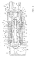
- FIG. 1 is a sectional view of a starter magnet switch 1 according to the present invention.
- a housing 2 of switch 1 has a cylindrical portion 2a and a disk-shaped flange portion 2b formed at one end of the cylindrical portion 2a and bent inward.
- a coil unit 3 includes a resin bobbin 4 having a cylindrical portion 4a and first and second end faces 4b and 4c formed at the two ends of the cylindrical portion 4a; a holding coil 5 wound on the cylindrical portion 4a of the bobbin 4; and an attracting coil 6.
- first and second cylindrical portions 4d and 4e there are formed first and second cylindrical portions 4d and 4e, between which are formed an annular space F.
- An axially extending first groove 4f is formed in the inner circumference of the cylindrical portion 4a, and a cross-sectional area of the groove 4f is about 0.5 mm2 and a second groove 4g for providing communication between the first groove 4f and the space F is formed at the end face of the first cylindrical portion 4d.
- the sleeve 7 thus constructed has its end portion formed integrally with a flange portion 7a which is bent toward the outer circumference.
- a stationary core 8 has a disk portion 8a, which is arranged at the second end face 4c of the bobbin 4, and a cylindrical portion 8b which extends from the inner circumference of the disk portion 8a along the inner circumference of the sleeve 7.
- the disk portion 8a is formed with three through holes 8c.
- a packing 9 is sandwiched between the first end face 4b of the bobbin 4 and the flange portion 2b of the switch housing 2.
- An O-ring 10 is sandwiched between the flange portion 7a of the sleeve 7 and disk portion 8a of the stationary core 8.
- a plunger 11 is arranged movably in the inner circumference of the sleeve 7.
- a plunger rod 11a has one end fixed to a movable contact 13 through an insulating member 12.
- a small gap B is formed between the outer circumference of the plunger rod 11a and the inner circumference of the cylindrical portion 8b of the stationary core 8.
- a return spring 14 is mounted between the plunger 11 and the stationary core 8.
- a contact pressure spring 15 is mounted between the plunger rod 11a and the insulating member 12.
- a switch cover 16 made of a resin includes a cover portion 16a for accommodating the movable contact 13 within its inner circumference and a fixed portion 16b abutting against the disk portion 8a of the stationary core 8.
- the fixed portion 16b is also formed with three holes 16c which are aligned with the through holes 8c of the disk portion 8a of the stationary core 8.
- First and second fixed contacts 17a and 17b, respectively, are fixed on the switch cover 16 in a sealed fashion by means of an O-ring 18 as to abut against the movable contact 13.
- a packing 19 seals the fixed portion 16b of the switch cover 16 and the open end 2d of the switch housing 2, and the disk portion 8a of the stationary core 8 and the fixed portion 16b of the switch cover 16.
- a bolt 20, a nut 21, and a washer 22 together constitute a first fixing means.
- the bolt 20 has its head 20a inserted into the space F within he first and second cylindrical portions 4d and 4e of the bobbin 4 and its threaded portion 20b projecting to the outside of the switch cover 16 through the through hole 8c of the stationary core 8 and the hole 16c of the switch cover 16.
- Bolt 20, cylindrical insulating bush 23 and the hole 16c of the switch cover 16 are so spaced to form a first air passage G1.
- That side of the disk portion 8a of the stationary core 8, which faces the disk-shaped insulating bush 23b, is formed with a groove 8d for establishing a second air passage G2 for providing communication between the space F and the first air passage G1.
- the outer circumference of the fixed portion 16b of the switch cover 16 is formed with a groove 16d which extends radially outwardly of the washer 22 for establishing a third air passage G3 for communicating with the first air passage G1.
- the first, second, and third air passages G1, G2, and G3 together form an air passage for providing communication between the inside and outside of the switch housing 2.
- a plunger boot 24 has its inner circumference mounted with an allowance on the plunger 11 and its outer circumference sandwiched fixedly between a housing 25 and the switching housing 2 to isolate the housing 25 and the magnet switch 1.
- a plunger chamber C is kept away from oil, water, dust and so on through the opening (although not shown) of the housing 25 in which a pinion 28 and a ring gear 29 mesh with each other.
- a lever 26 engages with the plunger 11.
- a starter motor 27 is equipped with a coil 27a and an armature 27b.
- a pinion 28 engages with the other end of the lever 26 for receiving the bobbins of the starter motor 27 transmitted thereto.
- Reference numeral 29 denotes the ring gear of an internal combustion engine.
- the node between one terminal of the holding coil 5 and one terminal of the attracting coil 6 is connected with a battery 31 through a key switch 30.
- the other terminal of the attracting coil 6 is connected with the coil 27a of the starter motor 27.
- the other terminal of the holding coil 5 is grounded to ground through a shunt coil 27c.
- the first fixed contact 17a is connected directly with the battery 31, whereas the second fixed contact 17b is connected like the one terminal of the attracting coil 6 to the coil 27a.
- Coil 27a is electrically connected with the other terminal 6a of the attracting coil 6, as shown in Figure 2, by connecting the other terminal 6a of the attracting coil 6 with the head 20a of the first bolt 20, the first bolt 20 and the second fixed contact 17b through a metal plate 32, and by connecting the coil 27a of the starter motor 27 with the second fixed contact 17b, as shown in Figure 6.
- a second bolt 20 ⁇ moreover, there are connected one terminal 5a of the holding coil 5 and one terminal of the attracting coil 6.
- the second bolt 20 ⁇ for fixing the switch cover 16 also acts as the terminal like the first bolt for supplying the electric power to the holding coil 5 and the attracting coil 6.
- the other terminal of the holding coil 5 is connected with a third bolt 20′ through which a lead wire is connected with the shunt coil 27c.
- Bolts 20′ and 20 ⁇ also have their heads (although not shown) disposed in the space F to fix the switch cover 16.
- the bolts 20′ and 20 ⁇ are not formed in their outer circumferences with air passages for providing communication between the outside and the switch housing.
- a contact chamber A in the switch cover 16 communicates with the plunger chamber C via the gap B which is formed between the plunger rod 11a and the cylindrical portion 8b of the stationary core 8.
- This plunger chamber C in turn communicates with the space F between the first and second cylindrical portions 4d and 4e through the gap E1 between the inner circumference 2c of the flange portion 2b of the switch housing 2 and the sleeve 7, the gap E2 (as better seen from Figures 4 and 5) between the first groove 4f of the bobbin 4 and the sleeve 7, and the gap E3 between the second groove 4g of the bobbin 4 and the flange portion 7a of the sleeve 7.
- Space F in turn communicates with a coil chamber D2 through a gap D1 between the second cylindrical portion 4e of the bobbin 4 and the bush 23.
- the space F further communicates with the outside through the first, second, and third air passages G1, G2, and G3.
- the third air passage G3 is directed downward when the starter is mounted.
- the first groove 4f of the bobbin 4 is arranged upward (i.e., in the opposite direction) with respect to the air passage G.
- the ambient air passes through the passage G into the magnet switch 1.
- the passage to the contact chamber A is long enough to include the passages F and E, the plunger chamber C and the passage B so that the water content or dust in the ambient air can be blocked from flowing; into the chamber containing the switch contacts. Even if water should enter from the passage G, it would hardly flow into the plunger chamber C through the passage E and not into the contact chamber A because it is upwardly apart from the passage G.
- the air passage G between the space F and the outside can be formed with remarkable ease by fixing the switch cover 16 on the housing 2 and by making use of the insertion hole of the bolt 20 for connecting the attracting coil 6 and the coil 27a of the starter motor 27.
- the distance between the plunger chamber C and the outside of the magnet switch 1 is short and the volume of the plunger boot 24 is small. Accordingly, upon the plunger's return stroke, water in the outside of the magnet switch 1 may enter directly into the plunger chamber C through the short distance. Since the contact chamber A communicates with the plunger chamber C, water having entered the plunger chamber C moves easily into the contact chamber C. Similarly, dust can easily enter the conduct chamber.
- the passage between the contact chamber A and the outside of the magnet switch 1 is elongated with respect to the prior art by making use of the long passage between the inner circumference of a bobbin 4 and a sleeve 7, and the coil chamber D. Since the outside communicates with the long passage through the coil chamber D and the long passage prevents a high flow resistance to the air, air carrying dust and water droplets is substantially prevented from entering the plunger chamber through the long passage.
- a magnet switch arrangement having a long flow path through which outside air must pass to enter the inner chamber of the switch where its working contacts are located to prevent the accumulation of dust and moisture therein.
- a coil unit (3) having a bobbin (4) is provided within a switch housing (2), the bobbin having a cylindrical portion (4a) and a pair of end faces (4b,4c) formed at both sides of the cylindrical portion.
- a solenoid coil (5,6) is wound on the bobbin's cylindrical portion.
- a coil chamber (D) is formed between the coil unit and the switch housing.
- a cylindrical non-magnetic sleeve (7) isolates the inside from the outside of the coil chamber.
- a plunger having a movable contact is movable inside of the sleeve so that the plunger shifts the pinion toward the ring gear when the solenoid coil is energized.
- a switch cover (16) includes a contact chamber for covering the movable contact. Fixed contacts (17a,17b) are provided on the switch cover for supplying electrical power to be switched.
- a first passage is defined between the contact chamber and the plunger chamber.
- the sleeve and the cylindrical portion of the bobbin define a second passage therebetween which connects the coil chamber on the switch cover side and the plunger chamber.
- a third passage connects the coil chamber with an outside of the switch housing.
Landscapes
- Physics & Mathematics (AREA)
- Electromagnetism (AREA)
- Electromagnets (AREA)
- Push-Button Switches (AREA)
Abstract
Description
- The present invention relates in general to switches used to activate a starting motor of a vehicle.
- Known starter magnet switches are structurally arranged in such a manner that moisture and dust laden air flows from outside of the switch all the way into the innermost cavities thereof which contain the switch contacts. There, dust and water tend to accumulate on the fixed and movable contacts and degrade the performance of the switch. In cold weather, the water on the contacts freezes to ice which can completely prevent electrical contact from being made.
- One known switch arrangement is disclosed in the Open Technical Report of Nippondenso No. 21-039 (issued on January 20, 1981). A hole is formed in a plunger boot of the switch so that a plunger chamber within a coil communicates with the inside of a starter housing through a gap between an inner surface of the coil and an outer surface of the plunger. Accordingly, air compressed within the plunger chamber as a result of movement of a plunger flows into the inside of the starter housing through the gap and the hole of the plunger boot. The distance between the inside of the starter housing and the plunger chamber is short, and especially the length of the hole of the plunger boot is very short. Accordingly, upon the plunger's return stroke, water that has entered the starter housing may enter the plunger chamber through the short gap. Since the contact chamber communicates with the plunger chamber, the volume of the plunger boot and the plunger chamber becomes small when the plunger returns. Water having entered the plunger chamber moves easily into the contact chamber. Similarly, dust can easily enter into the conduct chamber. Water in the contact chamber freezes in cold weather thereby preventing electrical connection between contacts and dust accumulating in the chamber tends to deteriorate performance.
- It is an object of the present invention to provide a magnet starter switch that is not easily deteriorated by water and dust, by providing a structural arrangement that prevents water and dust from entering the contact chamber.
- It is another object of the present invention to provide a structural arrangement for a magnet starter that can be easily manufactured at low cost.
- According to the present invention, the switch is structured so that the passage between the contact chamber and the outside is elongated with respect to prior art devices by making use of a long passage between the inner circumference of a bobbin and a sleeve. The outside communicates with the long passage through a coil chamber. This long passage presents a high flow resistance to the air, air carrying dust and water droplets are substantially prevented from entering the chamber through the long passage.
- More particulary, the invention provides a magnet switch arrangement having a long flow path through which outside air must pass to enter the inner chamber of the switch where its working contacts are located to prevent the accumulation of dust and moisture therein. A coil unit (3) having a bobbin (4) is provided within a switch housing (2), the bobbin having a cylindrical portion (4a) and a pair of end faces (4b,4c) formed at both sides of the cylindrical portion. A solenoid coil (5,6) is wound on the bobbin's cylindrical portion. A coil chamber (D) is formed between the coil unit and the switch housing. A cylindrical non-magnetic sleeve (7) isolates the inside from the outside of the coil chamber. A plunger having a movable contact is movable inside of the sleeve so that the plunger shifts the pinion toward the ring gear when the solenoid coil is energized. A switch cover (16) includes a contact chamber for covering the movable contact. Fixed contacts (17a,17b) are provided on the switch cover for supplying electrical power to be switched. A first passage is defined between the contact chamber and the plunger chamber. The sleeve and the cylindrical portion of the bobbin define a second passage therebetween which connects the coil chamber on the switch cover side and the plunger chamber. A third passage connects the coil chamber with an outside of the switch housing.
-
- Figure 1 is a sectional view showing one embodiment of the starter magnet switch according to the present invention;
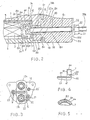
- Figure 2 is a sectional view showing an essential portion of the switch of Figure 1 in an enlarged scale;
- Figure 3 is a side elevation showing the switch of Figure 1;
- Figure 4 is a sectional view showing an essential portion of the bobbin;
- Figure 5 is a sectional view showing an essential portion and taken along line V-V of Figure 1;
- Figure 6 is an electric circuit diagram of a starter;
- Figure 7 is a schematic view showing the switch of Figure 1.
- Figure 8 is a schematic diagram showing the enhanced chamber volumes of the present invention which help to prevent dust and moisture from entering the inner chamber of the switch; and
- Figure 9 is a schematic diagram showing the various chamber volumes according to a prior art device which does not prevent dust and moisture from entering the inner chamber of the switch.
- Figure 1 is a sectional view of a starter magnet switch 1 according to the present invention. A
housing 2 of switch 1 has a cylindrical portion 2a and a disk-shaped flange portion 2b formed at one end of the cylindrical portion 2a and bent inward. Acoil unit 3 includes aresin bobbin 4 having acylindrical portion 4a and first andsecond end faces 4b and 4c formed at the two ends of thecylindrical portion 4a; aholding coil 5 wound on thecylindrical portion 4a of thebobbin 4; and an attractingcoil 6. - As shown in Figures 2 and 4, at the inner and outer circumferences of the
second end face 4c of thebobbin 4, respectively, there are formed first and secondcylindrical portions first groove 4f is formed in the inner circumference of thecylindrical portion 4a, and a cross-sectional area of thegroove 4f is about 0.5 mm² and a second groove 4g for providing communication between thefirst groove 4f and the space F is formed at the end face of the firstcylindrical portion 4d. - A
sleeve 7, made of a non-magnetic material, is arranged to abut against the inner circumference of thecylindrical portion 4a of thebobbin 4 and to face theinner circumference 2c of theflange portion 2b of theswitch housing 2 through a small gap E₁. Thesleeve 7 thus constructed has its end portion formed integrally with aflange portion 7a which is bent toward the outer circumference. A stationary core 8 has adisk portion 8a, which is arranged at thesecond end face 4c of thebobbin 4, and acylindrical portion 8b which extends from the inner circumference of thedisk portion 8a along the inner circumference of thesleeve 7. Thedisk portion 8a is formed with three throughholes 8c. A packing 9 is sandwiched between the first end face 4b of thebobbin 4 and theflange portion 2b of theswitch housing 2. An O-ring 10 is sandwiched between theflange portion 7a of thesleeve 7 anddisk portion 8a of the stationary core 8. - As shown in Figure 2, when the fixed iron core 8 is to be fastened around the
switch housing 2 by fastening theopen end 2d of theswitch housing 2 around the outer circumference of thedisk portion 8a of the stationary core 8, the packing 9, the first and second end faces 4b and 4c and the first cylindrical portion of thebobbin 4, theflange portion 7a of thesleeve 7 and the O-ring 10 are pressed onto theflange portion 2b of theswitch housing 2 by thedisk portion 8a of the stationary core 8. Thesleeve 7 has its inner and outer circumferences spaced by compressing the packing 9 and the O-ring 10 by that pressure. - A
plunger 11 is arranged movably in the inner circumference of thesleeve 7. A plunger rod 11a has one end fixed to amovable contact 13 through aninsulating member 12. A small gap B is formed between the outer circumference of the plunger rod 11a and the inner circumference of thecylindrical portion 8b of the stationary core 8. Areturn spring 14 is mounted between theplunger 11 and the stationary core 8. Acontact pressure spring 15 is mounted between the plunger rod 11a and the insulatingmember 12. Aswitch cover 16 made of a resin includes a cover portion 16a for accommodating themovable contact 13 within its inner circumference and a fixedportion 16b abutting against thedisk portion 8a of the stationary core 8. The fixedportion 16b is also formed with threeholes 16c which are aligned with the throughholes 8c of thedisk portion 8a of the stationary core 8. - First and second
fixed contacts switch cover 16 in a sealed fashion by means of an O-ring 18 as to abut against themovable contact 13. Apacking 19 seals the fixedportion 16b of theswitch cover 16 and theopen end 2d of theswitch housing 2, and thedisk portion 8a of the stationary core 8 and the fixedportion 16b of theswitch cover 16. Abolt 20, anut 21, and awasher 22 together constitute a first fixing means. Thebolt 20 has its head 20a inserted into the space F within he first and secondcylindrical portions bobbin 4 and its threaded portion 20b projecting to the outside of theswitch cover 16 through the throughhole 8c of the stationary core 8 and thehole 16c of theswitch cover 16. By fitting thewasher 2 on the threaded portion 20b and fastening it by thenut 21, theswitch cover 16 is pressed and fixed on the stationary core 8. Cylindrical and circular insulatingbushes 23a and 23b, respectively, insulate thebolt 20 and the stationary core 8, respectively. -
Bolt 20, cylindrical insulatingbush 23 and thehole 16c of theswitch cover 16 are so spaced to form a first air passage G₁. That side of thedisk portion 8a of the stationary core 8, which faces the disk-shaped insulatingbush 23b, is formed with a groove 8d for establishing a second air passage G₂ for providing communication between the space F and the first air passage G₁. The outer circumference of the fixedportion 16b of theswitch cover 16 is formed with agroove 16d which extends radially outwardly of thewasher 22 for establishing a third air passage G₃ for communicating with the first air passage G₁. Thus, the first, second, and third air passages G₁, G₂, and G₃ together form an air passage for providing communication between the inside and outside of theswitch housing 2. - A
plunger boot 24 has its inner circumference mounted with an allowance on theplunger 11 and its outer circumference sandwiched fixedly between ahousing 25 and the switchinghousing 2 to isolate thehousing 25 and the magnet switch 1. By theplunger boot 24, moreover, a plunger chamber C is kept away from oil, water, dust and so on through the opening (although not shown) of thehousing 25 in which apinion 28 and aring gear 29 mesh with each other. Alever 26 engages with theplunger 11. - The overall electric circuit of the starter will be described with reference to Figure 6. A
starter motor 27 is equipped with a coil 27a and anarmature 27b. Apinion 28 engages with the other end of thelever 26 for receiving the bobbins of thestarter motor 27 transmitted thereto.Reference numeral 29 denotes the ring gear of an internal combustion engine. - The node between one terminal of the holding
coil 5 and one terminal of the attractingcoil 6 is connected with a battery 31 through akey switch 30. The other terminal of the attractingcoil 6 is connected with the coil 27a of thestarter motor 27. The other terminal of the holdingcoil 5 is grounded to ground through a shunt coil 27c. The firstfixed contact 17a is connected directly with the battery 31, whereas the secondfixed contact 17b is connected like the one terminal of the attractingcoil 6 to the coil 27a. - Coil 27a is electrically connected with the
other terminal 6a of the attractingcoil 6, as shown in Figure 2, by connecting theother terminal 6a of the attractingcoil 6 with the head 20a of thefirst bolt 20, thefirst bolt 20 and the secondfixed contact 17b through ametal plate 32, and by connecting the coil 27a of thestarter motor 27 with the secondfixed contact 17b, as shown in Figure 6. With asecond bolt 20˝, moreover, there are connected one terminal 5a of the holdingcoil 5 and one terminal of the attractingcoil 6. By connecting the battery 31 with thatsecond bolt 20˝ through thekey switch 30, as shown in Figure 6, thesecond bolt 20˝ for fixing theswitch cover 16 also acts as the terminal like the first bolt for supplying the electric power to the holdingcoil 5 and the attractingcoil 6. - The other terminal of the holding
coil 5 is connected with athird bolt 20′ through which a lead wire is connected with the shunt coil 27c.Bolts 20′ and 20˝ also have their heads (although not shown) disposed in the space F to fix theswitch cover 16. Incidentally, thebolts 20′ and 20˝ are not formed in their outer circumferences with air passages for providing communication between the outside and the switch housing. - The operations of the magnet starter switch will now be described. When
key switch 30 is closed, current flows from the battery 31 via thesecond bolt 20˝ to the holdingcoil 5 and the attractingcoil 6 to attract theplunger 11. At this time, the current having passed through the holdingcoil 5 flows through the shunt coil 27c via thethird bolt 20′. As theplunger 11 moves, thepinion 28 comes into meshing engagement with thering gear 29 through thelever 26. Themovable contact 13 comes into abutment against the first and secondfixed contacts starter motor 27 with the current of the battery 31 so that thearmature 27b and accordingly thepinion 28 rotates to start the internal combustion engine. Since, at this time, the secondfixed contact 17b and thefirst bolt 20 are connected, the two terminals of the attractingcoil 6 are at the same potential and there is no current flowing therebetween. - The invention will now be described with reference to Figures 1 and 7. A contact chamber A in the
switch cover 16 communicates with the plunger chamber C via the gap B which is formed between the plunger rod 11a and thecylindrical portion 8b of the stationary core 8. This plunger chamber C in turn communicates with the space F between the first and secondcylindrical portions inner circumference 2c of theflange portion 2b of theswitch housing 2 and thesleeve 7, the gap E2 (as better seen from Figures 4 and 5) between thefirst groove 4f of thebobbin 4 and thesleeve 7, and the gap E3 between the second groove 4g of thebobbin 4 and theflange portion 7a of thesleeve 7. Space F in turn communicates with a coil chamber D2 through a gap D1 between the secondcylindrical portion 4e of thebobbin 4 and thebush 23. The space F further communicates with the outside through the first, second, and third air passages G₁, G₂, and G₃. - The third air passage G₃ is directed downward when the starter is mounted. At this time, the
first groove 4f of thebobbin 4 is arranged upward (i.e., in the opposite direction) with respect to the air passage G. With this structure thus far described, when theplunger 11 is attracted in the operation of the magnet switch 1, the air in the contact chamber A and the plunger chamber C is compressed so that the compressed air is released through the passages B, C, D, E, F, and G to the outside. This compression of air prevents theplunger boot 24 and the packing 19 from coming out. Since, on the other hand, the air heated to have an increased pressure by thecoil 3 is also released from the passages F and G, the aforementioned seals or the like are prevented from coming out. - When the magnet switch 1 is turned off to return the
plunger 11, on the contrary, the ambient air passes through the passage G into the magnet switch 1. However, the passage to the contact chamber A is long enough to include the passages F and E, the plunger chamber C and the passage B so that the water content or dust in the ambient air can be blocked from flowing; into the chamber containing the switch contacts. Even if water should enter from the passage G, it would hardly flow into the plunger chamber C through the passage E and not into the contact chamber A because it is upwardly apart from the passage G. - Furthermore, the air passage G between the space F and the outside can be formed with remarkable ease by fixing the
switch cover 16 on thehousing 2 and by making use of the insertion hole of thebolt 20 for connecting the attractingcoil 6 and the coil 27a of thestarter motor 27. When theplunger 11 moves toward the fixedcontacts plunger 11 flows into the outside of the magnet switch 1 through the gap between thesleeve 7 and theplunger 11, and the space within theplunger boot 24. Then themovable contact 13 comes into abutment against the first and secondfixed contacts plunger boot 24 and the plunger chamber C becomes smallest, as shown in Figure 8 (the invention) and Figure 9 (prior art). - In the prior art as shown in Figure 9, the distance between the plunger chamber C and the outside of the magnet switch 1 is short and the volume of the
plunger boot 24 is small. Accordingly, upon the plunger's return stroke, water in the outside of the magnet switch 1 may enter directly into the plunger chamber C through the short distance. Since the contact chamber A communicates with the plunger chamber C, water having entered the plunger chamber C moves easily into the contact chamber C. Similarly, dust can easily enter the conduct chamber. - As shown in Figure 8, the passage between the contact chamber A and the outside of the magnet switch 1 is elongated with respect to the prior art by making use of the long passage between the inner circumference of a
bobbin 4 and asleeve 7, and the coil chamber D. Since the outside communicates with the long passage through the coil chamber D and the long passage prevents a high flow resistance to the air, air carrying dust and water droplets is substantially prevented from entering the plunger chamber through the long passage. - While this invention has been described in connection with what is presently considered to be the most practical and preferred embodiment, it is to be understood that the invention is not limited to the disclosed embodiment, but, on the contrary, is intended to cover various modifications and equivalent arrangements included within the spirit and scope of the appended claims.
- A magnet switch arrangement having a long flow path through which outside air must pass to enter the inner chamber of the switch where its working contacts are located to prevent the accumulation of dust and moisture therein. A coil unit (3) having a bobbin (4) is provided within a switch housing (2), the bobbin having a cylindrical portion (4a) and a pair of end faces (4b,4c) formed at both sides of the cylindrical portion. A solenoid coil (5,6) is wound on the bobbin's cylindrical portion. A coil chamber (D) is formed between the coil unit and the switch housing. A cylindrical non-magnetic sleeve (7) isolates the inside from the outside of the coil chamber. A plunger having a movable contact is movable inside of the sleeve so that the plunger shifts the pinion toward the ring gear when the solenoid coil is energized. A switch cover (16) includes a contact chamber for covering the movable contact. Fixed contacts (17a,17b) are provided on the switch cover for supplying electrical power to be switched. A first passage is defined between the contact chamber and the plunger chamber. The sleeve and the cylindrical portion of the bobbin define a second passage therebetween which connects the coil chamber on the switch cover side and the plunger chamber. A third passage connects the coil chamber with an outside of the switch housing.
Claims (15)
a cylindrical switch housing;
a coil unit having a bobbin provided within said switch housing, said bobbin comprising a cylindrical portion and a pair of end faces formed at both sides of said cylindrical portion, and a solenoid coil wound on said cylindrical portion of said bobbin;
a coil chamber formed between said coil unit and said switch housing;
a cylindrical non-magnetic sleeve touching an inner surface of said cylindrical portion of said bobbin so that said sleeve isolates between an inside and outside of said coil chamber;
a plunger having a movable contact and arranged movably inside of said sleeve so that said plunger shifts said pinion toward said ring gear when said solenoid coil is energized;
a switch cover comprising a contact chamber for covering said movable contact;
a fixed contact provided on said switch cover, and for supplying electrical power to said starter motor from said battery when said movable contact closes said fixed contact;
means, including said plunger, for defining a first passage between said contact chamber and said plunger chamber;
said sleeve and said cylindrical portion of said bobbin defining a second passage therebetween, said second passage connecting said coil chamber on said switch cover side and said plunger chamber on said switch cover opposite side; and
means for defining a third passage connecting said coil chamber with an outside of said switch housing.
a second housing for securing said switch housing; and
an annular plunger boot having an inner part connected to said plunger, and an outer part fixed between said second housing and said switch housing.
Applications Claiming Priority (2)
| Application Number | Priority Date | Filing Date | Title |
|---|---|---|---|
| JP117490/87 | 1987-05-14 | ||
| JP62117490A JPS63280851A (en) | 1987-05-14 | 1987-05-14 | Magnet switch for starter |
Publications (3)
| Publication Number | Publication Date |
|---|---|
| EP0290734A2 true EP0290734A2 (en) | 1988-11-17 |
| EP0290734A3 EP0290734A3 (en) | 1990-07-18 |
| EP0290734B1 EP0290734B1 (en) | 1994-12-14 |
Family
ID=14713013
Family Applications (1)
| Application Number | Title | Priority Date | Filing Date |
|---|---|---|---|
| EP88103542A Expired - Lifetime EP0290734B1 (en) | 1987-05-14 | 1988-03-07 | Magnet switch for a starter |
Country Status (4)
| Country | Link |
|---|---|
| US (1) | US4887056A (en) |
| EP (1) | EP0290734B1 (en) |
| JP (1) | JPS63280851A (en) |
| DE (1) | DE3852424T2 (en) |
Cited By (4)
| Publication number | Priority date | Publication date | Assignee | Title |
|---|---|---|---|---|
| WO2010049400A1 (en) * | 2008-10-27 | 2010-05-06 | Robert Bosch Gmbh | Solenoid switch |
| CN105065169A (en) * | 2013-12-11 | 2015-11-18 | 罗伯特·博世有限公司 | Electromagnetic switch, especially the starter relay for a starting device |
| EP2975627A1 (en) * | 2014-07-14 | 2016-01-20 | Bosch Automotive Products (Changsha) Co., Ltd | Solenoid switch and vehicle starter motor |
| WO2018015653A1 (en) * | 2016-07-21 | 2018-01-25 | Valeo Equipements Electriques Moteur | Starter contactor comprising a dust protection device, and starter provided with such a contactor |
Families Citing this family (12)
| Publication number | Priority date | Publication date | Assignee | Title |
|---|---|---|---|---|
| US5132653A (en) * | 1987-09-09 | 1992-07-21 | Yoshiteru Nakatake | Electromagnetic switch |
| JP2760082B2 (en) * | 1989-09-19 | 1998-05-28 | 株式会社デンソー | Starter |
| JP3324145B2 (en) * | 1992-07-31 | 2002-09-17 | 株式会社デンソー | magnetic switch |
| FR2751124B1 (en) * | 1996-07-10 | 1998-09-18 | Valeo Equip Electr Moteur | STARTER OF A MOTOR VEHICLE COMPRISING IMPROVED MEANS OF ELECTRICAL CONNECTION OF THE CONTACTOR |
| JP2000322999A (en) * | 1999-05-12 | 2000-11-24 | Mitsubishi Electric Corp | Magnetic switch for starter |
| JP2003208840A (en) * | 2002-01-10 | 2003-07-25 | Denso Corp | Electromagnetic switch for starter |
| DE102007053417A1 (en) * | 2007-11-09 | 2009-05-14 | Robert Bosch Gmbh | Electromagnetic switch for electric machine |
| KR101004465B1 (en) * | 2008-09-05 | 2010-12-31 | 엘에스산전 주식회사 | relay |
| DE102009027844A1 (en) * | 2009-07-20 | 2011-01-27 | Robert Bosch Gmbh | Switching relay with contact tearing device |
| DE102010003823B4 (en) * | 2010-04-09 | 2019-03-28 | Seg Automotive Germany Gmbh | Cover ring for starting device |
| FR3054382A1 (en) * | 2016-07-21 | 2018-01-26 | Valeo Equipements Electriques Moteur | STARTER CONTACTOR COMPRISING A PROTECTION DEVICE, AND STARTER COMPRISING SUCH A CONTACTOR |
| DE102018211137B4 (en) * | 2018-07-05 | 2023-11-23 | Bayerische Motoren Werke Aktiengesellschaft | Methods and systems for starter actuation |
Family Cites Families (6)
| Publication number | Priority date | Publication date | Assignee | Title |
|---|---|---|---|---|
| JPS53156056U (en) * | 1977-05-13 | 1978-12-07 | ||
| JPS602901B2 (en) * | 1978-04-19 | 1985-01-24 | 株式会社クボタ | Two-component injection device |
| DE2835407C2 (en) * | 1978-08-12 | 1987-01-15 | Robert Bosch Gmbh, 7000 Stuttgart | Electromagnetic switch, especially for starting devices of internal combustion engines |
| US4404533A (en) * | 1981-03-27 | 1983-09-13 | Honda Giken Kogyo Kabushiki Kaisha | Electromagnetic switch device |
| US4579010A (en) * | 1984-09-26 | 1986-04-01 | General Motors Corporation | Shift mechanism for engine starting apparatus |
| JPH0643979Y2 (en) * | 1985-07-19 | 1994-11-14 | 三菱電機株式会社 | Electromagnetic switch |
-
1987
- 1987-05-14 JP JP62117490A patent/JPS63280851A/en active Granted
-
1988
- 1988-03-02 US US07/163,099 patent/US4887056A/en not_active Expired - Fee Related
- 1988-03-07 EP EP88103542A patent/EP0290734B1/en not_active Expired - Lifetime
- 1988-03-07 DE DE3852424T patent/DE3852424T2/en not_active Expired - Fee Related
Cited By (8)
| Publication number | Priority date | Publication date | Assignee | Title |
|---|---|---|---|---|
| WO2010049400A1 (en) * | 2008-10-27 | 2010-05-06 | Robert Bosch Gmbh | Solenoid switch |
| CN105065169A (en) * | 2013-12-11 | 2015-11-18 | 罗伯特·博世有限公司 | Electromagnetic switch, especially the starter relay for a starting device |
| CN105065169B (en) * | 2013-12-11 | 2018-01-30 | 罗伯特·博世有限公司 | Electromagnetic switch, the starter relay in particular for starting device |
| EP2975627A1 (en) * | 2014-07-14 | 2016-01-20 | Bosch Automotive Products (Changsha) Co., Ltd | Solenoid switch and vehicle starter motor |
| CN105470049A (en) * | 2014-07-14 | 2016-04-06 | 博世汽车部件(长沙)有限公司 | Electromagnetic switch and vehicle starter |
| CN105470049B (en) * | 2014-07-14 | 2019-05-17 | 索恩格汽车部件(中国)有限公司 | Electromagnetic switch and vehicle starter |
| WO2018015653A1 (en) * | 2016-07-21 | 2018-01-25 | Valeo Equipements Electriques Moteur | Starter contactor comprising a dust protection device, and starter provided with such a contactor |
| FR3054368A1 (en) * | 2016-07-21 | 2018-01-26 | Valeo Equipements Electriques Moteur | STARTER CONTACTOR COMPRISING A DUST PROTECTION DEVICE, AND STARTER EQUIPPED WITH SUCH A CONTACTOR |
Also Published As
| Publication number | Publication date |
|---|---|
| DE3852424T2 (en) | 1995-05-18 |
| US4887056A (en) | 1989-12-12 |
| EP0290734A3 (en) | 1990-07-18 |
| DE3852424D1 (en) | 1995-01-26 |
| JPS63280851A (en) | 1988-11-17 |
| JPH0444108B2 (en) | 1992-07-20 |
| EP0290734B1 (en) | 1994-12-14 |
Similar Documents
| Publication | Publication Date | Title |
|---|---|---|
| US4887056A (en) | Magnet switch for a starter | |
| US5703551A (en) | Starter contactor having an electronic control circuit, and a vehicle starter having such a contactor | |
| US7948338B2 (en) | Electromagnetic switch equipped with built-in electronic control circuit | |
| US5132653A (en) | Electromagnetic switch | |
| US6943655B1 (en) | Direct current contactor assembly | |
| US20020067231A1 (en) | Magnetic switch for starter motor | |
| US4769295A (en) | Battery and switch to be mounted on vehicles | |
| JP4661721B2 (en) | Starter | |
| US7549899B2 (en) | Electromagnetic switch of starter | |
| US7116196B1 (en) | Starter electromagnetic switch | |
| US4862123A (en) | Solenoid for electric starters | |
| US4362051A (en) | Fuel injection nozzle holder for internal combustion engines | |
| US5757256A (en) | Starter and contactor therefor | |
| US3217124A (en) | Solenoid switch having a bridging contact on the solenoid plunger | |
| US5252935A (en) | Electromagnetic switch | |
| JPH05217481A (en) | Starter motor electromagnetic switch | |
| US4707616A (en) | Electric engine starter | |
| JP2005529263A (en) | Electronic module for ignition coil of internal combustion engine | |
| JPH019083Y2 (en) | ||
| JPS6355742B2 (en) | ||
| JPS6111977Y2 (en) | ||
| JPH0784858B2 (en) | Magnet switch for starter | |
| JPH0119303Y2 (en) | ||
| US6222435B1 (en) | Stick coil for igntion systems | |
| GB2229579A (en) | "An electromagnetic switch for controlling the electric starter meter of an internal combustion engine" |
Legal Events
| Date | Code | Title | Description |
|---|---|---|---|
| PUAI | Public reference made under article 153(3) epc to a published international application that has entered the european phase |
Free format text: ORIGINAL CODE: 0009012 |
|
| AK | Designated contracting states |
Kind code of ref document: A2 Designated state(s): DE FR GB IT |
|
| PUAL | Search report despatched |
Free format text: ORIGINAL CODE: 0009013 |
|
| AK | Designated contracting states |
Kind code of ref document: A3 Designated state(s): DE FR GB IT |
|
| 17P | Request for examination filed |
Effective date: 19900704 |
|
| 17Q | First examination report despatched |
Effective date: 19920910 |
|
| GRAA | (expected) grant |
Free format text: ORIGINAL CODE: 0009210 |
|
| AK | Designated contracting states |
Kind code of ref document: B1 Designated state(s): DE FR GB IT |
|
| REF | Corresponds to: |
Ref document number: 3852424 Country of ref document: DE Date of ref document: 19950126 |
|
| ITF | It: translation for a ep patent filed | ||
| ET | Fr: translation filed | ||
| PLBE | No opposition filed within time limit |
Free format text: ORIGINAL CODE: 0009261 |
|
| STAA | Information on the status of an ep patent application or granted ep patent |
Free format text: STATUS: NO OPPOSITION FILED WITHIN TIME LIMIT |
|
| 26N | No opposition filed | ||
| PGFP | Annual fee paid to national office [announced via postgrant information from national office to epo] |
Ref country code: GB Payment date: 19970226 Year of fee payment: 10 |
|
| REG | Reference to a national code |
Ref country code: GB Ref legal event code: 746 Effective date: 19970212 |
|
| PGFP | Annual fee paid to national office [announced via postgrant information from national office to epo] |
Ref country code: FR Payment date: 19970313 Year of fee payment: 10 |
|
| PGFP | Annual fee paid to national office [announced via postgrant information from national office to epo] |
Ref country code: DE Payment date: 19970314 Year of fee payment: 10 |
|
| ITPR | It: changes in ownership of a european patent |
Owner name: OFFERTA DI LICENZA AL PUBBLICO;AL PUBBLICO |
|
| ITPR | It: changes in ownership of a european patent |
Owner name: OFFERTA DI LICENZA AL PUBBLICO;PUBBLICO |
|
| PG25 | Lapsed in a contracting state [announced via postgrant information from national office to epo] |
Ref country code: GB Free format text: LAPSE BECAUSE OF NON-PAYMENT OF DUE FEES Effective date: 19980307 |
|
| PG25 | Lapsed in a contracting state [announced via postgrant information from national office to epo] |
Ref country code: FR Free format text: THE PATENT HAS BEEN ANNULLED BY A DECISION OF A NATIONAL AUTHORITY Effective date: 19980331 |
|
| GBPC | Gb: european patent ceased through non-payment of renewal fee |
Effective date: 19980307 |
|
| PG25 | Lapsed in a contracting state [announced via postgrant information from national office to epo] |
Ref country code: DE Free format text: LAPSE BECAUSE OF NON-PAYMENT OF DUE FEES Effective date: 19981201 |
|
| REG | Reference to a national code |
Ref country code: FR Ref legal event code: ST |
|
| PG25 | Lapsed in a contracting state [announced via postgrant information from national office to epo] |
Ref country code: IT Free format text: LAPSE BECAUSE OF NON-PAYMENT OF DUE FEES;WARNING: LAPSES OF ITALIAN PATENTS WITH EFFECTIVE DATE BEFORE 2007 MAY HAVE OCCURRED AT ANY TIME BEFORE 2007. THE CORRECT EFFECTIVE DATE MAY BE DIFFERENT FROM THE ONE RECORDED. Effective date: 20050307 |