EP0290234B1 - Breakaway mirror retention means - Google Patents
Breakaway mirror retention means Download PDFInfo
- Publication number
- EP0290234B1 EP0290234B1 EP88304025A EP88304025A EP0290234B1 EP 0290234 B1 EP0290234 B1 EP 0290234B1 EP 88304025 A EP88304025 A EP 88304025A EP 88304025 A EP88304025 A EP 88304025A EP 0290234 B1 EP0290234 B1 EP 0290234B1
- Authority
- EP
- European Patent Office
- Prior art keywords
- spring
- mirror assembly
- control lever
- assembly according
- backing plate
- Prior art date
- Legal status (The legal status is an assumption and is not a legal conclusion. Google has not performed a legal analysis and makes no representation as to the accuracy of the status listed.)
- Expired - Lifetime
Links
- 230000014759 maintenance of location Effects 0.000 title 1
- 230000000717 retained effect Effects 0.000 claims description 3
- 230000000712 assembly Effects 0.000 description 1
- 238000000429 assembly Methods 0.000 description 1
Images

Classifications
-
- B—PERFORMING OPERATIONS; TRANSPORTING
- B60—VEHICLES IN GENERAL
- B60R—VEHICLES, VEHICLE FITTINGS, OR VEHICLE PARTS, NOT OTHERWISE PROVIDED FOR
- B60R1/00—Optical viewing arrangements; Real-time viewing arrangements for drivers or passengers using optical image capturing systems, e.g. cameras or video systems specially adapted for use in or on vehicles
- B60R1/02—Rear-view mirror arrangements
- B60R1/06—Rear-view mirror arrangements mounted on vehicle exterior
- B60R1/062—Rear-view mirror arrangements mounted on vehicle exterior with remote control for adjusting position
- B60R1/064—Rear-view mirror arrangements mounted on vehicle exterior with remote control for adjusting position by manually powered actuators
- B60R1/066—Rear-view mirror arrangements mounted on vehicle exterior with remote control for adjusting position by manually powered actuators for adjusting the mirror relative to its housing
Definitions
- This invention relates to a rear vision mirror assembly of the break-away type, having a mounting base base portion connected to a pivoted portion by pivot means comprising projecting lugs on one portion which releasably engage socket portions of the other portion and a spring extending between said portions urging said lugs into engagement with said socket portions;
- the pivoted portion comprising a cover, a mirror backing plate, universal pivot means between the cover and backing plate, a mirror on the backing plate, a control lever guide on the backing plate which extends towards the base portion;
- the base portion comprising a socket wall, a control lever having a lever arm extending through the socket wall and carrying a ball intermediate its ends which bears against said socket wall.
- a mirror assembly of the type is disclosed in DE-A 3 434 959.
- the head on the control lever disengages from the control lever guide during break-away and a separate guide member is used to ensure re-engagement.
- control lever guide has retaining portions adjacent its end, and a head on an end of said lever arm is freely movable in said guide but retained therein by walls thereof and said retaining portions.
- the drawings show a break-away rear vision mirror assembly comprising a mounting base portion 11 which is arranged to be secured to an external panel of a vehicle, and has projecting inwardly therefrom a control lever 12.
- the control lever 12 has a ball 13 which is urged into engagement with a wall of a socket 14 by means of a saddle 15 which has two hook ends 16 coupled to respective ends of a U-shaped spring 17 which is carried and guided by arcuate spring track walls in a spring plate 18 secured to a cover 19 of a pivoted portion 20 of mirror assembly 10.
- the spring track walls guide the spring for only its curved portion, as shown in Figure 1, so that, on break-away, the ends of the spring can change position.
- the pivoted portion 20 comprises a support plate 24 also secured to the cover 19 and having a universal mounting ball 25 on which is mounted a mirror backing plate 26 for universal pivotal movement, the backing plate 26 supporting a mirror 27.
- the mirror backing plate 26 however is monolithic with a guide for the control lever, which comprises channel walls 29 (not shown in Figure 1) which terminate at their mounting base ends in inturned nibs 30.
- the walls 29 have flanges 31 extending along their outer edges, so that the channel is narrow- mouthed, and the flanges 31 and inturned nibs 30 prevent withdrawal of a T-head 32 on inner end of arm 33 of the control lever 12. (The ball 13 is an arm 33). This will positively retain the pivoted portion 20 of the mirror assembly to the control lever 12 under all conditions of deflection other than severe impact or disintegration of the assembly.
- the mounting base portion 11 is provided with four outwardly projecting V-shaped locating lugs 36 (not shown in Figure 2) and these enter correspnding sockets 37 at the mounting end of the pivoted portion 20, the sockets 37 being in the cover walls.
- the pivoted portion 20 is retained in its normal position by means of the Ushaped spring 17 which extends through the adjacent walls of the mounting base 11 and cover 19, and engage the saddle 15, which can (in some instances) be a length of thick wire.
- the saddle 15 has legs 39 which extend through large apertures in the mounting base portion 11 so that they can tilt. Because the spring 17 is tensioned upon deflection, the mirror assembly is guided back to its correct position so that the locating lugs 36 re-enter the sockets 37. The spring 17, the Thead 32 and channel walls 29, and the legs 39 all perform part of the guide function.
Landscapes
- Engineering & Computer Science (AREA)
- Multimedia (AREA)
- Mechanical Engineering (AREA)
- Rear-View Mirror Devices That Are Mounted On The Exterior Of The Vehicle (AREA)
Description
- This invention relates to a rear vision mirror assembly of the break-away type, having a mounting base base portion connected to a pivoted portion by pivot means comprising projecting lugs on one portion which releasably engage socket portions of the other portion and a spring extending between said portions urging said lugs into engagement with said socket portions; the pivoted portion comprising a cover, a mirror backing plate, universal pivot means between the cover and backing plate, a mirror on the backing plate, a control lever guide on the backing plate which extends towards the base portion; and the base portion comprising a socket wall, a control lever having a lever arm extending through the socket wall and carrying a ball intermediate its ends which bears against said socket wall.
- A mirror assembly of the type is disclosed in DE-A 3 434 959. The head on the control lever disengages from the control lever guide during break-away and a separate guide member is used to ensure re-engagement.
- According to the invention, in a mirror assembly of the type described above, the control lever guide has retaining portions adjacent its end, and a head on an end of said lever arm is freely movable in said guide but retained therein by walls thereof and said retaining portions.
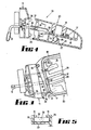
- An embodiment of the invention is described below with reference to the accompanying drawings in which:
- Figure 1 is a diagrammatic elevation of a break-away rear vision mirror assembly with the mirror and its backing plate removed;
- Figure 2 is a section on line 2-2 of Figure 1;
- Figure 3 is a fragmentary view similar to Figure 1, showing the pivoted portion deflected upwardly;
- Figure 4 is a view similar to Figure 2 but with the pivoted portion deflected rearwardly; and Figure 5 is a section on line 5-5 of Figure 4 but drawn to a larger scale.
- The drawings show a break-away rear vision mirror assembly comprising a
mounting base portion 11 which is arranged to be secured to an external panel of a vehicle, and has projecting inwardly therefrom acontrol lever 12. Thecontrol lever 12 has aball 13 which is urged into engagement with a wall of asocket 14 by means of asaddle 15 which has twohook ends 16 coupled to respective ends of a U-shapedspring 17 which is carried and guided by arcuate spring track walls in aspring plate 18 secured to acover 19 of a pivotedportion 20 ofmirror assembly 10. The spring track walls guide the spring for only its curved portion, as shown in Figure 1, so that, on break-away, the ends of the spring can change position. - The pivoted
portion 20 comprises asupport plate 24 also secured to thecover 19 and having auniversal mounting ball 25 on which is mounted amirror backing plate 26 for universal pivotal movement, thebacking plate 26 supporting amirror 27. - The
mirror backing plate 26 however is monolithic with a guide for the control lever, which comprises channel walls 29 (not shown in Figure 1) which terminate at their mounting base ends in inturnednibs 30. Thewalls 29 haveflanges 31 extending along their outer edges, so that the channel is narrow- mouthed, and theflanges 31 and inturnednibs 30 prevent withdrawal of a T-head 32 on inner end ofarm 33 of thecontrol lever 12. (Theball 13 is an arm 33). This will positively retain thepivoted portion 20 of the mirror assembly to thecontrol lever 12 under all conditions of deflection other than severe impact or disintegration of the assembly. - The
mounting base portion 11 is provided with four outwardly projecting V-shaped locating lugs 36 (not shown in Figure 2) and these enter correspndingsockets 37 at the mounting end of thepivoted portion 20, thesockets 37 being in the cover walls. The pivotedportion 20 is retained in its normal position by means of theUshaped spring 17 which extends through the adjacent walls of themounting base 11 andcover 19, and engage thesaddle 15, which can (in some instances) be a length of thick wire. - However, in this embodiment, as more particularly shown in Figure 1, the
saddle 15 haslegs 39 which extend through large apertures in themounting base portion 11 so that they can tilt. Because thespring 17 is tensioned upon deflection, the mirror assembly is guided back to its correct position so that the locatinglugs 36 re-enter thesockets 37. Thespring 17, theThead 32 andchannel walls 29, and thelegs 39 all perform part of the guide function. - Although the invention will be seen to be very simple, it nevertheless results in an effective repositioning of the mirror assembly under a much wider range of conditions than exists with prior art mirror assemblies.
Claims (6)
Applications Claiming Priority (2)
| Application Number | Priority Date | Filing Date | Title |
|---|---|---|---|
| AUPI172187 | 1987-05-04 | ||
| AU1721/87 | 1987-05-04 |
Publications (3)
| Publication Number | Publication Date |
|---|---|
| EP0290234A2 EP0290234A2 (en) | 1988-11-09 |
| EP0290234A3 EP0290234A3 (en) | 1989-10-25 |
| EP0290234B1 true EP0290234B1 (en) | 1990-10-24 |
Family
ID=3772146
Family Applications (1)
| Application Number | Title | Priority Date | Filing Date |
|---|---|---|---|
| EP88304025A Expired - Lifetime EP0290234B1 (en) | 1987-05-04 | 1988-05-04 | Breakaway mirror retention means |
Country Status (4)
| Country | Link |
|---|---|
| EP (1) | EP0290234B1 (en) |
| AU (1) | AU600126B2 (en) |
| ES (1) | ES2018610B3 (en) |
| NZ (1) | NZ224443A (en) |
Families Citing this family (1)
| Publication number | Priority date | Publication date | Assignee | Title |
|---|---|---|---|---|
| AU617450B2 (en) * | 1988-05-05 | 1991-11-28 | Britax Rainsfords Pty Ltd | Break-away mirror mechanism |
Family Cites Families (6)
| Publication number | Priority date | Publication date | Assignee | Title |
|---|---|---|---|---|
| DE2436339C2 (en) * | 1974-07-27 | 1983-11-24 | Daimler-Benz Ag, 7000 Stuttgart | Exterior rear-view mirror to be attached to the side of the vehicle |
| DE2856612C2 (en) * | 1978-12-29 | 1983-12-01 | Hagus C. Luchtenberg Gmbh & Co Kg, 5650 Solingen | Vehicle exterior mirror |
| JPS56124528A (en) * | 1980-03-05 | 1981-09-30 | Nissan Motor Co Ltd | Door mirror |
| US4464017A (en) * | 1981-08-31 | 1984-08-07 | Ichikoh Industries Limited | Remotely controlled mirror apparatus for motor vehicles |
| US4636045A (en) * | 1983-09-01 | 1987-01-13 | Kabushiki Kaisha Tokai Rika Denki Seisakusho | Manual adjusting device for tiltable outer mirror |
| DE3434959A1 (en) * | 1984-09-22 | 1986-04-17 | Reitter & Schefenacker Kg, 7300 Esslingen | REMOTE CONTROLLED EXTERNAL REAR VIEW MIRROR FOR VEHICLES, IN PARTICULAR MOTOR VEHICLES |
-
1988
- 1988-05-02 NZ NZ224443A patent/NZ224443A/en unknown
- 1988-05-03 AU AU15540/88A patent/AU600126B2/en not_active Ceased
- 1988-05-04 EP EP88304025A patent/EP0290234B1/en not_active Expired - Lifetime
- 1988-05-04 ES ES88304025T patent/ES2018610B3/en not_active Expired - Lifetime
Also Published As
| Publication number | Publication date |
|---|---|
| NZ224443A (en) | 1989-05-29 |
| EP0290234A3 (en) | 1989-10-25 |
| AU1554088A (en) | 1988-11-10 |
| ES2018610B3 (en) | 1991-04-16 |
| AU600126B2 (en) | 1990-08-02 |
| EP0290234A2 (en) | 1988-11-09 |
Similar Documents
| Publication | Publication Date | Title |
|---|---|---|
| US7481596B2 (en) | Connector which is used to join a windscreen wiper arm to a wiper blade | |
| US7316047B2 (en) | Connector linking a wiper arm to a wiper blade | |
| US6332806B1 (en) | Fixing apparatus | |
| US6135905A (en) | Derailleur cable router with a cable housing support that pivots in multiple directions | |
| US5709358A (en) | Installing structure of cluster module | |
| EP0169734B1 (en) | A rear view mirror assembly | |
| CA2231884A1 (en) | Vehicle seat track assembly | |
| EP0073289B1 (en) | Remotely controlled mirror apparatus for motor vehicles | |
| EP0290233B1 (en) | Breakaway mirror spring means | |
| PL327869A1 (en) | Utility vehicle with a mirror in its fron portion | |
| US5105683A (en) | Device for releasably securing a shoe to a bicycle pedal | |
| GB2102672A (en) | Means for connecting wiper arm to wiper blade | |
| US6058555A (en) | Wiper blade with wind-deflecting surface for windshield wiper systems of motor vehicles | |
| US20020192017A1 (en) | Wiper blade coupler with shim | |
| EP0285262B1 (en) | Wiperblade of windshield wiper | |
| US5023972A (en) | Spare wiper element | |
| EP0341016B1 (en) | Break-away mirror mechanism | |
| US4909470A (en) | Overhead console with breakaway mount | |
| US5065474A (en) | Multiple position adapter for mounting wiper-blade assembly on wiper arm | |
| US5169189A (en) | Device for holding a decorative cover on a bumper | |
| US5074653A (en) | External rear view mirror for motor vehicles | |
| EP0290234A2 (en) | Breakaway mirror retention means | |
| US4802257A (en) | Wiper blade for cleaning window panes of motor vehicles | |
| GB1600425A (en) | Motor vehicle rear-view mirrors | |
| DE3760219D1 (en) | Framework of motorcar seat or the like |
Legal Events
| Date | Code | Title | Description |
|---|---|---|---|
| PUAI | Public reference made under article 153(3) epc to a published international application that has entered the european phase |
Free format text: ORIGINAL CODE: 0009012 |
|
| AK | Designated contracting states |
Kind code of ref document: A2 Designated state(s): DE ES FR GB |
|
| PUAL | Search report despatched |
Free format text: ORIGINAL CODE: 0009013 |
|
| AK | Designated contracting states |
Kind code of ref document: A3 Designated state(s): DE ES FR GB |
|
| 17P | Request for examination filed |
Effective date: 19891107 |
|
| 17Q | First examination report despatched |
Effective date: 19900312 |
|
| GRAA | (expected) grant |
Free format text: ORIGINAL CODE: 0009210 |
|
| AK | Designated contracting states |
Kind code of ref document: B1 Designated state(s): DE ES FR GB |
|
| REF | Corresponds to: |
Ref document number: 3860867 Country of ref document: DE Date of ref document: 19901129 |
|
| ET | Fr: translation filed | ||
| PG25 | Lapsed in a contracting state [announced via postgrant information from national office to epo] |
Ref country code: ES Free format text: LAPSE BECAUSE OF NON-PAYMENT OF DUE FEES Effective date: 19910506 |
|
| PLBE | No opposition filed within time limit |
Free format text: ORIGINAL CODE: 0009261 |
|
| STAA | Information on the status of an ep patent application or granted ep patent |
Free format text: STATUS: NO OPPOSITION FILED WITHIN TIME LIMIT |
|
| 26N | No opposition filed | ||
| PG25 | Lapsed in a contracting state [announced via postgrant information from national office to epo] |
Ref country code: FR Effective date: 19920131 |
|
| PG25 | Lapsed in a contracting state [announced via postgrant information from national office to epo] |
Ref country code: DE Effective date: 19920303 |
|
| REG | Reference to a national code |
Ref country code: FR Ref legal event code: ST |
|
| PG25 | Lapsed in a contracting state [announced via postgrant information from national office to epo] |
Ref country code: GB Effective date: 19920504 |
|
| GBPC | Gb: european patent ceased through non-payment of renewal fee |
Effective date: 19920504 |
|
| REG | Reference to a national code |
Ref country code: ES Ref legal event code: FD2A Effective date: 19990405 |