EP0289937A2 - Dolly frame - Google Patents
Dolly frame Download PDFInfo
- Publication number
- EP0289937A2 EP0289937A2 EP88106799A EP88106799A EP0289937A2 EP 0289937 A2 EP0289937 A2 EP 0289937A2 EP 88106799 A EP88106799 A EP 88106799A EP 88106799 A EP88106799 A EP 88106799A EP 0289937 A2 EP0289937 A2 EP 0289937A2
- Authority
- EP
- European Patent Office
- Prior art keywords
- dolly
- set forth
- crossarm
- leg
- base
- Prior art date
- Legal status (The legal status is an assumption and is not a legal conclusion. Google has not performed a legal analysis and makes no representation as to the accuracy of the status listed.)
- Granted
Links
Images


Classifications
-
- B—PERFORMING OPERATIONS; TRANSPORTING
- B62—LAND VEHICLES FOR TRAVELLING OTHERWISE THAN ON RAILS
- B62B—HAND-PROPELLED VEHICLES, e.g. HAND CARTS OR PERAMBULATORS; SLEDGES
- B62B5/00—Accessories or details specially adapted for hand carts
- B62B5/0083—Wheeled supports connected to the transported object
-
- B—PERFORMING OPERATIONS; TRANSPORTING
- B62—LAND VEHICLES FOR TRAVELLING OTHERWISE THAN ON RAILS
- B62B—HAND-PROPELLED VEHICLES, e.g. HAND CARTS OR PERAMBULATORS; SLEDGES
- B62B3/00—Hand carts having more than one axis carrying transport wheels; Steering devices therefor; Equipment therefor
- B62B3/10—Hand carts having more than one axis carrying transport wheels; Steering devices therefor; Equipment therefor characterised by supports specially adapted to objects of definite shape
- B62B3/104—Hand carts having more than one axis carrying transport wheels; Steering devices therefor; Equipment therefor characterised by supports specially adapted to objects of definite shape the object being of cylindrical shape, e.g. barrels, buckets, dustbins
Definitions
- This invention relates to dollies in general, and more particularly relates to the frame of a dolly that is secured to the bottom of a barrel or tank which is standing on end.
- a dolly is constructed with a base consisting of two elongated plastic elements that are interengaged in a T-configuration, with one element constituting the crossarm and the other element constituting a leg which extends from the center of the crossarm and at right angles thereto.
- the connection between the leg and crossarm permits limited adjustment between these elements so that the drum diameter need not have a close tolerance.
- a metal rod constituting an axle extends lengthwise through the crossarm and mounts wheels at opposite ends thereof. At the end of the leg remote from the crossarm there is a well that receives the stem of a swivel-type wheel unit.
- the front or top of the base is provided with three slots, two being at opposite enlarged ends of the crossarm and the third being at the enlarged end of the leg remote from the crossarm. These slots receive the peripheral bead at the bottom of the drum, which bead is held in the slots by screws that are mounted to the base, with portions of the screw heads overlapping the bead.
- the primary object of the instant invention is to provide an inexpensive dolly that is readily securable to a drum which is standing on end.
- Another object is to provide a dolly of this type that includes a load carrying base constructed of interengaging plastic elements.
- Still another object is to provide a dolly of this type in which there is a wheel axle that extends longitudinally through one of the plastic elements and is disposed for direct support of the drum.
- a further object is to provide a dolly of this type in which the base is provided with an integrally formed well that receives the stem of a swivel-type wheel unit.
- a still further object is to provide a dolly of this type that is adjustable for use with drums of different diameters that fall within a reasonably large range of dimensional variation.
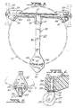
- FIG. 1 illustrates tank 12 of vacuum cleaner 11 mounted on dolly 10 which is constructed in accordance with teachings of the instant invention.
- tank 12 is provided with cylindrical side wall 14.
- the lower end of tank 12 is closed by recessed disc 17, having a reversely curled peripheral edge that constitutes bead 18 which surrounds side wall 14 at the bottom edge thereof.
- Dolly 10 includes generally T-shaped base 20 formed through the cooperation of crossarm 21 and leg 22. The latter extends from the center of crossarm 21 and at right angles thereto.
- Both elements 21 and 22 are constructed of a relatively hard, rugged plastic such as foamed high density polyethylene.
- Metal rod 23 extends longitudinally through crossarm 21 and constitutes a fixed axle for relatively large wheels 24, 24 that are mounted to opposite ends of rod 23 just outboard of the enlarged ends of crossarm 21, with push-type cap nuts 26, 26 retaining wheels 24, 24 mounted on axle 23.
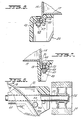
- Swivel-type wheel unit 27 is mounted to leg 22 at the enlarged end thereof disposed remote from crossarm 21.
- Wheel unit 27 includes wheel 28 rotatably mounted on horizontal pin 29 that extends between the arms of U-shaped bracket 31.
- Stem 32 constituting a swivel axis for unit 27, extends upward from the web of bracket 31 into plastic insert 33. The latter is disposed within recess or well 34 in the bottom of leg 22, being captured by the head of screw 36 (Fig. 4) that is threaded into leg recess 37 (Fig. 9).
- leg 22 is of T-shaped cross-section, as indicated by hatched section 38 in Fig. 11.
- this T cross-section 38 extends to the end of leg 22 that is remote from wheel 28.
- the upper surface of leg 22 at the enlarged end thereof where wheel 28 is mounted is provided with transverse arcuate groove 41 that receives bead 18 at the lower edge of tank 12.
- transverse arcuate groove 41 that receives bead 18 at the lower edge of tank 12.
- two apertures 42 Spaced with respect to the length of groove 41 and disposed immediately to the outboard side thereof are two apertures 42, each of which receives a hex-head screw 43 (Fig. 6) entered through the top of hole 42.
- Screw head 44 is disposed within recess 46 which is shaped to prevent rotation of screw 43. A portion of head 44 engages bead 18 along the upper edge thereof to capture the latter within groove 41. Screw 43 is held in position by nut 47 that is threadedly mounted thereon at the rear of leg 22, with washer 48 being interposed between nut 47 and a bottom surface of leg 22. In a similar manner, tank 12 is secured to opposite enlarged ends of crossarm 21.
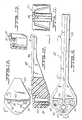
- the upper surface of crossarm 21 at each enlarged end thereof is provided with an arcuate groove 51 that is open at the top for the length thereof.
- Through aperture 52 is formed along the outboard edge of groove 51 to receive an additional holding screw 43.
- Head 44 of each additional screw 43 is received within a partially hexagonal depression 56 and overlies bead 18 to block the latter from leaving groove 51.
- Short transverse projection 61, at the center of base member 21, is provided with T-shaped depression 62 that complements T-shaped portion 38 of leg 22 (Fig. 13). The latter at its free end is entered into complementary 62 so as to permit base members 21 and 22 to slide relative to one another in a manner such that there is limited adjustment therebetween, as indicated by arrow A in Fig. 2.
- This adjustment enables dolly 10 to be fastened readily and securely to tanks 12 that fall within an acceptable relatively wide range of dimensional variation.
- Crossarm 21 also includes longitudinal passage 65 which is open at the top thereof for the major portion of its length. This top opening to passage 65 extends from one groove 51 to the other groove 51. Each end portion of passage 65 outboard of grooves 51 is open at the bottom thereof. In this way axle rod 23 that extends through passage 65 is retained against transverse movement by crossarm 21.
- the lower portions of grooves 51 communicate with passage 65 so that bead 18 at the lower edge of drum 12 rests directly against rod 23. This direct contact between axle 23 and the lower edge of bead 18 serves to protect the plastic elements of dolly 10 from severe impacts such as those occurring when descending stairs.
- Depression 62 communicates with passage 65 at the center thereof and permits T-shaped portion 38 of leg 22 to extend over axle rod 23.
- Dolly 10 is mounted to tank 12 by locating leg 22 so that swivel unit 27 is under inlet 99 and then tightening nuts 47 on two screws 43 carried by leg 22. Thereafter, crossarm 21 is positioned by mating same with the end of leg 22 remote from wheel 28 and then securing the latter to drum 12 by tightening nuts 47 on the other two screws 43.
- the upper surface 98 of leg 22 is adjacent the recessed bottom surface provided by disc 17, and the end of leg 22 remote from wheel unit 27 is captured between drum closure disc 17 and crossarm 21.
Landscapes
- Engineering & Computer Science (AREA)
- Chemical & Material Sciences (AREA)
- Combustion & Propulsion (AREA)
- Transportation (AREA)
- Mechanical Engineering (AREA)
- Handcart (AREA)
Abstract
Description
- This invention relates to dollies in general, and more particularly relates to the frame of a dolly that is secured to the bottom of a barrel or tank which is standing on end.
- There are many mobile devices that include barrels or tanks positioned standing on end. Typical of such devices are so-called bypass type vacuum cleaners where a suction-producing fan means is removably mounted to the top of a tank wherein dirt, including liquid, is collected. These tanks are mounted on dollies that are usually provided with means for securing the tanks to the dollies.
- Many prior art dollies of this type include a base that is constructed of relatively expensive elements or there are many elements that are costly to assembly, and there is very little flexibility insofar as being able to use a particular dolly for many tanks that fall within a reasonably large acceptable range of dimensional variation. An example of a prior art dolly of this type is found in United States Patent No. 4,650,200 issued March 17, 1987 in the name of R.C. Berfield, R.L. Crevling, Jr. and D.G. Rightnour, and titled DOLLY WITH TANK HOLDING DEVICE. The dolly of U.S. Patent No. 4,650,200 is provided with a frame constructed of formed and stamped metal elements to which separate brackets for mounting swivel-type wheel units are secured.
- In accordance with the instant invention, a dolly is constructed with a base consisting of two elongated plastic elements that are interengaged in a T-configuration, with one element constituting the crossarm and the other element constituting a leg which extends from the center of the crossarm and at right angles thereto. The connection between the leg and crossarm permits limited adjustment between these elements so that the drum diameter need not have a close tolerance. A metal rod constituting an axle extends lengthwise through the crossarm and mounts wheels at opposite ends thereof. At the end of the leg remote from the crossarm there is a well that receives the stem of a swivel-type wheel unit. The front or top of the base is provided with three slots, two being at opposite enlarged ends of the crossarm and the third being at the enlarged end of the leg remote from the crossarm. These slots receive the peripheral bead at the bottom of the drum, which bead is held in the slots by screws that are mounted to the base, with portions of the screw heads overlapping the bead.
- Accordingly, the primary object of the instant invention is to provide an inexpensive dolly that is readily securable to a drum which is standing on end.
- Another object is to provide a dolly of this type that includes a load carrying base constructed of interengaging plastic elements.
- Still another object is to provide a dolly of this type in which there is a wheel axle that extends longitudinally through one of the plastic elements and is disposed for direct support of the drum.
- A further object is to provide a dolly of this type in which the base is provided with an integrally formed well that receives the stem of a swivel-type wheel unit.
- A still further object is to provide a dolly of this type that is adjustable for use with drums of different diameters that fall within a reasonably large range of dimensional variation.
- The foregoing objects, as well as other objects of this invention will become readily apparent reading the following description of the accompanying drawings in which:
- Fig. 1 is a perspective of a vacuum cleaner mounted on a dolly constructed in accordance with teachings of the instant invention;
- Fig. 2 is a perspective of the dolly of Fig. 1;
- Fig. 3 is a top or front view of the dolly base;
- Fig. 4 is a fragmentary cross-section illustrating a swivel-type wheel unit mounted to the base;
- Fig. 5 is a fragmentary rear or back view of the base in Fig. 4;
- Fig. 6 is a fragmentary top view illustrating securement of the drum to the base at one enlarged end of the base crossarm;
- Fig. 7 is a partial cross-section illustrating securement of the vacuum cleaner drum to one enlarged end of the crossarm base;
- Fig. 8 is a partial cross-section illustrating securement of the vacuum cleaner drum to the enlarged end of the base leg;
- Fig. 9 is a rear elevation of the base leg;
- Fig. 10 is a fragmentary portion of the base leg taken through section line 10-10 of Fig. 9, looking in the direction of arrows 10-10;
- Fig. 11 is an elevation of the base leg, looking in the direction of arrows 11-11 of Fig. 10 toward the cutaway end of the base leg;
- Fig. 12 is a front elevation of the base leg end remote from the base crossarm;
- Fig. 13 is a partial section taken through line 13-13 of Fig. 12, looking in the direction of arrows 13-13;
- Fig. 14 is a top plan or front view of the crossarm;
- Fig. 15 is a partial longitudinal section of the crossarm taken through line 15-15 of Fig. 14, looking in the direction of arrows 15-15;
- Fig. 16 is an end view of the crossarm, looking in the direction of arrows 16-16 of Fig. 15;
- Figs. 17 and 18 are partial cross-sections of the crossarm taken through the respective lines 17-17 and 18-18 of Fig. 14, looking in the direction of the respective arrows 17-17 and 18-18;
- Fig. 19 is a bottom or rear view of one end of the crossarm;
- Figs. 20 and 21 are cross-sections taken through the respective lines 20-20 and 21-21 of Fig. 19, looking in the directions of respective arrows 20-20 and 21-21;
- Fig. 22 is a fragmentary elevation of the crossarm looking in the direction of arrows 22-22 of Fig. 19.
- Now referring to the drawings, in which Fig. 1 illustrates
tank 12 ofvacuum cleaner 11 mounted ondolly 10 which is constructed in accordance with teachings of the instant invention. In a manner known to the art,tank 12 is provided withcylindrical side wall 14. Motor-blower assembly 15, removably held in operative position by a plurality of manuallyoperable latches 16, normally closes the upper end of thetank 12. The lower end oftank 12 is closed byrecessed disc 17, having a reversely curled peripheral edge that constitutesbead 18 which surroundsside wall 14 at the bottom edge thereof. Dolly 10 includes generally T-shaped base 20 formed through the cooperation ofcrossarm 21 andleg 22. The latter extends from the center ofcrossarm 21 and at right angles thereto. Bothelements -
Metal rod 23 extends longitudinally throughcrossarm 21 and constitutes a fixed axle for relativelylarge wheels rod 23 just outboard of the enlarged ends ofcrossarm 21, with push-type cap nuts retaining wheels axle 23. Swivel-type wheel unit 27 is mounted toleg 22 at the enlarged end thereof disposed remote fromcrossarm 21.Wheel unit 27 includeswheel 28 rotatably mounted onhorizontal pin 29 that extends between the arms of U-shapedbracket 31.Stem 32, constituting a swivel axis forunit 27, extends upward from the web ofbracket 31 intoplastic insert 33. The latter is disposed within recess or well 34 in the bottom ofleg 22, being captured by the head of screw 36 (Fig. 4) that is threaded into leg recess 37 (Fig. 9). - With particular reference to Figs. 9-13, it is seen that a major portion of
leg 22 is of T-shaped cross-section, as indicated by hatchedsection 38 in Fig. 11. For a reason which will hereinafter be explained, thisT cross-section 38 extends to the end ofleg 22 that is remote fromwheel 28. The upper surface ofleg 22 at the enlarged end thereof wherewheel 28 is mounted, is provided with transversearcuate groove 41 that receivesbead 18 at the lower edge oftank 12. Spaced with respect to the length ofgroove 41 and disposed immediately to the outboard side thereof are twoapertures 42, each of which receives a hex-head screw 43 (Fig. 6) entered through the top ofhole 42.Screw head 44 is disposed withinrecess 46 which is shaped to prevent rotation ofscrew 43. A portion ofhead 44 engagesbead 18 along the upper edge thereof to capture the latter withingroove 41.Screw 43 is held in position bynut 47 that is threadedly mounted thereon at the rear ofleg 22, withwasher 48 being interposed betweennut 47 and a bottom surface ofleg 22. In a similar manner,tank 12 is secured to opposite enlarged ends ofcrossarm 21. - That is, the upper surface of
crossarm 21 at each enlarged end thereof is provided with anarcuate groove 51 that is open at the top for the length thereof. Throughaperture 52 is formed along the outboard edge ofgroove 51 to receive an additional holdingscrew 43.Head 44 of eachadditional screw 43 is received within a partiallyhexagonal depression 56 and overliesbead 18 to block the latter from leavinggroove 51. Shorttransverse projection 61, at the center ofbase member 21, is provided with T-shapeddepression 62 that complements T-shapedportion 38 of leg 22 (Fig. 13). The latter at its free end is entered into complementary 62 so as to permitbase members dolly 10 to be fastened readily and securely totanks 12 that fall within an acceptable relatively wide range of dimensional variation. -
Crossarm 21 also includeslongitudinal passage 65 which is open at the top thereof for the major portion of its length. This top opening topassage 65 extends from onegroove 51 to theother groove 51. Each end portion ofpassage 65 outboard ofgrooves 51 is open at the bottom thereof. In thisway axle rod 23 that extends throughpassage 65 is retained against transverse movement bycrossarm 21. The lower portions ofgrooves 51 communicate withpassage 65 so thatbead 18 at the lower edge ofdrum 12 rests directly againstrod 23. This direct contact betweenaxle 23 and the lower edge ofbead 18 serves to protect the plastic elements ofdolly 10 from severe impacts such as those occurring when descending stairs.Depression 62 communicates withpassage 65 at the center thereof and permits T-shapedportion 38 ofleg 22 to extend overaxle rod 23. -
Dolly 10 is mounted totank 12 by locatingleg 22 so thatswivel unit 27 is under inlet 99 and then tighteningnuts 47 on twoscrews 43 carried byleg 22. Thereafter, crossarm 21 is positioned by mating same with the end ofleg 22 remote fromwheel 28 and then securing the latter to drum 12 by tighteningnuts 47 on the other twoscrews 43. Theupper surface 98 ofleg 22 is adjacent the recessed bottom surface provided bydisc 17, and the end ofleg 22 remote fromwheel unit 27 is captured betweendrum closure disc 17 andcrossarm 21. - Although the present invention has been described in connection with a preferred embodiment thereof, many variations and modifications will now become apparent to those skilled in the art. It is preferred, therefore, that the present invention be limited not by the specific disclosure herein, but only by the appended claims.
Claims (20)
a base, wheel means on said base for positioning the latter so that it is generally horizontal, and fastening means for maintaining a tank, supported by said base from below, secured to said base;
said base being constructed of synthetic elements connected in a generally T-shaped configuration.
Applications Claiming Priority (2)
| Application Number | Priority Date | Filing Date | Title |
|---|---|---|---|
| US07/047,202 US4799699A (en) | 1987-05-06 | 1987-05-06 | Dolly frame |
| US47202 | 1987-05-06 |
Publications (3)
| Publication Number | Publication Date |
|---|---|
| EP0289937A2 true EP0289937A2 (en) | 1988-11-09 |
| EP0289937A3 EP0289937A3 (en) | 1988-12-28 |
| EP0289937B1 EP0289937B1 (en) | 1991-03-27 |
Family
ID=21947626
Family Applications (1)
| Application Number | Title | Priority Date | Filing Date |
|---|---|---|---|
| EP88106799A Expired EP0289937B1 (en) | 1987-05-06 | 1988-04-28 | Dolly frame |
Country Status (5)
| Country | Link |
|---|---|
| US (1) | US4799699A (en) |
| EP (1) | EP0289937B1 (en) |
| AU (1) | AU610881B2 (en) |
| CA (1) | CA1306481C (en) |
| DE (1) | DE3862146D1 (en) |
Cited By (4)
| Publication number | Priority date | Publication date | Assignee | Title |
|---|---|---|---|---|
| US5088751A (en) * | 1990-05-07 | 1992-02-18 | Zint Jerry A | Garden cart |
| EP1520502A3 (en) * | 2003-10-02 | 2006-03-29 | Shop Vac Corporation | Caster and dolly wheel attachments for cylindrical tank-type vacuum cleaners |
| FR2934988A1 (en) * | 2008-08-14 | 2010-02-19 | Denis Papin Collectivites | Furniture i.e. cabinet, displacing device for use in e.g. office, has fixation units offset horizontally above lifting surface so as to slightly raise surface with respect to floor, where surface supports furniture |
| EP2543299A3 (en) * | 2011-07-07 | 2016-12-28 | Shop VAC Corporation | Portable cleaner with axle mount |
Families Citing this family (18)
| Publication number | Priority date | Publication date | Assignee | Title |
|---|---|---|---|---|
| CA2113965C (en) * | 1993-08-04 | 1997-03-04 | William J. Rakocy | Tip resistant canister for upright vacuum cleaners |
| USD365178S (en) | 1993-08-04 | 1995-12-12 | Gmi Holdings, Inc. | Canister exterior for a wet/dry vacuum |
| USD360718S (en) | 1993-08-04 | 1995-07-25 | Gmi Holdings, Inc. | Power head for a wet/dry vacuum |
| US5440780A (en) * | 1993-08-04 | 1995-08-15 | Gmi Holdings, Inc. | Tip-resistant canister for upright vacuum cleaners |
| US5433463A (en) * | 1994-06-13 | 1995-07-18 | Finley; Rocky | Bucketeer on wheels |
| USD362326S (en) | 1994-09-26 | 1995-09-12 | Stout George E | Waste container dolly |
| US5816591A (en) * | 1996-01-30 | 1998-10-06 | Cascade Engineering, Inc. | Refuse container |
| US6170118B1 (en) | 1997-10-15 | 2001-01-09 | Upkeeper Corporation | Collection apparatus for use with blower/vacuum units |
| US6237187B1 (en) * | 1998-08-31 | 2001-05-29 | Emerson Electric Co. | Wet/dry vacuum dolly |
| US7494137B2 (en) * | 2006-02-17 | 2009-02-24 | Doak Bernard A | Snow plow dolly |
| US8042215B2 (en) * | 2008-06-09 | 2011-10-25 | Thibault Richard R | Cleaning system for removing abrading material |
| GB201213203D0 (en) * | 2012-07-25 | 2012-09-05 | Linde Ag | Wheels for pressure vessel |
| US9150234B2 (en) * | 2013-03-15 | 2015-10-06 | San Jamar, Inc. | Tote transport |
| US9192270B2 (en) | 2013-09-12 | 2015-11-24 | Shop Vac Corporation | Drain system and method for vacuum cleaner |
| US10377401B2 (en) | 2016-05-12 | 2019-08-13 | Richard Thibault | Interchangeable and modular carts |
| US10273082B2 (en) * | 2017-06-30 | 2019-04-30 | Peter Alden LOUNSBURY | Attachable stabilizer for laterally supporting a garbage bin |
| US10286943B1 (en) * | 2018-04-26 | 2019-05-14 | Marlin Steel Wire Products LLC | Material handling device |
| US11974714B2 (en) | 2022-03-24 | 2024-05-07 | Gregory M. Selinger | Wet/dry vacuum stand and bottom discharge |
Family Cites Families (11)
| Publication number | Priority date | Publication date | Assignee | Title |
|---|---|---|---|---|
| US2772889A (en) * | 1955-03-10 | 1956-12-04 | Scott E Reynolds | Wheeled support for containers |
| US2818271A (en) * | 1956-07-05 | 1957-12-31 | Saeli Anthony | Carrier for garbage cans and the like |
| US3463505A (en) * | 1967-12-20 | 1969-08-26 | Israel Robert German | Combined container and detachably mounted roller assembly |
| US3734527A (en) * | 1971-02-04 | 1973-05-22 | Beatrice Foods Co | Bucket chassis |
| US3837666A (en) * | 1973-02-16 | 1974-09-24 | B Hodson | Container wheel attachment |
| DE2749905A1 (en) * | 1977-11-08 | 1979-05-10 | Ernst Pahl | Wheeled support frame for dustbin - includes sprung frame to grip under bin and fitted with fixed castors |
| AU4470579A (en) * | 1978-03-02 | 1979-09-06 | Ronald Edward Sim | Collapsible carrier |
| GB1584489A (en) * | 1978-05-31 | 1981-02-11 | Groves J V G | Container supports |
| AU539202B2 (en) * | 1980-05-21 | 1984-09-13 | Leary, William | Lifting device |
| US4572531A (en) * | 1984-06-15 | 1986-02-25 | Elia Thomas L | Snow plow dolly |
| FR2584989B1 (en) * | 1985-07-17 | 1990-05-18 | Djouad Mohamed | DEVICE FOR ATTACHING SOLIDARITY TO A CONTAINER TO FACILITATE MOVEMENT |
-
1987
- 1987-05-06 US US07/047,202 patent/US4799699A/en not_active Ceased
-
1988
- 1988-04-28 DE DE8888106799T patent/DE3862146D1/en not_active Expired - Fee Related
- 1988-04-28 EP EP88106799A patent/EP0289937B1/en not_active Expired
- 1988-05-04 AU AU15578/88A patent/AU610881B2/en not_active Ceased
- 1988-05-05 CA CA000566020A patent/CA1306481C/en not_active Expired - Lifetime
Cited By (7)
| Publication number | Priority date | Publication date | Assignee | Title |
|---|---|---|---|---|
| US5088751A (en) * | 1990-05-07 | 1992-02-18 | Zint Jerry A | Garden cart |
| EP1520502A3 (en) * | 2003-10-02 | 2006-03-29 | Shop Vac Corporation | Caster and dolly wheel attachments for cylindrical tank-type vacuum cleaners |
| US7165290B2 (en) | 2003-10-02 | 2007-01-23 | Shop-Vac Corporation | Caster and dolly wheel attachments for cylindrical tanks |
| EP1955633A2 (en) | 2003-10-02 | 2008-08-13 | Shop Vac Corporation | Caster and dolly wheel attachments for cylindrical tank-type vacuum cleaners |
| EP1955633A3 (en) * | 2003-10-02 | 2008-08-20 | Shop Vac Corporation | Caster and dolly wheel attachments for cylindrical tank-type vacuum cleaners |
| FR2934988A1 (en) * | 2008-08-14 | 2010-02-19 | Denis Papin Collectivites | Furniture i.e. cabinet, displacing device for use in e.g. office, has fixation units offset horizontally above lifting surface so as to slightly raise surface with respect to floor, where surface supports furniture |
| EP2543299A3 (en) * | 2011-07-07 | 2016-12-28 | Shop VAC Corporation | Portable cleaner with axle mount |
Also Published As
| Publication number | Publication date |
|---|---|
| EP0289937B1 (en) | 1991-03-27 |
| AU610881B2 (en) | 1991-05-30 |
| AU1557888A (en) | 1988-11-10 |
| US4799699A (en) | 1989-01-24 |
| CA1306481C (en) | 1992-08-18 |
| DE3862146D1 (en) | 1991-05-02 |
| EP0289937A3 (en) | 1988-12-28 |
Similar Documents
| Publication | Publication Date | Title |
|---|---|---|
| EP0289937A2 (en) | Dolly frame | |
| US7222763B2 (en) | Pivoting support arrangement for maintaining a bicycle wheel in an upright position | |
| US6010187A (en) | Chair for a mechanic | |
| US5443189A (en) | Article mounting assembly for a vehicle mounted carrier | |
| US4099760A (en) | Grill and brush guard and utility rack for a vehicle | |
| US5065921A (en) | Bicycle rack for mounting on a van | |
| US7758055B2 (en) | Dolly with wheel lock | |
| US6367494B1 (en) | Movable sunshade base | |
| US4804070A (en) | Lockable vehicle wheel chock device | |
| US6331094B1 (en) | Wheel chock for use in transporting a cycle on a vehicle | |
| US5730343A (en) | Tower assembly for mounting a crossbar to a vehicle roof rack | |
| US4679717A (en) | Spare tire carrier | |
| US5815976A (en) | Fishing rod holder securable to the bumper of a vehicle | |
| US4410116A (en) | Adjustable-drop package carrier rack for two-wheel vehicles such as bicycles | |
| US5259720A (en) | Rotary and tilt snowmobile trailer apparatus | |
| USRE34130E (en) | Dolly frame | |
| US4111344A (en) | Spare tire and wheel securing device | |
| US20040182663A1 (en) | Collapsible bar assembly for supporting a secondary bag on wheeled luggage | |
| US5678973A (en) | Vehicle seat transporter cart | |
| US5641108A (en) | Bicycle and ski carrier for attachment to an automobile receiver hitch | |
| US20020180180A1 (en) | Trailer hitch with trailer hitch accessory mounting assembly | |
| US6039521A (en) | Truck bed enclosure attachment posts | |
| US5836491A (en) | Lock securing device for a bicycle | |
| US4161267A (en) | Trunk mount spare wheel carrier device | |
| US20050212234A1 (en) | Shopping cart extender |
Legal Events
| Date | Code | Title | Description |
|---|---|---|---|
| PUAI | Public reference made under article 153(3) epc to a published international application that has entered the european phase |
Free format text: ORIGINAL CODE: 0009012 |
|
| PUAL | Search report despatched |
Free format text: ORIGINAL CODE: 0009013 |
|
| AK | Designated contracting states |
Kind code of ref document: A2 Designated state(s): CH DE FR GB LI |
|
| AK | Designated contracting states |
Kind code of ref document: A3 Designated state(s): CH DE FR GB LI |
|
| 17P | Request for examination filed |
Effective date: 19881117 |
|
| 17Q | First examination report despatched |
Effective date: 19900301 |
|
| GRAA | (expected) grant |
Free format text: ORIGINAL CODE: 0009210 |
|
| AK | Designated contracting states |
Kind code of ref document: B1 Designated state(s): CH DE FR GB LI |
|
| REF | Corresponds to: |
Ref document number: 3862146 Country of ref document: DE Date of ref document: 19910502 |
|
| ET | Fr: translation filed | ||
| PLBE | No opposition filed within time limit |
Free format text: ORIGINAL CODE: 0009261 |
|
| STAA | Information on the status of an ep patent application or granted ep patent |
Free format text: STATUS: NO OPPOSITION FILED WITHIN TIME LIMIT |
|
| 26N | No opposition filed | ||
| PGFP | Annual fee paid to national office [announced via postgrant information from national office to epo] |
Ref country code: FR Payment date: 19940411 Year of fee payment: 7 |
|
| PGFP | Annual fee paid to national office [announced via postgrant information from national office to epo] |
Ref country code: GB Payment date: 19940419 Year of fee payment: 7 |
|
| PGFP | Annual fee paid to national office [announced via postgrant information from national office to epo] |
Ref country code: CH Payment date: 19940425 Year of fee payment: 7 |
|
| PGFP | Annual fee paid to national office [announced via postgrant information from national office to epo] |
Ref country code: DE Payment date: 19940426 Year of fee payment: 7 |
|
| PG25 | Lapsed in a contracting state [announced via postgrant information from national office to epo] |
Ref country code: GB Effective date: 19950428 |
|
| PG25 | Lapsed in a contracting state [announced via postgrant information from national office to epo] |
Ref country code: LI Effective date: 19950430 Ref country code: CH Effective date: 19950430 |
|
| REG | Reference to a national code |
Ref country code: CH Ref legal event code: PL |
|
| PG25 | Lapsed in a contracting state [announced via postgrant information from national office to epo] |
Ref country code: FR Effective date: 19951229 |
|
| GBPC | Gb: european patent ceased through non-payment of renewal fee |
Effective date: 19950428 |
|
| PG25 | Lapsed in a contracting state [announced via postgrant information from national office to epo] |
Ref country code: DE Effective date: 19960103 |
|
| REG | Reference to a national code |
Ref country code: FR Ref legal event code: ST |