EP0288811A2 - Improved interlock switch baseplate - Google Patents
Improved interlock switch baseplate Download PDFInfo
- Publication number
- EP0288811A2 EP0288811A2 EP88105746A EP88105746A EP0288811A2 EP 0288811 A2 EP0288811 A2 EP 0288811A2 EP 88105746 A EP88105746 A EP 88105746A EP 88105746 A EP88105746 A EP 88105746A EP 0288811 A2 EP0288811 A2 EP 0288811A2
- Authority
- EP
- European Patent Office
- Prior art keywords
- actuator
- switch
- operator
- baseplate
- motion
- Prior art date
- Legal status (The legal status is an assumption and is not a legal conclusion. Google has not performed a legal analysis and makes no representation as to the accuracy of the status listed.)
- Withdrawn
Links
- 230000000717 retained effect Effects 0.000 claims abstract description 6
- 230000006872 improvement Effects 0.000 claims description 4
- 230000000903 blocking effect Effects 0.000 claims description 3
- 230000014759 maintenance of location Effects 0.000 claims 2
- 230000004044 response Effects 0.000 abstract description 3
- 238000010411 cooking Methods 0.000 abstract description 2
- 230000000712 assembly Effects 0.000 description 3
- 238000000429 assembly Methods 0.000 description 3
- 230000009471 action Effects 0.000 description 2
- 239000002131 composite material Substances 0.000 description 1
- 230000013011 mating Effects 0.000 description 1
- 239000002184 metal Substances 0.000 description 1
- 230000004048 modification Effects 0.000 description 1
- 238000012986 modification Methods 0.000 description 1
Images


Classifications
-
- H—ELECTRICITY
- H01—ELECTRIC ELEMENTS
- H01H—ELECTRIC SWITCHES; RELAYS; SELECTORS; EMERGENCY PROTECTIVE DEVICES
- H01H3/00—Mechanisms for operating contacts
- H01H3/02—Operating parts, i.e. for operating driving mechanism by a mechanical force external to the switch
- H01H3/16—Operating parts, i.e. for operating driving mechanism by a mechanical force external to the switch adapted for actuation at a limit or other predetermined position in the path of a body, the relative movement of switch and body being primarily for a purpose other than the actuation of the switch, e.g. for a door switch, a limit switch, a floor-levelling switch of a lift
-
- H—ELECTRICITY
- H05—ELECTRIC TECHNIQUES NOT OTHERWISE PROVIDED FOR
- H05B—ELECTRIC HEATING; ELECTRIC LIGHT SOURCES NOT OTHERWISE PROVIDED FOR; CIRCUIT ARRANGEMENTS FOR ELECTRIC LIGHT SOURCES, IN GENERAL
- H05B6/00—Heating by electric, magnetic or electromagnetic fields
- H05B6/64—Heating using microwaves
- H05B6/6414—Aspects relating to the door of the microwave heating apparatus
- H05B6/6417—Door interlocks of the microwave heating apparatus and related circuits
-
- H—ELECTRICITY
- H01—ELECTRIC ELEMENTS
- H01H—ELECTRIC SWITCHES; RELAYS; SELECTORS; EMERGENCY PROTECTIVE DEVICES
- H01H3/00—Mechanisms for operating contacts
- H01H3/02—Operating parts, i.e. for operating driving mechanism by a mechanical force external to the switch
- H01H3/16—Operating parts, i.e. for operating driving mechanism by a mechanical force external to the switch adapted for actuation at a limit or other predetermined position in the path of a body, the relative movement of switch and body being primarily for a purpose other than the actuation of the switch, e.g. for a door switch, a limit switch, a floor-levelling switch of a lift
- H01H3/161—Operating parts, i.e. for operating driving mechanism by a mechanical force external to the switch adapted for actuation at a limit or other predetermined position in the path of a body, the relative movement of switch and body being primarily for a purpose other than the actuation of the switch, e.g. for a door switch, a limit switch, a floor-levelling switch of a lift for actuation by moving a closing member, e.g. door, cover or lid
- H01H3/163—Operating parts, i.e. for operating driving mechanism by a mechanical force external to the switch adapted for actuation at a limit or other predetermined position in the path of a body, the relative movement of switch and body being primarily for a purpose other than the actuation of the switch, e.g. for a door switch, a limit switch, a floor-levelling switch of a lift for actuation by moving a closing member, e.g. door, cover or lid associated with locking or manipulating means of the closing member
-
- Y—GENERAL TAGGING OF NEW TECHNOLOGICAL DEVELOPMENTS; GENERAL TAGGING OF CROSS-SECTIONAL TECHNOLOGIES SPANNING OVER SEVERAL SECTIONS OF THE IPC; TECHNICAL SUBJECTS COVERED BY FORMER USPC CROSS-REFERENCE ART COLLECTIONS [XRACs] AND DIGESTS
- Y10—TECHNICAL SUBJECTS COVERED BY FORMER USPC
- Y10S—TECHNICAL SUBJECTS COVERED BY FORMER USPC CROSS-REFERENCE ART COLLECTIONS [XRACs] AND DIGESTS
- Y10S292/00—Closure fasteners
- Y10S292/69—Washing machine or stove closure latch
Abstract
An interlock switch assembly (10) is disclosed having a unitary baseplate (12) with relatively few moving parts and making use of conventional low cost miniature switches, each positively located and retained with respect to the baseplate (12). First and second actuators (34, 36) convert, respectively, linear motion of first and second operators (19, 20) into rotary motion to actuate the miniature switches (26a, 26b). Switch actuation is prevented unless the properly timed motion of both operators (19, 20) is received by the actuators (34, 36). A third actuator (100) receives the motion of the first operator (19) and actuates a third switch (30) in response thereto. In one embodiment, the third actuator (100) is prevented from actuating the third switch (30) until after actuation of the first and second switches (26a, 26b). In one embodiment, a primary interlock switch (30) is the first switch deactuated and is preferably capable of interrupting power to the microwave energy source when the door is opened before the cooking cycle is completed. In this embodiment, the next switch to be deactuated is a logic monitor switch (26a), followed by release of a secondary interlock switch (26b) acting as a backup to the primary interlock switch (30). Finally, an interlock monitor switch (32) is deactuated preferably placing a short circuit across the load side of a power circuit of the switch assembly (10) in order to blow a fuse in the event of a "failed-closed" condition of both the primary and secondary interlock switches (26a, 26b) in the deactuated state.
Description
- In the past, designs of interlock switch assemblies for microwave ovens have progressed from relatively complex assemblies made up of a number of switches individually mounted in sheet metal bracket assemblies requiring individual switch adjustment to custom interlock switch modules containing a plurality of specially designed switches positively positioned within a unitary housing. Such custom interlock switch modules reduced the number of adjustments but required relatively costly tooling because of the need for completely redesigned switch elements.
- In switch designs overcoming the need for custom designed switch elements such as that shown in U.S. Patent application serial no. 866,115 - now U.S. Patent No. 4663 505 - filed May 22, 1986, by George Michael Drake, it has been found desirable to provide still further improvements to further prevent actuation except in response to door closing.
- The present invention provides for an improvement in a unitary switch module by providing an additional actuator which is designed to receive door operator motion to actuate an interlock switch. The actuator is designed to be tamper-proof in that it is relatively inaccessible even through the door operator apertures in the front wall of the unitary switch module and is held in the deactuated state until the other actuators move to their respective enabling positions.
-
- FIG. 1 shows a side view of one embodiment of the interlock switch assembly in the deactuated state.
- FIG 1A show a detail view of the mounting arrangement for a pair of stacked switches taken along line 1A-1A of Fig. 1.
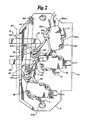
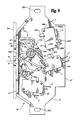
- FIG 2 shows a side view of the interlock switch assembly of FIG 1 in the actuated state.
- FIG 3 shows a side view of the interlock switch assembly of FIGS 1 and 2 in a state intermediate the actuated and deactuated states.
- FIG 4A shows a front view of the baseplate of FIG 1.
- FIG 4B shows a composite section and exploded view of a portion of the baseplate taken along
line 4B-4B of FIG 4C and the mounting arrangement of the actuators of FIG 1. - FIG 4C shows a side view of the baseplate and detail views of a spring-retaining projection on the baseplate of FIG 1.
- FIG 4D shows a partial section detail view taken along
line 4D-4D of FIG 4C of switch retaining fingers and locating post for a swtich to be mounted on the baseplate of FIG 1. - FIG 4E shows a partial section taken along
line 4E-4E of FIG 4C of fingers and a post for retaining and locating a plurality of switches to be mounted on the baseplate of FIG 1. - FIG 4F shows a partial section detail view taken along
line 4F-4F of FIG 4C of an actuator-retaining channel on the baseplate of FIG 1. - FIG 5A shows a front view of a first actuator.
- FIG 5B shows a side view of the first actuator.
- FIG 5C shows a partial section view of a spring retaining projection on the first actuator taken along
line 5C-5C of FIG 5B. - FIG 5D shows another partial section view through the first actuator taken along
line 5D-5D of FIG 5B. - FIG 5E shows a rear view of the first actuator.
- FIG 5F shows a section view through the first actuator taken along
line 5F-5F of FIG 5B. - FIG 5G shows a back view of the first actuator.
- FIG 5H shows a partial section view through a second actuator taken along line 5H-5H of FIG 5I.
- FIG 5I shows a side view of the second actuator.
- FIG 5J shows a rear view of the second actuator.
- FIG. 5K shows a top view of the second actuator.
- FIG. 6 shows a microwave oven partially cutaway to illustrate an interlock switch baseplate assembly of this invention installed in an oven.
- FIG. 7A shows a side view of the third actuator.
- FIG. 7B shows an end view of the third actuator.
- FIG. 7C shows a bottom view of the third actuator.
- FIG. 8A shows a partial view of the first and third actuators to illustrate the interengaging surfaces in the deactuated state.
- FIG. 8B shows a view of the actuators of FIG. 8A in the actuated state.
- FIG. 9 shows an alternative embodiment of the interlock switch assembly.
- Referring to FIG. 1, an
interlock switch assembly 10 is shown, having a unitary baseplate orframe 12.Frame 12 has a front wall orpanel 14 containing first andsecond apertures second operators axis A. Operators Operator 19 preferably has an enlargeddistal portion 23 and retains the door in a closed position while the switch assembly is actuated. In FIG. 1,switch assembly 10 is shown in the deactuated state which corresponds to a door-open state of the microwave oven with the operators withdrawn fromapertures Frame 12 also has a generally planar wall or mountingsurface 21 preferably at a right angle tofront wall 14. Surface orbase 21 haselongated apertures 22a,b adapted formounting assembly 10 to a microwave oven and for allowing adjustment only along a direction parallel toaxis A. Apertures 22a,b are preferably, but not necessarily, used in cooperation with bosses orstuds 33a,b which are to be received in mating slots in the mounting surface to whichbase 12 is secured. -
Surface 21 has a pair ofrectangular fingers miniature switches Switches assembly 10 at a pair ofcylindrical posts Fingers posts base 21. FIG 1A shows mounting details and the stacked arrangement ofswitches individual switches - Each of
switches preferred embodiment switch 26a has a normally-open contact and functions as alogic monitor switch 26b is a normally-open and functions as a secondary interlock,switch 30 is a normally-open and functions as primary interlock switch, andswitch 32 has a normally-closed contact and functions as an interlock monitor switch. - A
first actuator 34 receives and converts the motion ofoperator 19 from a linear motion into a rotary motion and sequentially actuates switches 26a and 26b. - A
second actuator 36 receives and translates the linear motion ofoperator 20 into a rotary motion to actuatesecond actuator switch 32.Actuators operators apertures - A
third actuator 100 receives a portion of the motion ofoperator 19 to operateswitch 30.Actuators surfaces switch 30 whileactuator 34 is in either a deactuated or intermediate position. Whenactuator 34 is in its actuated position,inner cam 102 provides aclearance region 118 which permits movement ofactuator 100.Clearance region 118 is obscured from view throughaperture 16 whenactuator 34 is in the actuated state. - As may be best seen in FIG. 2, once
operators assembly 10, all switches are actuated, and becauseoperator 19 is a hook-type operator which engages asurface 38 onactuator 34, hook-type operator 19 is restrained from withdrawal throughaperture 16 while the switches are in the actuated state. It is to be understood that FIG. 1 corresponds to an open door condition while FIG. 2 corresponds to a closed-door condition of a microwave oven. As may be seen in FIG. 6,door 96 hasoperators assembly 10 is located behind the front panel 94 (shown in phantom in FIG. 2) of the microwave oven.Phantom panel 94 corresponds a section view of front parallel 94 of FIG. 6. Although themicrowave oven 92,door 96,operators front panel 94 form no part of the interlock switch assembly per se, they are shown in the figures as an aid in understanding this invention. - As
actuator 34 moves between the deactuated state shown in FIG. 1 and the actuated state shown in FIG. 2, aspring 42 provides an over-center action to retainactuator 34 in either the actuated or the deactuated state. - In the event that an attempt is made to operate
assembly 10 by inserting a projection or operator intoaperture 16 without a corresponding operator being inserted intoaperture 18,actuator 34 progresses to position 44, shown in phantom in FIG. 1. At this point, surfaces 46, 48 onactuators actuator 34. - Alternatively, if an operator is inserted into
aperture 18 without a corresponding operator being inserted intoaperture 16,interengaging surfaces actuator 36. - During normal operation, as the oven door is closed,
operator 19 moves actuator 34 slightly so thatsurfaces projection 52 onactuator 36 is free to enter recess orclearance region 54 inactuator 34 as may be more clearly seen in FIGS 2 and 3. - FIG 3 shows
interlock switch assembly 10 in an intermediate position withinterengaging surfaces actuators - With
operators actuator 100 is prevented from actuatingswitch 30 by the interference between an inner cam orsurface 102 onactuator 34 andsurface 104 onactuator 100. Asoperators cam surface 102 rotates away to provideclearance 118 for movement ofthird actuator 100. At the same time (as may be seen more clearly in FIG. 8B)operator 19urges driving surface 106 onactuator 100 to move actuator 100 towards button B onswitch 30, actuatingswitch 30. - FIGS 4A-4F shows various details of
baseplate 12. More particularly, FIG. 4A shows a front view of the front wall orpanel 14 indicating the relative position ofapertures apertures frames interior surface 60 to assist in receivingoperators - FIG. 4B shows a partial section view of
frame 12 and further shows an exploded view of the partialassembly including actuators first shaft 62 andactuator 36 is received on asecond shaft 64.Actuators rings 66a, 66b (shown in FIG 1). Alternatively, other fastening means may be used which restrain axial movement of the actuators while permitting rotational movement. - Referring now more particularly to FIG. 4C, still further details of the
baseplate 12 may be seen. Aprojection 68 shown in top, front and side views is designed to receive and retain one end ofspring 42. Atrack 108 is adapted to retainactuator 100 onbaseplate 12 while permitting sliding movement ofactuator 100 with respect tobaseplate 12. - The mounting arrangement for the single height and double height stacked switches are shown respectively in FIGS 4D and 4E.
Rectangular fingers 74a, 74b andcylindrical post 78a are similar tofingers post 28a, except that they are shorter by the width W of one miniature switch 26.Fingers posts - FIG. 4F shows the detail of mounting
track 108 which is preferably formed integrally withplanar surface 21 offrame 12.Track 108 has parallel opposingsides edges actuator 100 in a sliding relationship tobaseplate 12. - Referring now more particularly to FIGS 5A-5J, the various details of
actuators -
Interengaging surface 50b may be seen in FIGS 5A, 5B and 5F. A cross-section of aspring retaining projection 80 onactuator 34 is shown in FIG 5C. FIG 5D showssurface 38 which is adapted to retain the hook ofoperator 19. - FIGS 5B and 5E shows first and second initial cam surfaces 82, 84 and a common
final cam surface 86. Firstinitial cam surface 82 engages and actuatesswitch 26b prior to second initial cam surface engaging andactuating switch 26a. Subsequently, commonfinal cam surface 86 maintains bothswitches - FIGS. 5B, 5F and 5G show views of the
inner cam surface 102 ofactuator 34. - FIG. 5G shows the details of the back of
actuator 34, includingclearance region 118 adjacentinner cam 102. - Referring now more particularly to FIGS. 5H-5I, the various views and details of
actuator 36 may be seen. FIG. 5H shows a cross-section throughprojection 52. FIGS. 5I, 5J and 5K show the details of interengaging surfaces 48 and 50a which prevent actuation of any switch unless bothoperators apertures actuators actuator 36 has aswitch contacting surface 90 which actuatesswitch 32 whenactuator 36 is driven to the actuated position byoperator 20. - Referring now more particularly to FIG. 6, interlock
switch assembly 10 is shown in amicrowave oven 92 having afront panel 94 and a pivotingmicrowave oven door 96, which carries first andsecond operators Assembly 10 is mounted inoven 92 such that first andsecond apertures front wall 14 ofassembly 10 are positioned to align with corresponding apertures in thefront panel 94 ofoven 92. - Referring now more particularly to FIGS. 7A, 7B and 7C, the
third actuator 100 may be seen.Actuator 100 has drivingsurface 106 and engagingsurface 104 on ahead portion 110.Head portion 110 is preferably formed integrally withguide portion 112.Guide portion 112 is retained intrack 108 ofbaseplate 12 for sliding movement therein to actuate and deactuate switch 30 in response to translational motion of thedistal portion 23 ofoperator 19.Guide portion 112 preferably hasbarbs 120 or other retaining means for retainingactuator 100 intrack 108. - Referring now more particularly to FIGS. 8A and 8B, the
third actuator 100 receives a portion of the motion ofoperator 19 to operateswitch 30.Actuators surfaces switch 30 whileactuator 34 is in either a deactuated or intermediate position. When actuator 34 is in its actuated position, a blockingsurface 103 moves away from its rest position and provides aclearance 118 permitting movement ofactuator 100. Asoperators surface 103 rotates sufficiently to permitthird actuator 100 to engage and actuateswitch 30. Asoperator 19 progresses to the closed door position, it urges drivingsurface 106 onactuator 100 to move actuator 100 towards button B onswitch 30, actuatingswitch 30. - The
switch assembly 10 deactuation sequence is as follows. When the microwave oven door starts to open,operators Actuator 100 releases button B onswitch 30, opening ordeactuating switch 30. In a preferred embodiment,switch 26a is the first switch deactuated, followed by deactuation ofswitches switch 26a whose button B is released by thesecond cam surface 84. Next,cam surface 82 releases button B on thesecondary interlock switch 26b, acting as a backup to switch 30. Finally,actuator 36 moves sufficiently far to release button B on theinterlock monitor switch 32, thus deactuatingswitch 32 which preferably places a short circuit across the load side of the power circuit ofswitch assembly 10 to blow a fuse in the event of a "failed-closed" condition of bothswitches - Referring now to FIG 9, an
alternative embodiment 10 of the interlock switch assembly may be seen. In this embodiment, switch 30 has been moved, andparts - The invention is not to be taken to be limited to all of the details thereof as modifications and variations thereof may be made without departing from the spirit or scope of the invention.
Claims (10)
1. An improved interlock switch baseplate assembly for use with microwave ovens comprising:
a) a unitary baseplate having:
i) a generally planar first surface with mounting means therein for adjustably mounting said baseplate to an adjacent surface;
ii) a generally planar second surface projecting substantially perpendicularly from said first surface and containing first and second operator apertures therein;
iii) a plurality of sets of switch location and retention means integrally formed as a part of said baseplate and projecting substantially perpendicularly from said first surface for positively locating and retaining first, second and third switches on said baseplate; and
iv) first and second shaft means integrally formed as a part of said baseplate and projecting substantially perpendicularly from said first surface;
b) a first actuator positioned on said first shaft means and adapted to receive translational motion of a first operator received through said first operator aperture such that the translational motion of said first operator is converted into rotary motion for sequentially actuating and deactuating said first switch;
c) a second actuator positioned on said second shaft means and adapted to receive translational motion of a second operator received through said second operator aperture actuator such that the translational motion of said second operator is converted into rotary motion for actuating and deactuating said second switch wherein said first and second actuators have interengaging surfaces which prevent actuation of said first and second switches upon receiving the translation motion of one of the first and second operators without receipt of motion of the other; and
d) a third actuator retained in sliding relationship with said baseplate and adapted to receive translational motion of said first operator such that the translational motion of said first operator drives said third actuator for sequentially actuating said third switch such that said third switch is actuated after actuation of both said first and second switches.
2. The improvement of claim 1 wherein said third switch is deactuated before deactuation of either of said first and second switches.
3. The improvement of claim 1 wherein said first and third actuators are further characterized by interengaging surfaces preventing actuation of said third switch until said first actuator has rotated beyond interengagement with said second actuator.
4. The assembly of claim 1 wherein said first actuator has a blocking surface which prevents movement of said third actuator while said first actuator is in intermediate and deactuated positions.
5. The assembly of claim 4 wherein said first actuator has a clearance region which permits movement of said third actuator while said first actuator is in an actuated position.
6. The assembly of claim 5 wherein the clearance region of said first actuator is obscured from view through said first operator aperture while said first actuator is in an actuated position.
7. The assembly of claim 1 wherein said third actuator is released to actuate said third switch as said first actuator moves between intermediate and actuated positions.
8. The assembly of claim 1 wherein said third actuator has a driving surface adapted to receive and transfer translational motion of said distal portion of said first operator to said third switch when said first actuator moves from said intermediate to said actuated positions.
9. An interlock switch baseplate assembly in combination with a microwave oven comprising:
a) a unitary baseplate having:
i) a generally planar first surface with mounting means therein for adjustably mounting said baseplate to an adjacent surface;
ii) a generally planar second surface projecting substantially perpendicularly from said first surface and containing first and second operator apertures therein;
iii) a plurality of sets of switch location and retention means integrally formed as a part of said baseplate and projecting substantially perpendicularly from said first surface for positively locating and retaining first, second and third switches on said baseplate; and
iv) first and second shaft means integrally formed as a part of said baseplate and projecting substantially perpendicularly from said first surface;
i) a generally planar first surface with mounting means therein for adjustably mounting said baseplate to an adjacent surface;
ii) a generally planar second surface projecting substantially perpendicularly from said first surface and containing first and second operator apertures therein;
iii) a plurality of sets of switch location and retention means integrally formed as a part of said baseplate and projecting substantially perpendicularly from said first surface for positively locating and retaining first, second and third switches on said baseplate; and
iv) first and second shaft means integrally formed as a part of said baseplate and projecting substantially perpendicularly from said first surface;
b) a first actuator positioned on said first shaft means and adapted to receive translational motion of a first operator received through said first operator aperture such that the translational motion of said first operator is converted into rotary motion for sequentially actuating and deactuating said first switch;
c) a second actuator positioned on said second shaft means and adapted to receive translational motion of a second operator received through said second operator aperture actuator such that the translational motion of said second operator is converted into rotary motion for actuating and deactuating said second switch from among said plurality of switches located and retained on said baseplate; wherein said first and second actuator have interengaging surfaces which prevent actuation of said first and second switches upon receiving the translational motion of one of the first and second operators without receipt of motion of the other;
d) a third actuator retained in sliding relationship with said baseplate and adapted to receive translational motion of said first operator such that the translational motion of said first operator drives said third actuator for sequentially actuating said third switch such that said third switch is actuated after actuation of both said first and second switches; and
e) said microwave oven having a pivoting microwave oven door having first and second operators projecting therefrom.
10. The combination of the interlock switch baseplate assembly and microwave oven of claim 9 wherein said first operator further comprises an enlarged distal portion.
Applications Claiming Priority (2)
| Application Number | Priority Date | Filing Date | Title |
|---|---|---|---|
| US43216 | 1987-04-27 | ||
| US07/043,216 US4745250A (en) | 1987-04-27 | 1987-04-27 | Interlock switch baseplate assembly |
Publications (2)
| Publication Number | Publication Date |
|---|---|
| EP0288811A2 true EP0288811A2 (en) | 1988-11-02 |
| EP0288811A3 EP0288811A3 (en) | 1989-10-18 |
Family
ID=21926088
Family Applications (1)
| Application Number | Title | Priority Date | Filing Date |
|---|---|---|---|
| EP88105746A Withdrawn EP0288811A3 (en) | 1987-04-27 | 1988-04-11 | Improved interlock switch baseplate |
Country Status (10)
| Country | Link |
|---|---|
| US (1) | US4745250A (en) |
| EP (1) | EP0288811A3 (en) |
| JP (1) | JPS63281393A (en) |
| KR (1) | KR970000108B1 (en) |
| CN (1) | CN88102377A (en) |
| AR (1) | AR246635A1 (en) |
| AU (1) | AU1519888A (en) |
| BR (1) | BR8802002A (en) |
| CA (1) | CA1295691C (en) |
| ZA (1) | ZA881005B (en) |
Cited By (2)
| Publication number | Priority date | Publication date | Assignee | Title |
|---|---|---|---|---|
| EP1469257A2 (en) * | 2003-03-19 | 2004-10-20 | Lg Electronics Inc. | Door assembly for microwave oven |
| EP3560288A4 (en) * | 2017-01-26 | 2019-12-18 | Samsung Electronics Co., Ltd. | Cooking apparatus |
Families Citing this family (31)
| Publication number | Priority date | Publication date | Assignee | Title |
|---|---|---|---|---|
| JP2512920Y2 (en) * | 1990-04-09 | 1996-10-02 | シャープ株式会社 | Safety switch mechanism of high frequency heating device |
| JP2510915Y2 (en) * | 1990-04-27 | 1996-09-18 | シャープ株式会社 | Safety switch mechanism of high frequency heating device |
| FR2672111B1 (en) * | 1991-01-25 | 1993-10-15 | Moulinex Sa | DEVICE FOR PLACING IN THE STANDBY OF THE START OF A MICROWAVE OVEN. |
| US5174618A (en) * | 1991-12-09 | 1992-12-29 | Maytag Corporation | Door latch assembly |
| US6109667A (en) * | 1995-10-10 | 2000-08-29 | Collins; Matthew J. | Over-center toggle latch with integral switch |
| US6203077B1 (en) | 1997-10-03 | 2001-03-20 | Southco, Inc. | Over-center toggle latch with integral safety switch |
| US6111331A (en) * | 1999-03-22 | 2000-08-29 | General Electric Company | Air switch assembly for an electric motor |
| JP3655135B2 (en) * | 1999-08-23 | 2005-06-02 | 株式会社東芝 | Switch device |
| DE10062458B4 (en) * | 2000-12-14 | 2004-06-17 | Whirlpool Corp., Benton Harbor | Locking device for a washing machine or washer-dryer |
| US6761381B2 (en) * | 2001-08-09 | 2004-07-13 | General Electric Company | Methods and apparatus for securing a dishwasher door |
| US6863316B2 (en) | 2001-12-21 | 2005-03-08 | Emerson Electric Co. | Door latch mechanism and associated components for a self-cleaning oven |
| US6709029B2 (en) * | 2001-12-21 | 2004-03-23 | Emerson Electric Co. | Door latch mechanism and associated components for a self-cleaning oven |
| JP2004198082A (en) * | 2002-12-20 | 2004-07-15 | Matsushita Electric Ind Co Ltd | High-frequency heating device |
| KR101019125B1 (en) * | 2003-05-15 | 2011-03-07 | 오므론 가부시키가이샤 | High-frequency heating device |
| KR100546902B1 (en) | 2003-10-16 | 2006-01-26 | 엘지전자 주식회사 | A structure of latch-board for Microwave oven |
| US20050284460A1 (en) * | 2004-06-28 | 2005-12-29 | The Stanley Works | Oven door latch lock |
| CN101869124B (en) * | 2004-12-14 | 2016-03-16 | 印欧第斯公司 | Impingement/convection/microwave oven and method |
| AU2012200169B2 (en) * | 2004-12-14 | 2014-01-30 | Enodis Corporation | Impingement / convection / microwave oven and method |
| US7956304B2 (en) * | 2005-11-09 | 2011-06-07 | Turbochef Technologies, Inc. | Combination switch |
| US7498530B2 (en) * | 2005-11-28 | 2009-03-03 | General Electric Company | Sensor assembly for tank cars |
| US8449006B2 (en) * | 2008-07-31 | 2013-05-28 | Electrolux Home Products, Inc. | Appliance access door strike assemblies for addressing latch operation issues arising from dimensional variances |
| JP5403790B2 (en) * | 2009-02-06 | 2014-01-29 | パナソニック株式会社 | High frequency heating device |
| US9399879B2 (en) * | 2011-04-29 | 2016-07-26 | Trimark Corporation | Vehicle compartment door handle assembly |
| US20140197161A1 (en) * | 2013-01-16 | 2014-07-17 | Standex International Corporation | Door switch apparatus for microwave ovens |
| CN103956277B (en) * | 2014-04-08 | 2015-10-28 | 温州兴机电器有限公司 | On-load switch fuse combined electric apparatus operating mechanism |
| CN105788941B (en) * | 2016-05-12 | 2017-12-12 | 泰兴市盛源电器有限公司 | A kind of load switch operation mechanism |
| CN105826097B (en) * | 2016-05-12 | 2017-12-12 | 泰兴市盛源电器有限公司 | A kind of on-load switch card switch-on operating mechanism |
| KR102459278B1 (en) * | 2016-06-20 | 2022-10-26 | 엘지전자 주식회사 | Locker and Home Appliance comprising the same |
| CN111947192B (en) * | 2019-05-15 | 2021-12-03 | 宁波方太厨具有限公司 | Interlocking mechanism and cooking appliance applying same |
| DE102019115157B4 (en) * | 2019-06-05 | 2021-03-18 | Miele & Cie. Kg | Switch device for a cooking appliance with a cooking chamber and cooking appliance that can be closed by a door |
| IT202000026906A1 (en) * | 2020-11-11 | 2022-05-11 | Bitron Spa | MODULAR LOCK-DOOR SYSTEM. |
Citations (1)
| Publication number | Priority date | Publication date | Assignee | Title |
|---|---|---|---|---|
| US4663505A (en) * | 1986-05-22 | 1987-05-05 | Litton Systems, Inc. | Interlock switch base plate assembly |
-
1987
- 1987-04-27 US US07/043,216 patent/US4745250A/en not_active Expired - Fee Related
-
1988
- 1988-02-12 ZA ZA881005A patent/ZA881005B/en unknown
- 1988-03-24 CA CA000562366A patent/CA1295691C/en not_active Expired - Fee Related
- 1988-03-24 KR KR1019880003199A patent/KR970000108B1/en active IP Right Grant
- 1988-04-11 EP EP88105746A patent/EP0288811A3/en not_active Withdrawn
- 1988-04-19 CN CN198888102377A patent/CN88102377A/en active Pending
- 1988-04-25 JP JP63100426A patent/JPS63281393A/en active Pending
- 1988-04-26 BR BR8802002A patent/BR8802002A/en unknown
- 1988-04-27 AU AU15198/88A patent/AU1519888A/en not_active Abandoned
- 1988-04-27 AR AR88310695A patent/AR246635A1/en active
Patent Citations (1)
| Publication number | Priority date | Publication date | Assignee | Title |
|---|---|---|---|---|
| US4663505A (en) * | 1986-05-22 | 1987-05-05 | Litton Systems, Inc. | Interlock switch base plate assembly |
Cited By (3)
| Publication number | Priority date | Publication date | Assignee | Title |
|---|---|---|---|---|
| EP1469257A2 (en) * | 2003-03-19 | 2004-10-20 | Lg Electronics Inc. | Door assembly for microwave oven |
| EP1469257A3 (en) * | 2003-03-19 | 2012-02-22 | LG Electronics, Inc. | Door assembly for microwave oven |
| EP3560288A4 (en) * | 2017-01-26 | 2019-12-18 | Samsung Electronics Co., Ltd. | Cooking apparatus |
Also Published As
| Publication number | Publication date |
|---|---|
| AU1519888A (en) | 1988-10-27 |
| US4745250A (en) | 1988-05-17 |
| CN88102377A (en) | 1988-11-16 |
| CA1295691C (en) | 1992-02-11 |
| BR8802002A (en) | 1988-11-29 |
| JPS63281393A (en) | 1988-11-17 |
| EP0288811A3 (en) | 1989-10-18 |
| KR880012956A (en) | 1988-11-29 |
| ZA881005B (en) | 1988-09-28 |
| AR246635A1 (en) | 1994-08-31 |
| KR970000108B1 (en) | 1997-01-04 |
Similar Documents
| Publication | Publication Date | Title |
|---|---|---|
| US4745250A (en) | Interlock switch baseplate assembly | |
| US4663505A (en) | Interlock switch base plate assembly | |
| US5033282A (en) | Self-locking electronic lock | |
| EP0553885B2 (en) | Safety switch | |
| US5008499A (en) | Bi-stable interlock arrangement for molded case circuit breakers | |
| US4717794A (en) | Interlock switch | |
| EP0101983B1 (en) | Interlock switch module for a microwave oven | |
| US4529852A (en) | Electrical appliance interlock switch | |
| US5672857A (en) | Switch actuating mechanism for two sequentially activated switches | |
| CN115172109A (en) | Quick tripping device and circuit breaker | |
| EP0075309A2 (en) | Locking device for door of cooking apparatus | |
| CN114108256B (en) | Household appliance and door latch thereof | |
| EP0894920A1 (en) | Lock for a vehicle door | |
| JPH08111145A (en) | Safety switch with key | |
| US4687889A (en) | Electrical appliance interlock switch with improved isolation means | |
| GB2143992A (en) | Electrical appliance interlock switch | |
| JPH0676719A (en) | Electromagnetic operating switch | |
| EP1053553B1 (en) | Remote trip mechanism of a switch device | |
| CN112332257B (en) | Interlocking type intelligent power distribution cabinet | |
| EP3975355A1 (en) | Earthing switch interlock arrangement | |
| CN217239998U (en) | Switch cabinet | |
| KR100375860B1 (en) | Safety system to prevent the functioning of a blender or food processor if the top of its cup is not in place | |
| CN116547877A (en) | Frame device for plug-in cutting electrical equipment and assembly comprising such a device and such an equipment | |
| JPH0122333Y2 (en) | ||
| CN110942947A (en) | Operating mechanism and be equipped with this operating mechanism's cubical switchboard |
Legal Events
| Date | Code | Title | Description |
|---|---|---|---|
| PUAI | Public reference made under article 153(3) epc to a published international application that has entered the european phase |
Free format text: ORIGINAL CODE: 0009012 |
|
| AK | Designated contracting states |
Kind code of ref document: A2 Designated state(s): AT BE DE FR GB IT NL SE |
|
| PUAL | Search report despatched |
Free format text: ORIGINAL CODE: 0009013 |
|
| AK | Designated contracting states |
Kind code of ref document: A3 Designated state(s): AT BE DE FR GB IT NL SE |
|
| STAA | Information on the status of an ep patent application or granted ep patent |
Free format text: STATUS: THE APPLICATION IS DEEMED TO BE WITHDRAWN |
|
| 18D | Application deemed to be withdrawn |
Effective date: 19900220 |