EP0287821A2 - Railway vehicle with tilting mechanism - Google Patents
Railway vehicle with tilting mechanism Download PDFInfo
- Publication number
- EP0287821A2 EP0287821A2 EP88104511A EP88104511A EP0287821A2 EP 0287821 A2 EP0287821 A2 EP 0287821A2 EP 88104511 A EP88104511 A EP 88104511A EP 88104511 A EP88104511 A EP 88104511A EP 0287821 A2 EP0287821 A2 EP 0287821A2
- Authority
- EP
- European Patent Office
- Prior art keywords
- bogie
- car body
- spring system
- waggon
- cradle
- Prior art date
- Legal status (The legal status is an assumption and is not a legal conclusion. Google has not performed a legal analysis and makes no representation as to the accuracy of the status listed.)
- Granted
Links
Images

Classifications
-
- B—PERFORMING OPERATIONS; TRANSPORTING
- B61—RAILWAYS
- B61F—RAIL VEHICLE SUSPENSIONS, e.g. UNDERFRAMES, BOGIES OR ARRANGEMENTS OF WHEEL AXLES; RAIL VEHICLES FOR USE ON TRACKS OF DIFFERENT WIDTH; PREVENTING DERAILING OF RAIL VEHICLES; WHEEL GUARDS, OBSTRUCTION REMOVERS OR THE LIKE FOR RAIL VEHICLES
- B61F5/00—Constructional details of bogies; Connections between bogies and vehicle underframes; Arrangements or devices for adjusting or allowing self-adjustment of wheel axles or bogies when rounding curves
- B61F5/02—Arrangements permitting limited transverse relative movements between vehicle underframe or bolster and bogie; Connections between underframes and bogies
- B61F5/22—Guiding of the vehicle underframes with respect to the bogies
Definitions
- the invention relates to a rail vehicle with a transverse inclination device, in which a spring system supporting the car body relative to the bogie is arranged between the car body and the bogie, and a transversely extending intermediate carrier which is connected to the car body via pendulums inclined to one another and towards the longitudinal plane of the car such that a cross slope of the car body relative to the intermediate beam is possible.
- the speed of a rail vehicle that carries people is limited when traveling through a curved track in that the centrifugal force acting on the traveler should not exceed a certain value.
- Limits are set for the unbalanced centrifugal acceleration measured parallel to the wagon floor, which, depending on the railway company, is between 0.65 and 1 m / sec2. These limit values determine the permissible sheet speed. Other limit values with regard to the superstructure stress and driving safety are only reached at higher bow speeds.
- the body is supported by a suspension system on an intermediate beam, which in turn is suspended from the bogie frame by means of a pendulum.
- the pendulums are inclined towards the vertical in such a way that the extensions of their center lines intersect approximately at the height of the center of gravity of the vehicle when the vehicle is upright in the median longitudinal plane of the vehicle.
- An inclination of the car body is achieved by a drive which moves the intermediate carrier laterally relative to the bogie frame. This reduces the inclination of the pendulum on one side of the bogie and increases it on the other.
- the pendulum ends connected to the intermediate beam change their altitude and the intermediate beam tilts accordingly.
- Hanging pendulums must be used for the overall arrangement to be stable.
- the device for transverse inclination since the car body is supported on the intermediate carrier, has to bear the weight of one car end and is therefore correspondingly heavy.
- Another disadvantage is that the pendulum reverses the flow of force because the pendulum end on the bogie is at the top and the pedel end on the car body is at the bottom.
- this system has a very high inherent stability. This means that a large force is required to deflect the intermediate carrier from its central position, which requires a correspondingly strong drive. For this reason, such a system cannot be used as a passive system without its own drive.
- an intermediate beam is also used, which, however, is supported on rollers in the bogie.
- Roller conveyors are arranged on the intermediate carrier, mostly in the form of circular segments, the center of which is approximately at the center of gravity of the vehicle in the middle of the vehicle, so that a rotational movement about the longitudinal axis of the vehicle occurs when the intermediate carrier is displaced relative to the bogie.
- the systems working with the aid of rollers and taxiways have the advantage over the pendulum systems that the inherent stability can be influenced within wide limits via the geometry of the taxiways.
- the center of the circle segments, on which the runways are arranged are placed at a height well above the center of gravity of the car, so that a passive bank system is obtained, that is, a system that tends automatically to the inside of the curve under the influence of centrifugal force.
- a disadvantage of this system is that the device for transverse inclination must also bear the weight of the car.
- the spring system air springs
- the center of gravity of the car is significantly below the support, so that the car body tends automatically to the inside of the bow under the influence of centrifugal force without external drive. So this is a passive system.
- a disadvantage of this system is that it can essentially only be used for articulated trains, where there is space for the supports of the suspension between the ends of the car, which are jointly supported on a drive.
- the invention relates to a rail vehicle with a bank device of the type mentioned at the beginning and in the preamble of claim 1, as is the case, for example se is described in DE-OS 21 45 738.
- the intermediate carrier is supported by the spring system on the bogie and the car body is suspended from the intermediate carrier via the pendulum.
- the device therefore basically falls under the systems described under 1 above.
- the object underlying the invention was to design such a rail vehicle with bank device such that the device for achieving the bank of the car body is on the one hand structurally simple and high weight and high costs are avoided, but on the other hand allows high flexibility by can be designed both as an active and a passive system and can be easily implemented both on rail vehicles without a cradle and on rail vehicles with a cradle.
- the car body is supported on the bogie via the spring system, optionally with the interposition of a cradle carrier, and the intermediate carrier is freely suspended via the pendulum on the car body or a cradle carrier arranged between the upper end of the spring system and the car body is and is connected to the bogie or to a cradle arranged between the lower end of the spring system and the bogie via roll supports and transversely acting springs.
- the pendulums are arranged so that their center lines intersect at least approximately at the level of the center of gravity of the car, and the transverse inclination of the car body relative to the intermediate beam can be forced by a regulated drive.
- the pendulums are appropriately arranged so that their center lines intersect at a height above the center of gravity.
- the invention is based on the basic idea that the difficulties encountered in the known systems can be avoided if it is ensured that the carriage body is not supported on the bogie via the spring system via the intermediate carrier. This has the consequence that the device for achieving the transverse inclination of the car body is not burdened by the weight of the car body.
- the cradle can be arranged in a known manner either below the spring system on the bogie or above the spring system on the car body.
- the cradle is rotatably mounted about a vertical axis relative to the bogie frame.
- the bogie frame can turn out without deforming the spring system.
- the cradle is rotatably mounted about a vertical axis relative to the undercarriage of the car body, so that the car body can turn out without deforming the spring system.
- the cradle carrier only serves to enable the bogie to be rotated independently of the spring system. However, it has no influence on the function of the body tilting device.
- the suspension is also flexible in the horizontal longitudinal direction, so that it is possible to turn the bogie 3 about the vertical axis relative to the car body 1. Furthermore, the flexibility of the spring system 2 in the vertical and horizontal direction enables the body 1 to be inclined by a pivot pole P, which is determined by an inclination device lying parallel to the spring system 2.
- This inclination device has two pendulums 4 inclined to each other and to the longitudinal center plane of the carriage, the upper end of which is fastened to the body 1 and the lower end of which is fastened to an intermediate support 5.
- the inclination of the pendulum 4 is chosen so that the extensions of their center lines intersect when the vehicle is upright at the level of the center of gravity S or above this level.
- the intermediate carrier 5 is held approximately parallel to the horizontal xy plane of the bogie frame 3 by a roll support 6 known per se and guided in the transverse direction by a transverse suspension 7.
- the above-described device for inclining the car body in the transverse direction can be designed as an active or a passive system.
- the intersection of the extensions of the pendulum 4 when the car is upright is at least approximately at the level of the center of gravity S of the car body.
- This actuator can be an electric motor, for example, which acts on the crank mechanism 8 shown in FIG. 1 via a gear, not shown.
- the drive can be connected to a control system. Since such drives and control systems are known per se, they are not explained in more detail below.
- FIGS. 1 and 2 can also be used in connection with a cradle.
- the spring 2 and anti-roll support 6 are supported on this cradle.
- the cradle carrier is guided against the car body via lateral link rods (one on each car side).
- the cradle When the cradle is arranged above the spring system 2, the cradle is guided against the bogie frame by side link rods or sliding surfaces. In this case, the inclined pendulums 4 of the inclination device connect to the cradle and not to the car body.
Abstract
Description
Die Erfindung betrifft ein Schienenfahrzeug mit Querneigungseinrichtung, bei dem zwischen dem Wagenkasten und dem Drehgestell ein den Wagenkasten gegenüber dem Drehgestell abstützendes Federsystem angeordnet ist sowie ein in Querrichtung verlaufender Zwischenträger, der über zueinander und gegen die Wagenlängsmittelebene geneigte Pendel mit dem Wagenkasten derart verbunden ist, daß eine Querneigung des Wagenkastens gegenüber dem Zwischenträger möglich ist.The invention relates to a rail vehicle with a transverse inclination device, in which a spring system supporting the car body relative to the bogie is arranged between the car body and the bogie, and a transversely extending intermediate carrier which is connected to the car body via pendulums inclined to one another and towards the longitudinal plane of the car such that a cross slope of the car body relative to the intermediate beam is possible.
Die Geschwindigkeit eines Schienenfahrzeugs, das Personen befördert, ist bei der Fahrt durch einen Gleisbogen dadurch begrenzt, daß die auf den Reisenden wirkende Fliehkraft einen bestimmten Wert nicht überschreiten soll. Für die nicht ausgeglichene parallel zum Wagenfußboden gemessene Fliehbeschleunigung sind Grenzwerte festgesetzt, die je nach Bahngesellschaft zwischen 0,65 und 1 m/sec² liegen. Diese Grenzwerte bestimmen die zulässige Bogengeschwindigkeit. Andere Grenzwerte bezüglich der Oberbaubeanspruchung und der Fahrsicherheit werden erst bei größeren Bogengeschwindigkeiten erreicht.The speed of a rail vehicle that carries people is limited when traveling through a curved track in that the centrifugal force acting on the traveler should not exceed a certain value. Limits are set for the unbalanced centrifugal acceleration measured parallel to the wagon floor, which, depending on the railway company, is between 0.65 and 1 m / sec². These limit values determine the permissible sheet speed. Other limit values with regard to the superstructure stress and driving safety are only reached at higher bow speeds.
Es sind deshalb Einrichtungen entwickelt worden, die den Wagenkasten in der Kurve nach Bogeninnen neigen. Hierdurch entsteht ein Hangabtrieb, der die im Wagenkasten wirkende Fliehbeschleunigung ganz oder teilweise kompensiert, so daß eine im Vergleich zu einem Normalfahrzeug höhere Bogengeschwindigkeit zulässig ist.For this reason, devices have been developed which tilt the car body towards the inside of the curve in the curve. This creates a downward slope that fully or partially compensates for the centrifugal acceleration acting in the car body, so that a higher bow speed is permissible compared to a normal vehicle.
Es sind unterschiedliche Systeme von Einrichtungen zur Erzielung einer Querneigung des Wagenkastens bekannt (s. z.B. DE-OS 21 45 738, DE-AS 21 45 747).Different systems of devices for achieving a transverse inclination of the car body are known (see e.g. DE-OS 21 45 738, DE-AS 21 45 747).
Bei diesen Systemen stützt sich der Wagenkasten über ein Federungssystem auf einem Zwischenträger ab, der seinerseits durch Pendel am Drehgestellrahmen aufgehängt ist.In these systems, the body is supported by a suspension system on an intermediate beam, which in turn is suspended from the bogie frame by means of a pendulum.
Die Pendel sind derart gegen die Vertikale geneigt, daß sich die Verlängerungen ihrer Mittellinien bei aufrecht stehendem Wagen in der Fahrzeuglängsmittelebene annähernd in der Höhe des Wagenschwerpunkts schneiden. Eine Neigung des Wagenkastens wird erreicht durch einen Antrieb, der den Zwischenträger relativ zum Drehgestellrahmen seitlich verschiebt. Dadurch wird die Neigung der Pendel auf der einen Drehgestellseite verkleinert und auf der anderen vergrößert. Die am Zwischenträger angeschlossenen Pendelenden ändern ihre Höhenlage und der Zwischenträger neigt sich entsprechend.The pendulums are inclined towards the vertical in such a way that the extensions of their center lines intersect approximately at the height of the center of gravity of the vehicle when the vehicle is upright in the median longitudinal plane of the vehicle. An inclination of the car body is achieved by a drive which moves the intermediate carrier laterally relative to the bogie frame. This reduces the inclination of the pendulum on one side of the bogie and increases it on the other. The pendulum ends connected to the intermediate beam change their altitude and the intermediate beam tilts accordingly.
Damit die Gesamtanordnung stabil ist, müssen hängende Pendel verwendet werden. Die Einrichtung zur Querneigung muß, da sich der Wagenkasten auf dem Zwischenträger abstützt, das Gewicht des einen Wagenendes tragen und wird deshalb entsprechend schwer.Hanging pendulums must be used for the overall arrangement to be stable. The device for transverse inclination, since the car body is supported on the intermediate carrier, has to bear the weight of one car end and is therefore correspondingly heavy.
Als weiterer Nachteil kommt hierbei hinzu, daß durch die hängenden Pendel eine Umkehrung des Kraftflusses erfolgt, da das drehgestellseitige Pendelende oben und das wagenkastenseitige Pedelende unten liegt.Another disadvantage is that the pendulum reverses the flow of force because the pendulum end on the bogie is at the top and the pedel end on the car body is at the bottom.
Schließlich besitzt dieses System eine sehr hohe Eigenstabilität. Dies bedeutet, daß eine große Kraft erforderlich ist, um den Zwischenträger aus seiner Mittelposition auszulenken, was einen entsprechend starken Antrieb erfordert. Aus diesem Grunde ist ein solches System auch nicht als passives System ohne eigenen Antrieb verwendbar.After all, this system has a very high inherent stability. This means that a large force is required to deflect the intermediate carrier from its central position, which requires a correspondingly strong drive. For this reason, such a system cannot be used as a passive system without its own drive.
Bei diesen Systemen zur Erzielung einer Querneigung des Wagenkastens wird ebenfalls ein Zwischenträger verwendet, der sich jedoch auf Rollen im Drehgestell abstützt.In these systems to achieve a transverse inclination of the car body, an intermediate beam is also used, which, however, is supported on rollers in the bogie.
Am Zwischenträger sind Rollbahnen angeordnet, meistens in Form von Kreissegmenten, deren Mittelpunkt in Wagenmitte annähernd auf der Höhe des Wagenschwerpunktes liegt, so daß bei einer Querverschiebung des Zwischenträgers relativ zum Drehgestell eine Drehbewegung um die Wagenlängsachse entsteht.Roller conveyors are arranged on the intermediate carrier, mostly in the form of circular segments, the center of which is approximately at the center of gravity of the vehicle in the middle of the vehicle, so that a rotational movement about the longitudinal axis of the vehicle occurs when the intermediate carrier is displaced relative to the bogie.
Die mit Hilfe von Rollen und Rollbahnen arbeitenden Systeme haben gegenüber den Pendelsystemen den Vorteil, daß die Eigenstabilität über die Geometrie der Rollbahnen in weiten Grenzen beeinflußbar ist. So kann z.B. der Mittelpunkt der Kreissegmente, an denen die Rollbahnen angeordnet sind, auf eine Höhe deutlich über den Wagenschwerpunkt gelegt werden, so daß ein passives Querneigungssystem erhalten wird, also ein System, das sich unter dem Einfluß der Fliehkraft selbsttätig nach Bogeninnen neigt.The systems working with the aid of rollers and taxiways have the advantage over the pendulum systems that the inherent stability can be influenced within wide limits via the geometry of the taxiways. For example, the center of the circle segments, on which the runways are arranged, are placed at a height well above the center of gravity of the car, so that a passive bank system is obtained, that is, a system that tends automatically to the inside of the curve under the influence of centrifugal force.
Nachteilig an diesem System ist, daß auch hier die Einrichtung zur Querneigung das Gewicht des Wagens tragen muß.A disadvantage of this system is that the device for transverse inclination must also bear the weight of the car.
Da die Stützrollen wegen des begrenzten Raumes im Drehgestellbereich relativ klein ausgeführt werden müssen, entsteht eine sehr hohe Pressung zwischen Rolle und Laufbahn. Es müssen deshalb gehärtete Werkstoffe verwendet werden. Damit es nicht zur Kantenpressung zwischen Rollen und Laufbahnen kommt, ist eine steife Konstruktion der tragenden Teile und eine besonders präzise Fertigung notwendig.Since the support rollers have to be made relatively small due to the limited space in the bogie area, there is a very high pressure between roller and track. Hardened materials must therefore be used. So that there is no edge pressure between the rollers and raceways, a rigid construction of the load-bearing parts and particularly precise production are necessary.
Querneigungseinrichtungen nach diesem System sind also schwer und kostspielig.Bank devices according to this system are therefore heavy and expensive.
Bei diesen Systemen ist das Federsystem (Luftfedern) im Dachbereich des Fahrzeugs angeordnet. Dies hat zur Folge, daß der Schwerpunkt des Wagens deutlich unter der Abstützung liegt, so daß sich der Wagenkasten unter dem Einfluß der Fliehkraft ohne äußeren Antrieb selbsttätig nach Bogeninnen neigt. Es handelt sich hier also um ein passives System.In these systems, the spring system (air springs) is arranged in the roof area of the vehicle. This has the consequence that the center of gravity of the car is significantly below the support, so that the car body tends automatically to the inside of the bow under the influence of centrifugal force without external drive. So this is a passive system.
Nachteilig an diesem System ist, daß es im wesentlichen nur für Gliederzüge verwendbar ist, wo zwischen den Wagenenden, die sich gemeinsam auf einem Laufwerk abstützen, Platz für die Stützen der Federung ist.A disadvantage of this system is that it can essentially only be used for articulated trains, where there is space for the supports of the suspension between the ends of the car, which are jointly supported on a drive.
Die Erfindung geht aus von einem Schienenfahrzeug mit Querneigungseinrichtung der eingangs und im Oberbegriff des Patentanspruchs 1 erwähnten Bauart, wie es beispielswei se in der DE-OS 21 45 738 beschrieben ist. Bei diesem bekannten System stützt sich der Zwischenträger über das Federsystem auf dem Drehgestell ab und der Wagenkasten ist über die Pendel am Zwischenträger aufgehängt. Die Einrichtung fällt damit grundsätzlich unter die oben unter 1 beschriebenen Systeme.The invention relates to a rail vehicle with a bank device of the type mentioned at the beginning and in the preamble of
Die der Erfindung zugrunde liegende Aufgabe bestand darin, ein solches Schienenfahrzeug mit Querneigungseinrichtung derart auszubilden, daß die Einrichtung zur Erzielung der Querneigung des Wagenkastens einerseits konstruktiv einfach aufgebaut ist und ein hohes Gewicht und hohe Kosten vermieden werden, andererseits aber eine hohe Flexibilität gestattet, indem sie sowohl als aktives als auch passives System ausgebildet werden kann und sowohl an Schienenfahrzeugen ohne Wiegenträger als auch an Schienenfahrzeugen mit Wiegenträger leicht verwirklicht werden kann.The object underlying the invention was to design such a rail vehicle with bank device such that the device for achieving the bank of the car body is on the one hand structurally simple and high weight and high costs are avoided, but on the other hand allows high flexibility by can be designed both as an active and a passive system and can be easily implemented both on rail vehicles without a cradle and on rail vehicles with a cradle.
Die Lösung dieser Aufgabe geschieht erfindungsgemäß dadurch, daß sich der Wagenkasten über das Federsystem, gegebenenfalls unter Zwischenschaltung eines Wiegenträgers, auf dem Drehgestell abstützt, und der Zwischenträger über die Pendel am Wagenkasten oder einem zwischen dem oberen Ende des Federsystems und dem Wagenkasten angeordneten Wiegenträger frei aufgehängt ist und über Wankstützen sowie in Querrichtung wirkende Federn mit dem Drehgestell oder einem zwischen dem unteren Ende des Federsystems und dem Drehgestell angeordneten Wiegenträger verbunden ist.This object is achieved according to the invention in that the car body is supported on the bogie via the spring system, optionally with the interposition of a cradle carrier, and the intermediate carrier is freely suspended via the pendulum on the car body or a cradle carrier arranged between the upper end of the spring system and the car body is and is connected to the bogie or to a cradle arranged between the lower end of the spring system and the bogie via roll supports and transversely acting springs.
Zur Erzielung eines aktiven Systems ist es dabei vorteilhaft, wenn die Pendel so angeordnet sind, daß sich ihre Mitellinien mindestens angenähert auf der Höhe des Wagenschwerpunktes schneiden, und die Querneigung des Wagenkastens gegenüber dem Zwischenträger durch einen geregelten Antrieb erzwingbar ist.To achieve an active system, it is advantageous if the pendulums are arranged so that their center lines intersect at least approximately at the level of the center of gravity of the car, and the transverse inclination of the car body relative to the intermediate beam can be forced by a regulated drive.
Bei einem passiven System sind die Pendel zweckmäßig so angeordnet, daß sich ihre Mittellinien auf einer Höhe oberhalb des Wagenschwerpunktes schneiden.In a passive system, the pendulums are appropriately arranged so that their center lines intersect at a height above the center of gravity.
Die Erfindung geht von dem Grundgedanken aus, daß die bei den bekannten Systemen auftretenden Schwierigkeiten vermieden werden können, wenn dafür gesorgt wird, daß die Abstützung des Wagenkastens auf dem Drehgestell über das Federsystem nicht über den Zwischenträger erfolgt. Dies hat zur Folge, daß die Einrichtung zur Erzielung der Querneigung des Wagenkastens nicht durch das Gewicht des Wagenkastens belastet ist.The invention is based on the basic idea that the difficulties encountered in the known systems can be avoided if it is ensured that the carriage body is not supported on the bogie via the spring system via the intermediate carrier. This has the consequence that the device for achieving the transverse inclination of the car body is not burdened by the weight of the car body.
Bei einem Schienenfahrzeug ohne Wiegenträger bedeutet dies, daß sich der Wagenkasten, wie bei einem normalen Drehgestell, über das Federsystem direkt auf dem Drehgestell abstützt. Die Nachgiebigkeit des Federsystems in vertikaler und horizontaler Richtung ermöglicht die Neigung des Wagens um einen Drehpol, der durch die nunmehr parallel zur Federung liegende Neigungseinrichtung bestimmt wird.In a rail vehicle without a cradle, this means that the car body, like a normal bogie, is supported directly on the bogie by the spring system. The resilience of the spring system in the vertical and horizontal directions enables the carriage to be inclined about a rotating pole, which is determined by the inclination device which is now parallel to the suspension.
Bei einem Schienenfahrzeug mit einem Wiegenträger ist dieses Grundprinzip in der gleichen Weise anwendbar. Dabei kann der Wiegenträger in bekannter Weise entweder unterhalb des Federsystems auf dem Drehgestell angeordnet sein oder oberhalb des Federsystems am Wagenkasten. Im ersten Fall ist der Wiegenträger gegenüber dem Drehgestellrahmen um eine vertikale Achse drehbar gelagert. Der Drehgestellrahmen kann also ausdrehen, ohne dabei das Federsystem zu verformen. Im zweiten Fall ist der Wiegenträger gegenüber dem Untergestell des Wagenkastens um eine vertikale Achse drehbar gelagert, so daß sich der Wagenkasten ausdrehen kann, ohne das Federsystem zu verformen.This basic principle can be used in the same way for a rail vehicle with a cradle carrier. The cradle can be arranged in a known manner either below the spring system on the bogie or above the spring system on the car body. In the first case, the cradle is rotatably mounted about a vertical axis relative to the bogie frame. The bogie frame can turn out without deforming the spring system. In the second case, the cradle is rotatably mounted about a vertical axis relative to the undercarriage of the car body, so that the car body can turn out without deforming the spring system.
In beiden Fällen dient der Wiegenträger lediglich dazu, das Ausdrehen des Drehgestelles unabhängig vom Federsystem zu ermöglichen. Er hat jedoch keinen Einfluß auf die Funktion der Einrichtung zur Querneigung des Wagenkastens.In both cases, the cradle carrier only serves to enable the bogie to be rotated independently of the spring system. However, it has no influence on the function of the body tilting device.
Im folgenden wird anhand der beigefügten Zeichnungen ein Ausführungsbeispiel für ein Schienenfahrzeug mit Querneigungseinrichtung nach der Erfindung näher erläutert.An exemplary embodiment of a rail vehicle with a bank device according to the invention is explained in more detail below with reference to the accompanying drawings.
In den Zeichnungen zeigen:
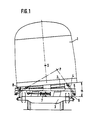
- Fig. 1 in schematischer Darstellung einen Querschnitt durch ein Schienenfahrzeug nach der Linie A-A in Fig. 2;
- Fig. 2 in schematischer Seitenansicht das Schienenfahrzeug nach Fig. 1 im Bereich eines Drehgestelles.
- Figure 1 is a schematic representation of a cross section through a rail vehicle along the line AA in Fig. 2.
- Fig. 2 in a schematic side view of the rail vehicle according to Fig. 1 in the region of a bogie.
Von dem in Fig.1 und 2 dargestellten Schienenfahrzeug, also beispielsweise einem Eisenbahnwaggon, sind nur die im Zusammenhang mit der Einrichtung zur Querneigung des Wagenkastens im Gleisbogen interessierenden Teile dargestellt.Of the rail vehicle shown in FIGS. 1 and 2, that is to say, for example, a railroad car, only the parts of interest in connection with the device for transverse inclination of the car body in the track curve are shown.
Es handelt sich um ein Schienenfahrzeug mit einem wiegenträgerlosen Drehgestell, bei dem sich der Wagenkasten 1 über das Federsystem 2 direkt auf dem Drehgestell 3 abstützt. Bei dieser Drehgestellbauart ist die Federung auch in der horizontalen Längsrichtung nachgiebig, so daß ein Ausdrehen des Drehgestells 3 um die vertikale Achse relativ zum Wagenkasten 1 möglich ist. Weiterhin ermöglicht die Nachgiebigkeit des Federsystems 2 in vertikaler und horizontaler Richtung die Neigung des Wagenkastens 1 um einen Drehpol P, der durch eine parallel zum Federsystem 2 liegende Neigungseinrichtung bestimmt wird.It is a rail vehicle with a bogie without a cradle, in which the
Diese Neigungseinrichtung weist zwei zueinander und zur Längsmittelebene des Wagens geneigte Pendel 4 auf, deren oberes Ende jeweils am Wagenkasten 1 und deren unteres Ende an einem Zwischenträger 5 befestigt ist. Die Neigung der Pendel 4 ist so gewählt, daß sich die Verlängerungen ihrer Mittellinien bei aufrecht stehendem Wagen auf der Höhe des Schwerpunkts S oder oberhalb dieser Höhe schneiden.This inclination device has two pendulums 4 inclined to each other and to the longitudinal center plane of the carriage, the upper end of which is fastened to the
Der Zwischenträger 5 wird durch eine an sich bekannte Wankstütze 6 annähernd parallel zur horizontalen xy-Ebene des Drehgestellrahmens 3 gehalten und durch eine Querfederung 7 in Querrichtung geführt.The
Die oben beschriebene Einrichtung zur Neigung des Wagenkastens in Querrichtung kann als aktives oder als passives System ausgebildet sein.The above-described device for inclining the car body in the transverse direction can be designed as an active or a passive system.
Bei einem aktiven System liegt der Schnittpunkt der Verlängerungen der Pendel 4 bei aufrecht stehendem Wagen mindestens angenähert in Höhe des Wagenkastenschwerpunktes S. Die Neigung des Wagenkastens 1 relativ zum Zwischenträger 5 beim Fahren durch einen Gleisbogen wird durch einen Stellantrieb erzwungen. Dieser Stellantrieb kann beispielsweise ein Elektromotor sein, der über ein nicht dargestelltes Getriebe auf den in Fig. 1 dargestellten Kurbelmechanismus 8 wirkt. Der Antrieb kann mit einem Regelsystem verbunden sein. Da derartige Antriebe und Regelsysteme an sich bekannt sind, werden sie im folgenden nicht näher erläutert.In an active system, the intersection of the extensions of the pendulum 4 when the car is upright is at least approximately at the level of the center of gravity S of the car body. This actuator can be an electric motor, for example, which acts on the crank mechanism 8 shown in FIG. 1 via a gear, not shown. The drive can be connected to a control system. Since such drives and control systems are known per se, they are not explained in more detail below.
Bei einem passiven System liegt der Schnittpunkt der Verlängerung der Mittellinien der Pendel 4 deutlich oberhalb des Schwerpunktes S des Wagenkastens 1. Unter dem Einfluß der Fliehkraft, die im Schwerpunkt S angreift, tendiert der Wagenkasten 1 dazu, auf dem querweichen Federsystem 2 nach Bogenaußen zu treiben, wird aber durch die schrägstehenden Pendel 4, deren Wirkungslinie in Höhe des Schnittpunkts der Mittellinien oberhalb des Schwerpunkts S liegt, gehalten. Auf diese Weise entsteht ein Moment, das den Wagenkasten 1 nach Bogeninnen neigt.In the case of a passive system, the intersection of the extension of the center lines of the pendulums 4 is clear above the center of gravity S of the
Aus dem dargestellten Ausführungsbeispiel ist ersichtlich, daß sich bei diesem System das Gewicht des Wagenkastens 1 nicht auf der Einrichtung zur Erzeugung der Querneigung abstützt. Diese Einrichtung hat daher nur Stellkräfte zu übertragen, die sehr viel kleiner sind als das Wagenkastengewicht und kann deshalb erheblich leichter gebaut sein als bei herkömmlichen Systemen.From the illustrated embodiment it can be seen that in this system the weight of the
Das anhand der Fig. 1 und 2 beschriebene System ist auch anwendbar in Verbindung mit einem Wiegenträger.The system described with reference to FIGS. 1 and 2 can also be used in connection with a cradle.
Bei Anordnung des Wiegenträgers unterhalb des Federsystems 2 stützen sich Feder 2 und Wankstütze 6 auf diesem Wiegenträger ab. Der Wiegenträger wird über seitliche Anlenkstangen (an jeder Wagenseite eine) gegen den Wagenkasten geführt.When the cradle is arranged below the
Bei Anordnung des Wiegenträgers oberhalb des Federsystems 2 ist der Wiegenträger gegen den Drehgestellrahmen durch seitliche Anlenkstangen oder Gleitflächen geführt. In diesem Falle schließen die schrägstehenden Pendel 4 der Neigungseinrichtung am Wiegenträger an und nicht am Wagenkasten.When the cradle is arranged above the
Claims (3)
Applications Claiming Priority (2)
| Application Number | Priority Date | Filing Date | Title |
|---|---|---|---|
| DE19873713615 DE3713615A1 (en) | 1987-04-23 | 1987-04-23 | RAIL VEHICLE WITH CROSS-TILTING DEVICE |
| DE3713615 | 1987-04-23 |
Publications (3)
| Publication Number | Publication Date |
|---|---|
| EP0287821A2 true EP0287821A2 (en) | 1988-10-26 |
| EP0287821A3 EP0287821A3 (en) | 1989-02-01 |
| EP0287821B1 EP0287821B1 (en) | 1990-10-10 |
Family
ID=6326148
Family Applications (1)
| Application Number | Title | Priority Date | Filing Date |
|---|---|---|---|
| EP88104511A Expired - Lifetime EP0287821B1 (en) | 1987-04-23 | 1988-03-22 | Railway vehicle with tilting mechanism |
Country Status (4)
| Country | Link |
|---|---|
| EP (1) | EP0287821B1 (en) |
| DE (2) | DE3713615A1 (en) |
| DK (1) | DK163722C (en) |
| NO (1) | NO170067C (en) |
Cited By (8)
| Publication number | Priority date | Publication date | Assignee | Title |
|---|---|---|---|---|
| DE4112879A1 (en) * | 1990-12-14 | 1992-10-29 | Rexroth Mannesmann Gmbh | Wagon body tipping system - has fluid draining from tipping system's hydraulic cylinders fed directly to pressure side of transverse cylinders, and vice=versa |
| EP0621165A1 (en) * | 1993-04-22 | 1994-10-26 | ABB HENSCHEL WAGGON UNION GmbH | Running gear for railway vehicles |
| WO1995026291A1 (en) * | 1994-03-29 | 1995-10-05 | Waggonfabrik Talbot Gmbh & Co. Kg | Anti-roll support for rail vehicles with a transverse tilting device |
| DE19500212A1 (en) * | 1995-01-05 | 1996-08-29 | Nusser Josef | Swivel connector for railway vehicles |
| WO1998026970A1 (en) * | 1996-12-19 | 1998-06-25 | Siemens Sgp Verkehrstechnik Gmbh | Truck frame for railway rolling stock |
| EP0987161A2 (en) | 1998-09-16 | 2000-03-22 | ALSTOM LHB GmbH | Device for tilting a body of a railway vehicle suspended by a running gear around a longitudinal axis, incorporating an anti-roll support |
| US7438000B2 (en) | 2002-09-05 | 2008-10-21 | Bombardier Transportation Gmbh | Running gear for rail vehicles |
| AT514029A1 (en) * | 2013-01-22 | 2014-09-15 | Siemens Ag Oesterreich | Rail vehicle with tilting technology |
Families Citing this family (6)
| Publication number | Priority date | Publication date | Assignee | Title |
|---|---|---|---|---|
| DE4311521C1 (en) * | 1993-04-07 | 1994-04-21 | Talbot Waggonfab | Support against unsteadiness in rail vehicle - has cross inclination control with length-alterable, adjustable connecting piece controlled by drive component |
| DE4421000B4 (en) * | 1993-06-16 | 2013-06-06 | Josef Nusser | Rail vehicle with turning device |
| DE4343998A1 (en) * | 1993-12-22 | 1995-07-20 | Josef Nusser | Tilt control for railway vehicle |
| DE4444540B4 (en) * | 1994-06-16 | 2015-08-06 | Josef Nusser | Rail vehicle with turning device |
| DE19522378B4 (en) * | 1994-12-22 | 2017-03-16 | Josef Nusser | Device for rail vehicles for tilt regulation of the car body |
| AT514374A1 (en) * | 2013-05-02 | 2014-12-15 | Siemens Ag Oesterreich | Chassis frame for a rail vehicle |
Citations (5)
| Publication number | Priority date | Publication date | Assignee | Title |
|---|---|---|---|---|
| FR1423899A (en) * | 1964-11-25 | 1966-01-07 | Sncf | Pendulum suspension device for the body of vehicles, particularly railway vehicles |
| US3717104A (en) * | 1970-07-08 | 1973-02-20 | United Aircraft Corp | Active roll controling truck stabilizing mechanism |
| US3906869A (en) * | 1974-09-16 | 1975-09-23 | Dominion Foundries & Steel | Safety device for banking vehicles |
| FR2434739A1 (en) * | 1978-09-04 | 1980-03-28 | Schweizerische Lokomotiv | VEHICLE ON RAILS |
| EP0189382A2 (en) * | 1985-01-18 | 1986-07-30 | FIAT FERROVIARIA SAVIGLIANO S.p.A. | High-speed railway vehicle with a variable-attitude body |
-
1987
- 1987-04-23 DE DE19873713615 patent/DE3713615A1/en not_active Withdrawn
-
1988
- 1988-03-22 EP EP88104511A patent/EP0287821B1/en not_active Expired - Lifetime
- 1988-03-22 DE DE8888104511T patent/DE3860770D1/en not_active Expired - Lifetime
- 1988-04-21 NO NO881735A patent/NO170067C/en unknown
- 1988-04-22 DK DK221188A patent/DK163722C/en not_active IP Right Cessation
Patent Citations (5)
| Publication number | Priority date | Publication date | Assignee | Title |
|---|---|---|---|---|
| FR1423899A (en) * | 1964-11-25 | 1966-01-07 | Sncf | Pendulum suspension device for the body of vehicles, particularly railway vehicles |
| US3717104A (en) * | 1970-07-08 | 1973-02-20 | United Aircraft Corp | Active roll controling truck stabilizing mechanism |
| US3906869A (en) * | 1974-09-16 | 1975-09-23 | Dominion Foundries & Steel | Safety device for banking vehicles |
| FR2434739A1 (en) * | 1978-09-04 | 1980-03-28 | Schweizerische Lokomotiv | VEHICLE ON RAILS |
| EP0189382A2 (en) * | 1985-01-18 | 1986-07-30 | FIAT FERROVIARIA SAVIGLIANO S.p.A. | High-speed railway vehicle with a variable-attitude body |
Cited By (13)
| Publication number | Priority date | Publication date | Assignee | Title |
|---|---|---|---|---|
| DE4112879C2 (en) * | 1990-12-14 | 2000-08-31 | Mannesmann Rexroth Ag | Car body tilt system |
| DE4112879A1 (en) * | 1990-12-14 | 1992-10-29 | Rexroth Mannesmann Gmbh | Wagon body tipping system - has fluid draining from tipping system's hydraulic cylinders fed directly to pressure side of transverse cylinders, and vice=versa |
| EP0621165A1 (en) * | 1993-04-22 | 1994-10-26 | ABB HENSCHEL WAGGON UNION GmbH | Running gear for railway vehicles |
| WO1995026291A1 (en) * | 1994-03-29 | 1995-10-05 | Waggonfabrik Talbot Gmbh & Co. Kg | Anti-roll support for rail vehicles with a transverse tilting device |
| DE19500212A1 (en) * | 1995-01-05 | 1996-08-29 | Nusser Josef | Swivel connector for railway vehicles |
| WO1998026970A1 (en) * | 1996-12-19 | 1998-06-25 | Siemens Sgp Verkehrstechnik Gmbh | Truck frame for railway rolling stock |
| CN1098185C (en) * | 1996-12-19 | 2003-01-08 | 西门子Sgp交通技术有限公司 | Truck frame for railway rolling stock |
| CZ297368B6 (en) * | 1996-12-19 | 2006-11-15 | Siemens Transportation Systems Gmbh & Co Kg | Pivoted bogie for rail vehicle |
| EP0987161A2 (en) | 1998-09-16 | 2000-03-22 | ALSTOM LHB GmbH | Device for tilting a body of a railway vehicle suspended by a running gear around a longitudinal axis, incorporating an anti-roll support |
| US7438000B2 (en) | 2002-09-05 | 2008-10-21 | Bombardier Transportation Gmbh | Running gear for rail vehicles |
| AT514029A1 (en) * | 2013-01-22 | 2014-09-15 | Siemens Ag Oesterreich | Rail vehicle with tilting technology |
| AT514029B1 (en) * | 2013-01-22 | 2015-05-15 | Siemens Ag Oesterreich | Rail vehicle with tilting technology |
| US9701322B2 (en) | 2013-01-22 | 2017-07-11 | Siemens Ag Oesterreich | Rail vehicle having tilting technology |
Also Published As
| Publication number | Publication date |
|---|---|
| DE3860770D1 (en) | 1990-11-15 |
| EP0287821B1 (en) | 1990-10-10 |
| DK221188D0 (en) | 1988-04-22 |
| EP0287821A3 (en) | 1989-02-01 |
| DE3713615A1 (en) | 1988-11-17 |
| NO170067C (en) | 1992-09-09 |
| DK163722B (en) | 1992-03-30 |
| DK163722C (en) | 1992-09-07 |
| DK221188A (en) | 1988-10-24 |
| NO881735D0 (en) | 1988-04-21 |
| NO881735L (en) | 1988-10-24 |
| NO170067B (en) | 1992-06-01 |
Similar Documents
| Publication | Publication Date | Title |
|---|---|---|
| EP0287821B1 (en) | Railway vehicle with tilting mechanism | |
| DE741874C (en) | Device for automatic compensation of centrifugal forces in vehicles | |
| EP0393177B1 (en) | Tilt compensator for high-speed vehicles, in particular rail vehicles | |
| EP0370168B1 (en) | Propulsion unit for a vehicle in a driverless transport system | |
| DE3019468C2 (en) | Undercarriage for railway vehicles | |
| EP1610995B1 (en) | Running gear for a railway vehicle provided with an improved transversal suspension | |
| EP0017856B1 (en) | Suspension for transport means | |
| DE2142975A1 (en) | Suspensions for high-speed vehicles, especially for railroad cars | |
| EP0944513A1 (en) | Truck frame for railway rolling stock | |
| DE1920705A1 (en) | Rear axle suspension of motor vehicles | |
| CH676220A5 (en) | ||
| EP1572516B1 (en) | Running gear for rail vehicles | |
| DE2145738C3 (en) | Rail vehicle with curved track control | |
| EP0273940B1 (en) | Mechanical device for stabilizing rail vehicles | |
| DE2438570A1 (en) | SUSPENSION FOR A CONVEYOR | |
| CH658431A5 (en) | Waggon suspension for rail vehicle | |
| DE3428159C2 (en) | Axle suspension for motor vehicles, in particular passenger cars | |
| CH659218A5 (en) | JOINT CONTROL DEVICE ON A FOUR-AXLE RAIL VEHICLE. | |
| AT396096B (en) | SECONDARY SPRING FOR A ROTATION OF A RAIL VEHICLE | |
| EP0714358B1 (en) | Couplable bogie designed to carry and tilt a railway-carriage body | |
| EP0624506B1 (en) | Lever arrangement for transversely movable brake shoe assemblies at railway vehicles | |
| DE2147900C3 (en) | Railway train made up of several different vehicles, including those with swinging, tilting car bodies | |
| EP0299318A2 (en) | Undercarriage for railway vehicles with magnetic track brake or eddy current brake | |
| CH617135A5 (en) | Rail power unit | |
| DE2201255A1 (en) | Rail vehicle |
Legal Events
| Date | Code | Title | Description |
|---|---|---|---|
| PUAI | Public reference made under article 153(3) epc to a published international application that has entered the european phase |
Free format text: ORIGINAL CODE: 0009012 |
|
| AK | Designated contracting states |
Kind code of ref document: A2 Designated state(s): CH DE FR GB IT LI SE |
|
| PUAL | Search report despatched |
Free format text: ORIGINAL CODE: 0009013 |
|
| AK | Designated contracting states |
Kind code of ref document: A3 Designated state(s): CH DE FR GB IT LI SE |
|
| 17P | Request for examination filed |
Effective date: 19890315 |
|
| RAP1 | Party data changed (applicant data changed or rights of an application transferred) |
Owner name: WAGGONFABRIK TALBOT |
|
| 17Q | First examination report despatched |
Effective date: 19900314 |
|
| GRAA | (expected) grant |
Free format text: ORIGINAL CODE: 0009210 |
|
| AK | Designated contracting states |
Kind code of ref document: B1 Designated state(s): CH DE FR GB IT LI SE |
|
| GBT | Gb: translation of ep patent filed (gb section 77(6)(a)/1977) | ||
| ET | Fr: translation filed | ||
| REF | Corresponds to: |
Ref document number: 3860770 Country of ref document: DE Date of ref document: 19901115 |
|
| ITF | It: translation for a ep patent filed |
Owner name: ING. ZINI MARANESI & C. S.R.L. |
|
| PLBE | No opposition filed within time limit |
Free format text: ORIGINAL CODE: 0009261 |
|
| STAA | Information on the status of an ep patent application or granted ep patent |
Free format text: STATUS: NO OPPOSITION FILED WITHIN TIME LIMIT |
|
| 26N | No opposition filed | ||
| ITTA | It: last paid annual fee | ||
| EAL | Se: european patent in force in sweden |
Ref document number: 88104511.6 |
|
| PGFP | Annual fee paid to national office [announced via postgrant information from national office to epo] |
Ref country code: GB Payment date: 19950306 Year of fee payment: 8 |
|
| PGFP | Annual fee paid to national office [announced via postgrant information from national office to epo] |
Ref country code: FR Payment date: 19950317 Year of fee payment: 8 |
|
| PGFP | Annual fee paid to national office [announced via postgrant information from national office to epo] |
Ref country code: SE Payment date: 19950324 Year of fee payment: 8 |
|
| PGFP | Annual fee paid to national office [announced via postgrant information from national office to epo] |
Ref country code: CH Payment date: 19950418 Year of fee payment: 8 |
|
| PGFP | Annual fee paid to national office [announced via postgrant information from national office to epo] |
Ref country code: DE Payment date: 19950517 Year of fee payment: 8 |
|
| PG25 | Lapsed in a contracting state [announced via postgrant information from national office to epo] |
Ref country code: GB Effective date: 19960322 |
|
| PG25 | Lapsed in a contracting state [announced via postgrant information from national office to epo] |
Ref country code: SE Effective date: 19960323 |
|
| PG25 | Lapsed in a contracting state [announced via postgrant information from national office to epo] |
Ref country code: LI Effective date: 19960331 Ref country code: CH Effective date: 19960331 |
|
| GBPC | Gb: european patent ceased through non-payment of renewal fee |
Effective date: 19960322 |
|
| REG | Reference to a national code |
Ref country code: CH Ref legal event code: PL |
|
| PG25 | Lapsed in a contracting state [announced via postgrant information from national office to epo] |
Ref country code: FR Effective date: 19961129 |
|
| PG25 | Lapsed in a contracting state [announced via postgrant information from national office to epo] |
Ref country code: DE Effective date: 19961203 |
|
| EUG | Se: european patent has lapsed |
Ref document number: 88104511.6 |
|
| REG | Reference to a national code |
Ref country code: FR Ref legal event code: ST |
|
| PG25 | Lapsed in a contracting state [announced via postgrant information from national office to epo] |
Ref country code: IT Free format text: LAPSE BECAUSE OF NON-PAYMENT OF DUE FEES;WARNING: LAPSES OF ITALIAN PATENTS WITH EFFECTIVE DATE BEFORE 2007 MAY HAVE OCCURRED AT ANY TIME BEFORE 2007. THE CORRECT EFFECTIVE DATE MAY BE DIFFERENT FROM THE ONE RECORDED. Effective date: 20050322 |