EP0287335A2 - Tablet dispenser having feed assist means - Google Patents
Tablet dispenser having feed assist means Download PDFInfo
- Publication number
- EP0287335A2 EP0287335A2 EP88303289A EP88303289A EP0287335A2 EP 0287335 A2 EP0287335 A2 EP 0287335A2 EP 88303289 A EP88303289 A EP 88303289A EP 88303289 A EP88303289 A EP 88303289A EP 0287335 A2 EP0287335 A2 EP 0287335A2
- Authority
- EP
- European Patent Office
- Prior art keywords
- tablet
- tablets
- dispenser
- container
- reciprocal
- Prior art date
- Legal status (The legal status is an assumption and is not a legal conclusion. Google has not performed a legal analysis and makes no representation as to the accuracy of the status listed.)
- Withdrawn
Links
Images

Classifications
-
- B—PERFORMING OPERATIONS; TRANSPORTING
- B65—CONVEYING; PACKING; STORING; HANDLING THIN OR FILAMENTARY MATERIAL
- B65D—CONTAINERS FOR STORAGE OR TRANSPORT OF ARTICLES OR MATERIALS, e.g. BAGS, BARRELS, BOTTLES, BOXES, CANS, CARTONS, CRATES, DRUMS, JARS, TANKS, HOPPERS, FORWARDING CONTAINERS; ACCESSORIES, CLOSURES, OR FITTINGS THEREFOR; PACKAGING ELEMENTS; PACKAGES
- B65D83/00—Containers or packages with special means for dispensing contents
- B65D83/04—Containers or packages with special means for dispensing contents for dispensing annular, disc-shaped, spherical or like small articles, e.g. tablets or pills
- B65D83/0409—Containers or packages with special means for dispensing contents for dispensing annular, disc-shaped, spherical or like small articles, e.g. tablets or pills the dispensing means being adapted for delivering one article, or a single dose, upon each actuation
-
- B—PERFORMING OPERATIONS; TRANSPORTING
- B65—CONVEYING; PACKING; STORING; HANDLING THIN OR FILAMENTARY MATERIAL
- B65D—CONTAINERS FOR STORAGE OR TRANSPORT OF ARTICLES OR MATERIALS, e.g. BAGS, BARRELS, BOTTLES, BOXES, CANS, CARTONS, CRATES, DRUMS, JARS, TANKS, HOPPERS, FORWARDING CONTAINERS; ACCESSORIES, CLOSURES, OR FITTINGS THEREFOR; PACKAGING ELEMENTS; PACKAGES
- B65D2583/00—Containers or packages with special means for dispensing contents
- B65D2583/04—For dispensing annular, disc-shaped or spherical or like small articles or tablets
- B65D2583/0472—For dispensing annular, disc-shaped or spherical or like small articles or tablets characterised by the dispensing action
- B65D2583/0477—For dispensing annular, disc-shaped or spherical or like small articles or tablets characterised by the dispensing action the container is maintained in the same position during the dispensing of several successive articles or doses
- B65D2583/0481—One reciprocating action, e.g. to or from
Definitions
- the present invention relates generally to an article dispensing device, and more particularly, to a tablet dispenser having a feed assist means to prevent bridging of tablets in the dispensing of a solid tablet or a predetermined number of such tablets of substantially uniform size from a storage area containing a relatively large number of tablets into a dispensing orifice upon operation of an actuating mechanism.
- the present invention is particularly useful for dispensing disc-shaped reagent tablets in an automated clinical chemistry analyzer.
- reagent tablets in clinical chemistry analyzers are highly moisture-sensitive and, therefore, must be protected at all times from being exposed to even normal room humidity. Such exposure to ambient moisture will cause premature degradation of the reagent tablets, which may lead to inaccurate test readings. In addition, exposure to moisture may also cause the tablets to swell in size which may interfere with the reliable operation of the tablet dispenser.
- a tablet dispenser which cures the above problem. It dispenses a solid tablet or a predetermined number of tablets of a substantially uniform size from a storage area containing a relatively large number of tablets into a dispensing orifice upon operation of an external actuating mechanism.
- the tablet dispenser comprises a hollow body having an upper portion for storing the relatively large number of tablets and a lower base having the dispensing orifice formed in its bottom. Above the tablet dispensing orifice a gate member is mounted for reciprocal movement. The gate has a tablet receiving area formed therein. A field organizing member is mounted below the tablet storage portion and above the gate member. The organizing member, mounted for reciprocal movement, has a tablet receiving area formed therein which communicates with the tablet storage portion.
- a means interconnects the gate member and organizing member, this interconnecting means causing them to reciprocate in directions opposite each other whereby the gate member may be reciprocated from a tablet dispense position, wherein its tablet receiving area is in communication with the tablet dispensing orifice, to a tablet receiving position, wherein its tablet receiving area is in communication with the tablet receiving area of the organizing member.
- An actuating means is further included for causing reciprocal movement of the gate member and organizing member in response to the operation of the external actuating mechanism.
- Bridging is a structured union of tablets forming a rigid, though perhaps fragile, structure between fixed walls which prevents the tablets from reaching the dispensing orifice.
- This bridging or umbrella effect usually occurs in the storage means or at some point before the articles reach the dispensing orifice.
- a bridging effect is most likely to occur when two or more tablets make contact with the interior walls of the storage means.
- factors include the weight of the articles in the bridge, weight of the articles on the bridge, coefficients of friction of the articles, coefficients of friction of the interior walls, temperature, humidity, static charge, shape of the tablets, shape and angles of the interior walls of the dispensing device and other similar factors.
- One previously used method of breaking up such a bridge among the articles is to place a wishbone-type member above the field organizing member in the upper storage portion of the hollow body in a device such as that disclosed in U.S. 4,405,060.
- the wishbone type member was V-shaped with its two legs joined at a base portion having a mounting hole.
- the wishbone-type member was pivotally mounted on a pin attached to the inside of the upper storage portion of the hollow body with the legs hanging down towards the field organizing member, the ends of the legs being in contact with and moving with the organizing member.
- the organizing member was reciprocated the wishbone-type member pivoted about the pin and tended to break up any bridged tablets surrounding it, by not allowing any structure support of this bridge.
- the present invention pertains to a different and novel structure for providing such anti-bridging action.
- a tablet dispenser having a feed assist means to prevent bridging of tablets.
- a flexible wall is provided in the feed channel.
- the flexible wall is made of a resilient material having a thickness and shape to allow for a temporary reshaping.
- Opposite the flexible wall is a rigid tapered wall to direct the tablets, in cooperation with the flexible wall, in a downward funnel type action towards an organizing member.
- the flexible wall has a first end which is attached to the organizing member and is thereby moved upon movement of the organizing organizing member. A second end of the flexible wall is attached to a stationing portion of the dispenser.
- the flexible wall in response to movement of the organizing member and in cooperation with the other walls in the feed channel, agitates and vibrates the tablets in the storage chamber thereby preventing the bridging of tablets and assisting in the feeding of the tablets to a dispensing orifice.
- a feed assist means is provided with two flexible walls located in the feed channel which are substantially similar to the flexible wall described in the above-described embodiment.
- the first ends of the flexible walls are attached to the organizing member adjacent opposite ends of a tablet receiving area, respectively.
- the second ends of the flexible walls are attached to stationary portions of the dispenser.
- the two flexible walls thus form a type of vibrating and agitating funnel to guide the tablets toward the dispensing orifice while preventing the bridging of the tablets.
- the claimed invention is capable of operation in any type of dispensing device having an internally moving mechanism.
- the invention as hereinafter employed is described in use with a tablet dispensing device.
- Tablet dispenser 10 comprises a hollow body 12 having an upper portion 14 adapted for storing a relatively large number of tablets 20, and a lower base portion 16 having a dispensing orifice 30 formed in its bottom 18 of the dispenser or, for greater accuracy in dispensing tablet 21 into cuvette 81 the dispensing orifice may be downwardly extended as a barrel (not shown).
- a gate member 40 is mounted within base portion 16 for reciprocal movement as shown by the directional arrows A above tablet dispensing orifice 30.
- gate member 40 is formed as an elongated horizontal bar 42 having its bottom surface 44 resting on the inner bottom surface 17 of base portion 16.
- Gate member 40 has a tablet receiving area 46 formed therein which, in the preferred embodiment, is formed as a slot 48 extending through elongated bar 42. The dimensional size of slot 48 is selected to permit a single tablet 21 (or a predetermined number of tablets in a multitablet dispense system) to enter and be held therein when gate member 40 is in its tablet receive position as illustrated in Figure 4.
- a field organizing member 50 is also mounted within base portion 16 for reciprocal movement below tablet storage portion 14 and above gate member 40 as shown by directional arrows B .
- field organizing member 50 is constructed essentially as a T-shaped member having an upper horizontal section 52 and feed slide section 54 depending downwardly from horizontal section 52.
- a tablet receiving area 56 is formed through both upper horizontal section 52 and feed slide section 54 which communicates with tablet storage portion 14. As best shown in Figures 4 and 5, tablet receiving area 56, as it extends through feed slide section 54, is of sufficient length to store a number of tablets 20 in a single, substantially vertical stack. In this manner, the randomly arranged tablets 20 contained in storage portion 14 are organized into a single vertical column above gate member 40.
- the column of tablets 20 in the tablet receiving area 56 acts as a sub-storage unit to temporarily supply tablets to the slot 48 for dispensing.
- agitator means 58 which engages tablets 20 contained in storage portion 14.
- agitator means 58 consists of a concave channel 59, formed in the upper surface 53 of horizontal section 52, which communicates with and guides tablets into the tablet receiving area 56 due to its concave shape.
- the length of tablet receiving area 56 is selected so that it will store an integral number of tablets of a predetermined diameter, and concave channel 59 has an overall depth of slightly less than half of the diameter of tablet 21.
- feed channel 32 is formed to be mounted into a corresponding receiving portion 15 formed in the lower area of the tablet storage portion 14.
- the feed channel 32 has a rigid portion 35 and a resilient portion 28.
- the rigid portion 35 has an inner tapered wall 33 which tapers from the lower end of storage portion 14 to the concave channel 59 of organizing member 50.
- the resilient portion 28 has two attached ends 23 and 25.
- the first end 23 is attached to the organizing member 50 at a point adjacent to the concave channel 59 of the agitator means 58.
- the second end 25 is attached to a stationary rigid portion 35 of the feed channel 32.
- the attachments of the ends 23 and 25 may be by any suitable means, such as being made hinged, pivotal, permanent or even detachable so as to facilitate assembly and disassembly.
- the resulting shape of the resilient portion 28 is a semi-rigid bow shape so as to facilitate the feeding of the tablets 20 towards the receiving area 56. However, as described below, any suitable shape may be employed.
- the resilient portion 28 can be made of any suitable material known in the art, such as plastic, rubber or elastomer thus producing a flexible wall in the feed channel.
- the width of the wall 28 is substantially equivalent to the width of the inner feed channel 32.
- the wall 28 is able to move without any substantial interference from the sidewalls in the feed channel 32.
- the length and thickness of the wall combine to produce the proper resiliency needed in the feed channel.
- the thickness, length or width may be made variable to better contribute in preventing the bridging of the tablets.
- the first end 23 of the resilient portion 28 moves with the movement of the organizing member 50 as shown by directional arrows B, thereby changing the shape or position of the resilient member and moving the tablets 20 in the feed channel 32.
- the movement of the tablets 20 in the feed channel 32 results from a first movement of the organizing member 50, as shown in Figure 5, causing a portion of the flexible wall 28 to move away from the tablets thereby removing support from on side of the tablets 20 in the feed channel 32 causing them to vibrate and move.
- the resilient member 28 Upon movement back to its initial starting point, as shown in Figure 4, the resilient member 28 will again move the tablets 20 in the feed channel 32 and thereby regain its original bow shape.
- the second movement of the organizing member 50 and the resulting movement of tablets 20 occurs from the exertion of force by the resilient portion 28 pushing and vibrating the tablets.
- the shape of the resilient member need only be shaped to facilitate the downward movement of the tablets 20 and upon movement to agitate the tablets 20 in the feed channel 12.
- the first end 23 of the resilient member 28 may be connected to a slidable mechanism located within the rigid portion 35. The slidable mechanism would move with the organizing member 50 thereby moving the resilient member 28 by means of moving its first end 23.
- the inner areas 34 formed by the tapered wall 33 and resilient portion 28 of feed channel 32 may be utilized as a storage area for desiccant material (not shown) used for absorbing any moisture which may penetrate hollow body 12. It should be noted that if it is not desired to utilize inner areas 34 for storage for desiccant material, feed channel 32 may be integrally formed as a part of tablet storage portion 14 in order to reduce manufacturing and assembly cost.
- Interconnecting member 60 Located between gate member 40 and organizing member 50 is an interconnecting member 60 which is utilized to reciprocate these members in directions opposite each other as is best shown in Figures 4 and 5.
- Interconnecting member 60 is formed in this embodiment of the invention as a compressible lever arm 62, shaped in the general configuration of a figure eight, having one of its ends 64 pivotably fitted within an engaging notch 51 formed in the underside of horizontal section 52 of organizing member 50 and its other end 65 pivotably fitted within a similar engaging notch 41 formed in the upper side of elongated bar 42 of gate member 40.
- Lever arm 62 is also pivotably mounted at its center by shafts 66 which engage mating receptacles 19 formed in the side walls of lower base portion 16.
- FIG. 6 an enlarged sectional view of the feed channel 32 and organizing member 50 is shown.
- a bridging of tablets 20 has formed in the feed channel 32 between the tapered wall 33 and the resilient portion 28.
- the resilient member 28 moves, as shown in Figure 7, thereby moving or repositioning the support on one side of the bridging and causing the bridge of tablets 20 to move or vibrate and collapse (such as partially due to their own unsupported weight) into a proper feeding position, as shown in Figure 7.
- the resilient member 28 moves back to its original position as the organizing member 50 moves back to its original position once again agitating the tablets 20 in the feed channel 32.
- Compressible lever arm 62 serves several functions in the preferred embodiment apart from simply interconnecting gate member 40 and organizing member 50. It also acts as a spring which maintains gate member 40 securely against inner bottom surface 17 of the tablet dispenser base portion 16. Furthermore, since this compressed arm will continuously seek to expand to its greatest length, it will also serve as a detent mechanism which will tend to urge and lock gate member 40 and organizing member 50 in their fully reciprocated positions shown in Figures 4 and 5.
- actuating means 70 Secured to feed slide section 54 of organizing member 50 is an actuating means 70 which causes reciprocal movement of the dispenser operating mechanism in response to an external actuating mechanism.
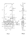
- This external actuator is illustrated in Figure 1 as a C-shaped member 80 into which T-portion 74 or other suitable engaging member formed on the external end of actuator arm 72 may be positioned.
- the end 76 of actuator arm 72 opposite T-portion 74 is seated in a groove portion 55 formed in feed slide section 54.
- Adjacent to actuator arm end 76 is formed a notch area 78 which engages a compression spring 57 extending from the bottom end of feed slide section 54.
- Compression spring 57 also cooperates with compressible lever arm 62 to maintain gate member 40 securely against bottom 18 of tablet dispenser base portion 16.
- a smaller surface area extended portion 43 may be formed on the underside of compression spring 57 which engages and reciprocates across surface 45.
- FIG. 1 through 5 The embodiment of the present invention illustrated in Figures 1 through 5 is shown as providing a hermetical seal about the tablets contained in the dispenser. Due to the reciprocating nature of gate member 40 with respect to dispensing orifice 30 and field organizing member 50, no unsealed opening to ambient air exists which may permit moisture penetration into the dispenser. This remains true even during the dispensing of a tablet as is illustrated in Figure 5.
- the hermetical seal system of this embodiment of the invention consists of an O-ring 82 which is sealingly disposed between the outer lip 22 of tablet storage portion 14 and inner lip 24 of the dispenser base portion 16.
- Storage portion 14 is maintained in mating engagement with base portion 16 by means of a snap lock 36.
- snap lock 36 consists of a series of fingers 37 formed on opposite sides of base portion 16 which lockingly engage a corresponding series of opening 38 formed in skirt portions 26 which downwardly depend from opposite sides of tablet storage portion 14.
- fingers 37 may be formed with a fish hook shape which do not permit the separation of the storage portion 14 and base portion 16 once joined in assembly.
- a bellows-type seal 84 encloses the opening in base portion 16 where actuator arm 72 enters it.
- guide 26 Surrounding this opening is guide 26 which is formed as a part of base portion 16.
- Guide 26 serves to align and support actuator arm 72, and it has a channel 27 formed about its periphery into which one of the ends of seal 84 sealingly fits.
- the other end of seal 84 similarly engages a channel 73 formed about the periphery of actuator arm 72, thereby completing the seal of this opening into the interior of dispenser body 12.
- O-ring 82 and bellows seal 84 may be constructed of rubber, elastomer or other material which provides a satisfactory moisture barrier and which is sufficiently resilient to satisfy the operational requirements of the seal.
- dispenser body 12 The only other opening into dispenser body 12 is through tablet dispensing orifice 30. This opening is maintained constantly sealed, even during actuation of the dispenser, through the interaction of gate member 40 with orifice 30 and feed slide section 54 of field organizing member 50.
- sealing material 86 Disposed on the inner surface of base bottom 18 is a sealing material 86 which may be made of urethane or similar material.
- a tablet ramp 87 is formed in sealing material 86 which communicates at its lower end with dispensing orifice 30 and at its upper end with slot 48 of gate member 40 when in its tablet dispense position illustrated by Figure 5.
- the bottom surface 44 of gate member horizontal bar 42 sealingly engages the upper surface 17 of sealing material 86, which becomes the inner bottom surface of base portion 16.
- a pair of mounting ears 11 are formed along the lateral edge of dispenser body 12 which frictionally secure the dispenser to an appropriate carrying mechanism within the instrument.
- insert guides 13 are formed on the side faces of dispenser body 12 in order to aid in orienting the dispenser within the instrument carrying mechanism. Mounting ears 11 and insert guides 13 must be precisely located on the dispenser body 12 with respect to orifice 30 in order to insure that the orifice will be properly aligned with respect to cuvette 81 when it is positioned at the tablet dispensing station.
- the feed channel 32 and organizing member 50 are shown.
- the feed channel 32 has two resilient portions 28 and 29.
- the resilient portions 28 and 29 form walls adjacent the tablets 20 in the feed channel 32.
- the first resilient portion 28 is attached at its first end 23 to the organizing member 50 at a point adjacent to the concave channel 59 of the agitator means 58.
- the second end 25 of the first resilient portion 28 is attached to rigid portion 35.
- the second resilient portion 29 forms a wall opposite the first resilient portion 28.
- the second portion 29 has a first end 93 attached to the organizing member 50 at a point adjacent to the concave channel 59 of the agitator means 58 opposite the first resilient portion end 23.
- the second end 95 of the second resilient portion 29 is attached to rigid portion 35 opposite the second end 25 of the first resilient portion 28.
- the two resilient walls thus form a type of flexible funnel for the tables.
- the movement of the organizing member 50 moves the respective first ends 23 and 93 of resilient portions 28 and 29.
- the two walls 28 and 29, thus move when the organizing member 50 is moved thereby agitating and vibrating the tablets in the feed channel 32 to prevent a bridging of tablets 20.
- a further alternative to the above-described embodiment would be to provide slidable members attached to the rigid portion 35 wherein the first end portions 23 and 93 are attached thereto and the slidable members move with the organizing member 50.
Landscapes
- Engineering & Computer Science (AREA)
- Mechanical Engineering (AREA)
- Coating Apparatus (AREA)
- Filling Or Emptying Of Bunkers, Hoppers, And Tanks (AREA)
- Automatic Analysis And Handling Materials Therefor (AREA)
- Medical Preparation Storing Or Oral Administration Devices (AREA)
Abstract
A tablet dispenser (10) having a feed channel (32) with a flexible wall (28) to prevent bridging of tablets (20). The flexible wall (28) moves in response to the movement of a tablet dispenser operating mechanism. The movement of the flexible wall (28) agitates the tablets (20) in the feed channel (32) to thereby prevent bridging of the tablets (20).
Description
- The present invention relates generally to an article dispensing device, and more particularly, to a tablet dispenser having a feed assist means to prevent bridging of tablets in the dispensing of a solid tablet or a predetermined number of such tablets of substantially uniform size from a storage area containing a relatively large number of tablets into a dispensing orifice upon operation of an actuating mechanism. The present invention is particularly useful for dispensing disc-shaped reagent tablets in an automated clinical chemistry analyzer.
- Various devices are known and used for dispensing solid articles or tablets upon operation of an actuation means. However, such known dispensers have numerous drawbacks which make their use impractical for certain applications, such as reagent dispensers in automated clinical chemistry analyzers.
- For example, since such automated analyzers are often left unattended, or the reagent dispensing takes place in an area where the operator cannot easily observe it, it is important that the dispenser reliably eject the exact number of tablets (generally a single reagent tablet) every time it is activated. Otherwise, a false test result could be obtained. Furthermore, even if the analyzer is equipped to detect the fact that the reagent tablet has not been properly dispensed, this generally occurs downstream of the dispensing station and, due to the sequential nature of the automated instrument, it is not possible to bring the material being tested back to the dispensing station for the ejection of another tablet. Hence, the material, such as blood serum, entered into the analyzer for testing will be wasted.
- Another problem encountered with the use of reagent tablets in clinical chemistry analyzers is that they are highly moisture-sensitive and, therefore, must be protected at all times from being exposed to even normal room humidity. Such exposure to ambient moisture will cause premature degradation of the reagent tablets, which may lead to inaccurate test readings. In addition, exposure to moisture may also cause the tablets to swell in size which may interfere with the reliable operation of the tablet dispenser.
- Even if the dispenser storage area in the analyzer is dehumidified, in many instances it is still desirable to provide additional moisture protection for the tablets since they must generally be transported to and from the instrument in the dispenser and, even while stored in the instrument, it is possible for the dispenser to be exposed to high humidity levels associated with the operation of many such instruments in the event of equipment failure. This could be a particularly serious problem since such reagent tablets are relatively expensive and several thousand of them are likely to be stored in the analyzer at any given time.
- In U.S. Patent No. 4,405,060 of P. Hsei, assigned to the same assignee as the present application, a tablet dispenser is provided which cures the above problem. It dispenses a solid tablet or a predetermined number of tablets of a substantially uniform size from a storage area containing a relatively large number of tablets into a dispensing orifice upon operation of an external actuating mechanism.
- The tablet dispenser comprises a hollow body having an upper portion for storing the relatively large number of tablets and a lower base having the dispensing orifice formed in its bottom. Above the tablet dispensing orifice a gate member is mounted for reciprocal movement. The gate has a tablet receiving area formed therein. A field organizing member is mounted below the tablet storage portion and above the gate member. The organizing member, mounted for reciprocal movement, has a tablet receiving area formed therein which communicates with the tablet storage portion. A means interconnects the gate member and organizing member, this interconnecting means causing them to reciprocate in directions opposite each other whereby the gate member may be reciprocated from a tablet dispense position, wherein its tablet receiving area is in communication with the tablet dispensing orifice, to a tablet receiving position, wherein its tablet receiving area is in communication with the tablet receiving area of the organizing member. An actuating means is further included for causing reciprocal movement of the gate member and organizing member in response to the operation of the external actuating mechanism.
- Occasionally a problem has been encountered in known and used devices wherein the feeding of the articles or tablets from the storing means to the dispensing orifice has resulted in producing a bridging or umbrella effect among the articles or tablets. Bridging is a structured union of tablets forming a rigid, though perhaps fragile, structure between fixed walls which prevents the tablets from reaching the dispensing orifice. This bridging or umbrella effect usually occurs in the storage means or at some point before the articles reach the dispensing orifice.
- A bridging effect is most likely to occur when two or more tablets make contact with the interior walls of the storage means. Several factors combined to produce this bridging effect. Such factors include the weight of the articles in the bridge, weight of the articles on the bridge, coefficients of friction of the articles, coefficients of friction of the interior walls, temperature, humidity, static charge, shape of the tablets, shape and angles of the interior walls of the dispensing device and other similar factors.
- The result is that these factors interact to produce a bridge or umbrella among the articles which prevents the articles above or on the bridge from effectively communicating with the mechanisms below the bridge. This bridging effect thus prevents the tablets from communicating with or reaching the dispensing area whereby the dispensing of articles may ultimately be permanently interrupted if not at least intermittently interrupted, producing false test results or wasted test material.
- One previously used method of breaking up such a bridge among the articles is to place a wishbone-type member above the field organizing member in the upper storage portion of the hollow body in a device such as that disclosed in U.S. 4,405,060. The wishbone type member was V-shaped with its two legs joined at a base portion having a mounting hole. The wishbone-type member was pivotally mounted on a pin attached to the inside of the upper storage portion of the hollow body with the legs hanging down towards the field organizing member, the ends of the legs being in contact with and moving with the organizing member. When the organizing member was reciprocated the wishbone-type member pivoted about the pin and tended to break up any bridged tablets surrounding it, by not allowing any structure support of this bridge.
- The present invention pertains to a different and novel structure for providing such anti-bridging action.
- The foregoing problems are overcome and other advantages are provided by a tablet dispenser having a feed assist means to prevent bridging of tablets.
- In one embodiment, a flexible wall is provided in the feed channel. The flexible wall is made of a resilient material having a thickness and shape to allow for a temporary reshaping. Opposite the flexible wall is a rigid tapered wall to direct the tablets, in cooperation with the flexible wall, in a downward funnel type action towards an organizing member. The flexible wall has a first end which is attached to the organizing member and is thereby moved upon movement of the organizing organizing member. A second end of the flexible wall is attached to a stationing portion of the dispenser. The flexible wall, in response to movement of the organizing member and in cooperation with the other walls in the feed channel, agitates and vibrates the tablets in the storage chamber thereby preventing the bridging of tablets and assisting in the feeding of the tablets to a dispensing orifice.
- In another embodiment a feed assist means is provided with two flexible walls located in the feed channel which are substantially similar to the flexible wall described in the above-described embodiment. The first ends of the flexible walls are attached to the organizing member adjacent opposite ends of a tablet receiving area, respectively. The second ends of the flexible walls are attached to stationary portions of the dispenser. The two flexible walls thus form a type of vibrating and agitating funnel to guide the tablets toward the dispensing orifice while preventing the bridging of the tablets.
-
- Figure 1 is a side plan view of a tablet dispenser;
- Figure 2 is an edge view of the tablet dispenser shown in Figure 1;
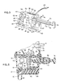
- Figure 3 is an enlarged perspective view of the tablet dispenser operating mechanism shown in Figure 1;
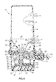
- Figure 4 is an enlarged side sectional view of the tablet dispenser shown in Figure 1 taken along line 4-4 of Figure 2 illustrating the dispenser gate member in its tablet receive position;
- Figure 5 is a partial side sectional view of the tablet dispenser similar to that shown in Figure 4 illustrating the dispenser gate member in its tablet dispense position.
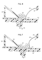
- Figure 6 is an enlarged sectional view of a tablet receiving area and feed channel with a bridging of tablets in the feed channel.
- Figure 7 is a sectional view of the feed channel having a flexible wall which moves to prevent bridging of tablets.
- Figure 8 is a sectional view of an alternative embodiment of the invention wherein the feed channel has two flexible walls as an anti-bridging device.
- Figure 9 is a sectional view of the device as in Figure 8 wherein the flexible walls are moved in response to the movement of an organizing member.
- As will be seen from the following description of the invention, the claimed invention is capable of operation in any type of dispensing device having an internally moving mechanism. However, for convenience, the invention as hereinafter employed is described in use with a tablet dispensing device.
- Referring to Figure 1 through 5, a
tablet dispenser 10 is shown.Tablet dispenser 10 comprises ahollow body 12 having anupper portion 14 adapted for storing a relatively large number oftablets 20, and alower base portion 16 having a dispensingorifice 30 formed in itsbottom 18 of the dispenser or, for greater accuracy in dispensingtablet 21 intocuvette 81 the dispensing orifice may be downwardly extended as a barrel (not shown). - A
gate member 40 is mounted withinbase portion 16 for reciprocal movement as shown by the directional arrows A abovetablet dispensing orifice 30. As is best shown in Figure 3 through 5,gate member 40 is formed as an elongatedhorizontal bar 42 having itsbottom surface 44 resting on theinner bottom surface 17 ofbase portion 16.Gate member 40 has atablet receiving area 46 formed therein which, in the preferred embodiment, is formed as a slot 48 extending through elongatedbar 42. The dimensional size of slot 48 is selected to permit a single tablet 21 (or a predetermined number of tablets in a multitablet dispense system) to enter and be held therein whengate member 40 is in its tablet receive position as illustrated in Figure 4. - A
field organizing member 50 is also mounted withinbase portion 16 for reciprocal movement belowtablet storage portion 14 and abovegate member 40 as shown by directional arrows B . In the preferred embodiment,field organizing member 50 is constructed essentially as a T-shaped member having an upperhorizontal section 52 andfeed slide section 54 depending downwardly fromhorizontal section 52. - A
tablet receiving area 56 is formed through both upperhorizontal section 52 andfeed slide section 54 which communicates withtablet storage portion 14. As best shown in Figures 4 and 5,tablet receiving area 56, as it extends throughfeed slide section 54, is of sufficient length to store a number oftablets 20 in a single, substantially vertical stack. In this manner, the randomly arrangedtablets 20 contained instorage portion 14 are organized into a single vertical column abovegate member 40. - In the event there is a temporary blockage of
tablets 20 in thestorage portion 14 the column oftablets 20 in thetablet receiving area 56 acts as a sub-storage unit to temporarily supply tablets to the slot 48 for dispensing. - Also located on organizing
member 50 is an agitator means 58 which engagestablets 20 contained instorage portion 14. In the preferred embodiment, agitator means 58 consists of aconcave channel 59, formed in theupper surface 53 ofhorizontal section 52, which communicates with and guides tablets into thetablet receiving area 56 due to its concave shape. As is shown in Figures 4 and 5, the length oftablet receiving area 56 is selected so that it will store an integral number of tablets of a predetermined diameter, andconcave channel 59 has an overall depth of slightly less than half of the diameter oftablet 21. With this design it is not possible for any of the randomly arrayedtablets 20 withinstorage portion 14 to become wedged within or under thelower edge portion 31 offeed channel 32, in which position they might be sheared in half or otherwise broken by the reciprocal movement of organizingmember 50. This is an extremely important consideration since the tests conducted by the chemical analyzer generally require that a precise amount of reagent be utilized in order to obtain accurate results. - As shown in Figures 4 and 5,
feed channel 32 is formed to be mounted into a corresponding receivingportion 15 formed in the lower area of thetablet storage portion 14. In this embodiment, thefeed channel 32 has arigid portion 35 and aresilient portion 28. Therigid portion 35 has an inner taperedwall 33 which tapers from the lower end ofstorage portion 14 to theconcave channel 59 of organizingmember 50. - In the present embodiment, the
resilient portion 28 has two attached ends 23 and 25. Thefirst end 23 is attached to the organizingmember 50 at a point adjacent to theconcave channel 59 of the agitator means 58. Thesecond end 25 is attached to a stationaryrigid portion 35 of thefeed channel 32. The attachments of theends resilient portion 28 is a semi-rigid bow shape so as to facilitate the feeding of thetablets 20 towards the receivingarea 56. However, as described below, any suitable shape may be employed. - The
resilient portion 28 can be made of any suitable material known in the art, such as plastic, rubber or elastomer thus producing a flexible wall in the feed channel. The width of thewall 28 is substantially equivalent to the width of theinner feed channel 32. As a result, thewall 28 is able to move without any substantial interference from the sidewalls in thefeed channel 32. In addition, the length and thickness of the wall combine to produce the proper resiliency needed in the feed channel. In an improvement on the flexible wall, the thickness, length or width may be made variable to better contribute in preventing the bridging of the tablets. - As shown in Figures 4 and 5, the
first end 23 of theresilient portion 28 moves with the movement of the organizingmember 50 as shown by directional arrows B, thereby changing the shape or position of the resilient member and moving thetablets 20 in thefeed channel 32. The movement of thetablets 20 in thefeed channel 32 results from a first movement of the organizingmember 50, as shown in Figure 5, causing a portion of theflexible wall 28 to move away from the tablets thereby removing support from on side of thetablets 20 in thefeed channel 32 causing them to vibrate and move. Upon movement back to its initial starting point, as shown in Figure 4, theresilient member 28 will again move thetablets 20 in thefeed channel 32 and thereby regain its original bow shape. The second movement of the organizingmember 50 and the resulting movement oftablets 20 occurs from the exertion of force by theresilient portion 28 pushing and vibrating the tablets. - In accordance with the invention the shape of the resilient member need only be shaped to facilitate the downward movement of the
tablets 20 and upon movement to agitate thetablets 20 in thefeed channel 12. In an alternate embodiment (not shown) thefirst end 23 of theresilient member 28 may be connected to a slidable mechanism located within therigid portion 35. The slidable mechanism would move with the organizingmember 50 thereby moving theresilient member 28 by means of moving itsfirst end 23. - The
inner areas 34 formed by the taperedwall 33 andresilient portion 28 offeed channel 32 may be utilized as a storage area for desiccant material (not shown) used for absorbing any moisture which may penetratehollow body 12. It should be noted that if it is not desired to utilizeinner areas 34 for storage for desiccant material,feed channel 32 may be integrally formed as a part oftablet storage portion 14 in order to reduce manufacturing and assembly cost. - Located between
gate member 40 and organizingmember 50 is an interconnectingmember 60 which is utilized to reciprocate these members in directions opposite each other as is best shown in Figures 4 and 5. Interconnectingmember 60 is formed in this embodiment of the invention as acompressible lever arm 62, shaped in the general configuration of a figure eight, having one of itsends 64 pivotably fitted within an engagingnotch 51 formed in the underside ofhorizontal section 52 of organizingmember 50 and itsother end 65 pivotably fitted within a similar engagingnotch 41 formed in the upper side ofelongated bar 42 ofgate member 40.Lever arm 62 is also pivotably mounted at its center byshafts 66 which engage mating receptacles 19 formed in the side walls oflower base portion 16. - Referring to Figures 6 and 7, an enlarged sectional view of the
feed channel 32 and organizingmember 50 is shown. In Figure 6, a bridging oftablets 20 has formed in thefeed channel 32 between thetapered wall 33 and theresilient portion 28. However, upon movement of the organizingmember 50 theresilient member 28 moves, as shown in Figure 7, thereby moving or repositioning the support on one side of the bridging and causing the bridge oftablets 20 to move or vibrate and collapse (such as partially due to their own unsupported weight) into a proper feeding position, as shown in Figure 7. Theresilient member 28 moves back to its original position as the organizingmember 50 moves back to its original position once again agitating thetablets 20 in thefeed channel 32. -
Compressible lever arm 62 serves several functions in the preferred embodiment apart from simply interconnectinggate member 40 and organizingmember 50. It also acts as a spring which maintainsgate member 40 securely againstinner bottom surface 17 of the tabletdispenser base portion 16. Furthermore, since this compressed arm will continuously seek to expand to its greatest length, it will also serve as a detent mechanism which will tend to urge and lockgate member 40 and organizingmember 50 in their fully reciprocated positions shown in Figures 4 and 5. - Secured to feed
slide section 54 of organizingmember 50 is an actuating means 70 which causes reciprocal movement of the dispenser operating mechanism in response to an external actuating mechanism. This external actuator is illustrated in Figure 1 as a C-shaped member 80 into which T-portion 74 or other suitable engaging member formed on the external end ofactuator arm 72 may be positioned. Theend 76 ofactuator arm 72 opposite T-portion 74 is seated in agroove portion 55 formed infeed slide section 54. Adjacent to actuatorarm end 76 is formed anotch area 78 which engages acompression spring 57 extending from the bottom end offeed slide section 54. This engagement permitsactuator arm 72 to urgefeed slide section 54 into the position illustrated in Figure 5 when it is withdrawn from the dispenser, and engagement betweenactuator arm 72 andgroove portion 55 permits feedslide 54 to be urged into the position illustrated in Figure 4 when the actuator arm is pushed within the dispenser by external actuator 80.Compression spring 57 also cooperates withcompressible lever arm 62 to maintaingate member 40 securely againstbottom 18 of tabletdispenser base portion 16. For the purpose of reducing friction betweencompression spring 57 and theupper surface 45 ofgate member 40, a smaller surface area extendedportion 43 may be formed on the underside ofcompression spring 57 which engages and reciprocates acrosssurface 45. - The embodiment of the present invention illustrated in Figures 1 through 5 is shown as providing a hermetical seal about the tablets contained in the dispenser. Due to the reciprocating nature of
gate member 40 with respect to dispensingorifice 30 andfield organizing member 50, no unsealed opening to ambient air exists which may permit moisture penetration into the dispenser. This remains true even during the dispensing of a tablet as is illustrated in Figure 5. - The hermetical seal system of this embodiment of the invention consists of an O-
ring 82 which is sealingly disposed between theouter lip 22 oftablet storage portion 14 andinner lip 24 of thedispenser base portion 16.Storage portion 14 is maintained in mating engagement withbase portion 16 by means of a snap lock 36. As is best shown in Figure 1, snap lock 36 consists of a series offingers 37 formed on opposite sides ofbase portion 16 which lockingly engage a corresponding series of opening 38 formed inskirt portions 26 which downwardly depend from opposite sides oftablet storage portion 14. In order to facilitate the assembly of the dispenser, but prevent it from being tampered with thereafter,fingers 37 may be formed with a fish hook shape which do not permit the separation of thestorage portion 14 andbase portion 16 once joined in assembly. - A bellows-
type seal 84 encloses the opening inbase portion 16 whereactuator arm 72 enters it. Surrounding this opening is guide 26 which is formed as a part ofbase portion 16.Guide 26 serves to align and supportactuator arm 72, and it has achannel 27 formed about its periphery into which one of the ends ofseal 84 sealingly fits. The other end ofseal 84 similarly engages achannel 73 formed about the periphery ofactuator arm 72, thereby completing the seal of this opening into the interior ofdispenser body 12. - O-
ring 82 and bellows seal 84 may be constructed of rubber, elastomer or other material which provides a satisfactory moisture barrier and which is sufficiently resilient to satisfy the operational requirements of the seal. - The only other opening into
dispenser body 12 is throughtablet dispensing orifice 30. This opening is maintained constantly sealed, even during actuation of the dispenser, through the interaction ofgate member 40 withorifice 30 andfeed slide section 54 offield organizing member 50. - Disposed on the inner surface of base bottom 18 is a sealing
material 86 which may be made of urethane or similar material. Atablet ramp 87 is formed in sealingmaterial 86 which communicates at its lower end with dispensingorifice 30 and at its upper end with slot 48 ofgate member 40 when in its tablet dispense position illustrated by Figure 5. As it is best shown by Figures 4 and 5, thebottom surface 44 of gate memberhorizontal bar 42 sealingly engages theupper surface 17 of sealingmaterial 86, which becomes the inner bottom surface ofbase portion 16. - When the operating mechanism of the tablet dispenser is in its standby or storage position as shown in Figure 4, the
bottom surface 44 ofgate member 40 completely closes off and tightly seals the upper end oftablet ramp 87. This tight sealing engagement is maintained through the downward pressure exerted on gate member40 bycompressible lever arm 62 andcompression spring 57. Hence, in this normal position of the dispenser, no moisture penetration is possible through dispensingorifice 30. Likewise, even when the operating mechanism of the tablet dispenser is momentarily reciprocated to its tablet dispense position as shown in Figure 5, no direct path or opening exists totablet storage portion 14 becausefeed slide section 54 is reciprocated opposite of and away from slot 48 ofgate member 40. Hence, in this manner a nearly perfect hermetical seal is maintained at all times about the interior ofhollow dispenser body 12. - Since it is also desirable that the dispenser be easily removable from the instrument, a pair of mounting
ears 11 are formed along the lateral edge ofdispenser body 12 which frictionally secure the dispenser to an appropriate carrying mechanism within the instrument. In addition, insert guides 13 are formed on the side faces ofdispenser body 12 in order to aid in orienting the dispenser within the instrument carrying mechanism. Mountingears 11 and insert guides 13 must be precisely located on thedispenser body 12 with respect toorifice 30 in order to insure that the orifice will be properly aligned with respect tocuvette 81 when it is positioned at the tablet dispensing station. - Referring to Figures 8 and 9, an alternate embodiment of the invention is shown. In this embodiment of the invention the
feed channel 32 and organizingmember 50 are shown. Thefeed channel 32 has tworesilient portions resilient portions tablets 20 in thefeed channel 32. The firstresilient portion 28 is attached at itsfirst end 23 to the organizingmember 50 at a point adjacent to theconcave channel 59 of the agitator means 58. Thesecond end 25 of the firstresilient portion 28 is attached torigid portion 35. The secondresilient portion 29 forms a wall opposite the firstresilient portion 28. Thesecond portion 29 has afirst end 93 attached to the organizingmember 50 at a point adjacent to theconcave channel 59 of the agitator means 58 opposite the firstresilient portion end 23. Thesecond end 95 of the secondresilient portion 29 is attached torigid portion 35 opposite thesecond end 25 of the firstresilient portion 28. - The two resilient walls thus form a type of flexible funnel for the tables. The movement of the organizing
member 50 moves the respective first ends 23 and 93 ofresilient portions walls member 50 is moved thereby agitating and vibrating the tablets in thefeed channel 32 to prevent a bridging oftablets 20. - A further alternative to the above-described embodiment (not shown) would be to provide slidable members attached to the
rigid portion 35 wherein thefirst end portions member 50. - Although specific embodiments of the present invention have been described above and shown in the drawings, it is to be understood that obvious variations and modifications thereof falling within the scope and spirit of the present invention may be made as required by those skilled in the art. It is therefore intended that the following claims be construed as including such variations and modifications of the present invention.
Claims (12)
1. A tablet dispenser for dispensing a solid tablet or a predetermined number of tablets of a substantially uniform size, said tablet dispenser comprising:
a container for supporting a relatively large number of tablets, said container having a dispensing orifice; and
means for dispensing said tablets from said container while providing a moisture barrier with respect to the tablets remaining in the container, said means comprising:
a first member arranged in said container for reciprocal movement between respective tablet receiving and tablet delivering positions and over said orifice between said orifice and said tablets;
a second member arranged in said container for reciprocal movement between respective tablet receiving and tablet delivering positions and over said first member between said first member and said tablets;
first and second tablet receiving and dispensing slots arranged, respectively, in said first and second members such that when said first member is in its tablet delivering position and said second member is in its tablet receiving position said first slot communicates with said orifice and said second slot communicates with said tablets but said slots do not communicate with each other and when said first member is in its tablet receiving position and said second member is in its tablet delivering position said first slot communicates with said second slot but not with said orifice and said second slot does not communicate with said tablets;
means for coordinating the respective reciprocal movements of said first and second members such that when said first member is in its tablet delivering position and second member is in its tablet delivering position said second member is in its tablet receiving position and when said first member is in its tablet receiving position said second member is in its tablet delivering position;
flexible wall means located in said container communicating with the tablets, said flexible wall means being mounted adjacent said second member for coordinate movement thereby vibrating and agitating the tablet in the container; and
actuating means for reciprocating said members to dispense a tablet or tablets from said dispenser.
2. A dispenser as in Claim 1 wherein said coordinating means comprises a compressible lever which is pivotally supported in said container so as to move said members in opposing directions.
3. A dispenser as in Claim 2 wherein said members and said coordinating means comprises a unitary body.
4. A dispenser as in Claim 2 wherein said lever is shaped like a figure "8".
5. A dispenser as in any one of the preceding claims wherein said barrier means further includes:
means for providing sealing engagement between said first member and said container; and
means for providing sealing engagement between said first and second members.
means for providing sealing engagement between said first member and said container; and
means for providing sealing engagement between said first and second members.
6. A dispenser as in any one of the preceding claims wherein said second member includes means for agitating the tablets in said container as it is reciprocated.
7. A dispenser as in any one of the preceding claims wherein the resilient support means includes at least two flexible walls.
8. A dispenser as in any one of the preceding claims wherein said flexible wall has a first end attached to a means for moving said first end in coordinate movement with said second member and a second end being connected to a fixed means.
9. A dispenser as in Claim 8 wherein said flexible wall is constructed of a resilient material having a bow shape with a thickness to enable said wall, upon a movement of said second member, to reshape said wall, and upon a second movement of said second member, to resume its original bow shape.
10. A dispenser as in any one of the preceding claims wherein said flexible wall means includes a rigid support means said rigid support means located opposite said flexible wall having a tapered wall to guide the tablets toward the second member and flexible wall.
11. A tablet dispenser for dispensing a solid tablet or a predetermined number of tablets of a substantially uniform size, said tablet dispenser comprising:
a container for supporting a relatively large number of tablets, said container having a dispensing orifice; and
means for dispensing said tablets from said container while providing a moisture barrier with respect to the tablets remaining in the container, said means comprising:
a reciprocal member means having a slot means, said reciprocal member means, located between said orifice and said tablets, arranged in said container for reciprocal movement between respective tablet receiving and tablet delivering position, said slot means, located in said reciprocal member means, receiving a tablet in said tablet receiving position and delivering a tablet in said tablet delivering position to said orifice,
flexible wall means over said reciprocal member means mounted for coordinate movement with said reciprocal member means, and
actuating means for reciprocating said reciprocal member means to dispense a tablet from said dispenser
whereby as said actuating means reciprocates said reciprocal member means between said tablet receiving position and said tablet delivering position causing movement in said flexible wall means to agitate and vibrate the tablets located above said reciprocal member means and thereby preventing the bridging of tablets.
12. A dispenser as in Claim 11 wherein said resilient support means includes at least two flexible walls.
Applications Claiming Priority (2)
| Application Number | Priority Date | Filing Date | Title |
|---|---|---|---|
| US3821387A | 1987-04-14 | 1987-04-14 | |
| US38213 | 1987-04-14 |
Publications (2)
| Publication Number | Publication Date |
|---|---|
| EP0287335A2 true EP0287335A2 (en) | 1988-10-19 |
| EP0287335A3 EP0287335A3 (en) | 1989-10-18 |
Family
ID=21898674
Family Applications (1)
| Application Number | Title | Priority Date | Filing Date |
|---|---|---|---|
| EP88303289A Withdrawn EP0287335A3 (en) | 1987-04-14 | 1988-04-13 | Tablet dispenser having feed assist means |
Country Status (2)
| Country | Link |
|---|---|
| EP (1) | EP0287335A3 (en) |
| JP (1) | JPS63304168A (en) |
Cited By (10)
| Publication number | Priority date | Publication date | Assignee | Title |
|---|---|---|---|---|
| EP0831035A3 (en) * | 1996-09-18 | 1998-05-27 | RPC Bramlage GmbH | Tablet dispenser |
| WO1998013275A3 (en) * | 1996-09-27 | 1998-06-18 | Rpc Containers Ltd | Tablet dispenser |
| WO1999007621A1 (en) * | 1997-08-05 | 1999-02-18 | Rpc Bramlage Gmbh | Tablet dispenser |
| WO2009043493A1 (en) * | 2007-09-27 | 2009-04-09 | Pöppelmann Holding GmbH & Co. KG | Dispenser or similar discharging container |
| WO2011151056A1 (en) | 2010-06-02 | 2011-12-08 | Sensidose Ab | New administration method |
| DE102011001953A1 (en) * | 2011-04-11 | 2012-10-11 | Susanne Sadowski | Single grain dispenser for use in spice mill for dispensing pimento grains, has slider provided with continuous recess that comprises upper and lower areas, where cross-sectional area of upper area is larger than that of lower area |
| US8459498B2 (en) | 2003-10-27 | 2013-06-11 | Csp Technologies, Inc. | Dispenser having a dual lever mechanism |
| CN102300544B (en) * | 2008-11-27 | 2014-06-18 | 申西多斯有限公司 | Dosing and dispensing device |
| CN109399242A (en) * | 2018-12-06 | 2019-03-01 | 中冶南方(武汉)自动化有限公司 | Novel intelligent feeding system |
| US12115132B1 (en) | 2024-01-31 | 2024-10-15 | Yaakov Blatter | Pill dispenser for storing and dispensing pills |
Family Cites Families (3)
| Publication number | Priority date | Publication date | Assignee | Title |
|---|---|---|---|---|
| DE1457414A1 (en) * | 1963-06-10 | 1968-12-19 | Robert Hamilton | Dispensing container for dental care products |
| DE1210739B (en) * | 1965-05-03 | 1966-02-10 | Badische Maschinenfabrik A G S | Discharge device for bulk goods container |
| US4405060A (en) * | 1981-07-20 | 1983-09-20 | American Hospital Supply Corporation | Tablet dispensing device |
-
1988
- 1988-04-13 EP EP88303289A patent/EP0287335A3/en not_active Withdrawn
- 1988-04-14 JP JP9260488A patent/JPS63304168A/en active Pending
Cited By (12)
| Publication number | Priority date | Publication date | Assignee | Title |
|---|---|---|---|---|
| EP0831035A3 (en) * | 1996-09-18 | 1998-05-27 | RPC Bramlage GmbH | Tablet dispenser |
| WO1998013275A3 (en) * | 1996-09-27 | 1998-06-18 | Rpc Containers Ltd | Tablet dispenser |
| WO1999007621A1 (en) * | 1997-08-05 | 1999-02-18 | Rpc Bramlage Gmbh | Tablet dispenser |
| US6273294B1 (en) | 1997-08-05 | 2001-08-14 | Rpc Bramlage Gmbh | Tablet dispenser |
| US8459498B2 (en) | 2003-10-27 | 2013-06-11 | Csp Technologies, Inc. | Dispenser having a dual lever mechanism |
| WO2009043493A1 (en) * | 2007-09-27 | 2009-04-09 | Pöppelmann Holding GmbH & Co. KG | Dispenser or similar discharging container |
| RU2485038C2 (en) * | 2007-09-27 | 2013-06-20 | Пёппельманн Холдинг Гмбх Унд Ко. Кг | Dispenser or similar dispensing vessels |
| CN102300544B (en) * | 2008-11-27 | 2014-06-18 | 申西多斯有限公司 | Dosing and dispensing device |
| WO2011151056A1 (en) | 2010-06-02 | 2011-12-08 | Sensidose Ab | New administration method |
| DE102011001953A1 (en) * | 2011-04-11 | 2012-10-11 | Susanne Sadowski | Single grain dispenser for use in spice mill for dispensing pimento grains, has slider provided with continuous recess that comprises upper and lower areas, where cross-sectional area of upper area is larger than that of lower area |
| CN109399242A (en) * | 2018-12-06 | 2019-03-01 | 中冶南方(武汉)自动化有限公司 | Novel intelligent feeding system |
| US12115132B1 (en) | 2024-01-31 | 2024-10-15 | Yaakov Blatter | Pill dispenser for storing and dispensing pills |
Also Published As
| Publication number | Publication date |
|---|---|
| JPS63304168A (en) | 1988-12-12 |
| EP0287335A3 (en) | 1989-10-18 |
Similar Documents
| Publication | Publication Date | Title |
|---|---|---|
| US4405060A (en) | Tablet dispensing device | |
| CA2058494C (en) | Liquid injection using container bottom sensing | |
| AU705037B2 (en) | Means of handling multiple sensors in a glucose monitoring instrument system | |
| US5665315A (en) | Automatic connection box for distributing reagents in a haematological analyzer | |
| US6440371B1 (en) | Reagent package | |
| US5692644A (en) | Container for storing at least two products, mixing these products, and dispensing the mixture thus obtained | |
| EP0287335A2 (en) | Tablet dispenser having feed assist means | |
| US3779371A (en) | Package of separated materials to be mixed | |
| US6534017B1 (en) | Test element storage device | |
| US4537231A (en) | Dispenser apparatus for simultaneously dispensing predetermined equal volumes of liquid including a disposable dispenser module | |
| EP0100664B1 (en) | Specimen cup and cap assembly for clinical analyzer | |
| EP0581490B1 (en) | Liquid dispensers | |
| US5009561A (en) | Reagent tablet dispenser | |
| CA2932339C (en) | Reagent vessel holder for an analytical instrument, reagent supply system for an analytical instrument and an analytical instrument | |
| EP0427514A1 (en) | Liquid dispenser container and holder system | |
| WO1992021589A1 (en) | Resilient squeeze bottle employing air check valve | |
| US20060120922A1 (en) | Analyzer, lid device, and reagent storing device | |
| AU2694092A (en) | Actuator and hood for dispensing device | |
| JP2004177255A (en) | Cap structure of reagent container and method of separating reagent | |
| EP0304838A2 (en) | Slide dispenser for a reagent cannister | |
| EP1477226A1 (en) | Test tube for storing fluid | |
| US5609270A (en) | Dried biological reagent pill dispenser with vibrating mechanism | |
| JP2001517306A (en) | Sample preparation device with slider box | |
| DE3070288D1 (en) | Device for dispensing gaseous, liquid or powdered substances | |
| JPH0634656Y2 (en) | Container for quantitatively measuring powder and granules |
Legal Events
| Date | Code | Title | Description |
|---|---|---|---|
| PUAI | Public reference made under article 153(3) epc to a published international application that has entered the european phase |
Free format text: ORIGINAL CODE: 0009012 |
|
| AK | Designated contracting states |
Kind code of ref document: A2 Designated state(s): DE FR GB |
|
| RAP1 | Party data changed (applicant data changed or rights of an application transferred) |
Owner name: BAXTER INTERNATIONAL INC. |
|
| PUAL | Search report despatched |
Free format text: ORIGINAL CODE: 0009013 |
|
| AK | Designated contracting states |
Kind code of ref document: A3 Designated state(s): DE FR GB |
|
| STAA | Information on the status of an ep patent application or granted ep patent |
Free format text: STATUS: THE APPLICATION IS DEEMED TO BE WITHDRAWN |
|
| 18D | Application deemed to be withdrawn |
Effective date: 19900419 |