EP0287155B1 - Assembly for directional drilling of boreholes - Google Patents
Assembly for directional drilling of boreholes Download PDFInfo
- Publication number
- EP0287155B1 EP0287155B1 EP88200654A EP88200654A EP0287155B1 EP 0287155 B1 EP0287155 B1 EP 0287155B1 EP 88200654 A EP88200654 A EP 88200654A EP 88200654 A EP88200654 A EP 88200654A EP 0287155 B1 EP0287155 B1 EP 0287155B1
- Authority
- EP
- European Patent Office
- Prior art keywords
- motor
- stabilizer
- assembly
- drilling
- drill string
- Prior art date
- Legal status (The legal status is an assumption and is not a legal conclusion. Google has not performed a legal analysis and makes no representation as to the accuracy of the status listed.)
- Expired - Lifetime
Links
- 238000005553 drilling Methods 0.000 title claims abstract description 73
- 239000003381 stabilizer Substances 0.000 claims abstract description 95
- 230000000087 stabilizing effect Effects 0.000 claims abstract description 10
- 230000015572 biosynthetic process Effects 0.000 claims description 5
- 238000005755 formation reaction Methods 0.000 claims description 5
- 239000012530 fluid Substances 0.000 description 9
- 230000000712 assembly Effects 0.000 description 6
- 238000000429 assembly Methods 0.000 description 6
- 230000001105 regulatory effect Effects 0.000 description 3
- 238000010276 construction Methods 0.000 description 2
- 230000001939 inductive effect Effects 0.000 description 2
- 238000005086 pumping Methods 0.000 description 2
- 230000009977 dual effect Effects 0.000 description 1
Images
Classifications
-
- E—FIXED CONSTRUCTIONS
- E21—EARTH DRILLING; MINING
- E21B—EARTH DRILLING, e.g. DEEP DRILLING; OBTAINING OIL, GAS, WATER, SOLUBLE OR MELTABLE MATERIALS OR A SLURRY OF MINERALS FROM WELLS
- E21B7/00—Special methods or apparatus for drilling
- E21B7/04—Directional drilling
- E21B7/06—Deflecting the direction of boreholes
- E21B7/068—Deflecting the direction of boreholes drilled by a down-hole drilling motor
-
- E—FIXED CONSTRUCTIONS
- E21—EARTH DRILLING; MINING
- E21B—EARTH DRILLING, e.g. DEEP DRILLING; OBTAINING OIL, GAS, WATER, SOLUBLE OR MELTABLE MATERIALS OR A SLURRY OF MINERALS FROM WELLS
- E21B17/00—Drilling rods or pipes; Flexible drill strings; Kellies; Drill collars; Sucker rods; Cables; Casings; Tubings
- E21B17/10—Wear protectors; Centralising devices, e.g. stabilisers
-
- E—FIXED CONSTRUCTIONS
- E21—EARTH DRILLING; MINING
- E21B—EARTH DRILLING, e.g. DEEP DRILLING; OBTAINING OIL, GAS, WATER, SOLUBLE OR MELTABLE MATERIALS OR A SLURRY OF MINERALS FROM WELLS
- E21B4/00—Drives for drilling, used in the borehole
- E21B4/02—Fluid rotary type drives
Definitions
- the invention relates to an assembly for directional drilling of boreholes in subsurface formations.
- European patent specifications No. 0085444 and 0109699 disclose directional drilling tools which comprise a downhole motor provided with stabilizer means that stabilize the motor housing in such a manner in the hole that the bit driven by the motor has a tilted orientation in the hole.
- the steering capability of these motors is based on the fact that if the drill string carrying the motor housing is kept non-rotating during drilling the bit will deepen the hole in a deviated direction, whereas if the drill string carrying said housing is rotated during drilling the resulting gyrating movement of the bit causes the bit to deepen the hole in a straight direction.
- the drilling assemblies known from these patents are able to drill alternately straight and deviated borehole sections by alternately rotating and not-rotating the drill string carrying the motor.
- the present invention aims to provide a directional drilling assembly which is able to achieve a high drilling progress even during drilling of deviated hole sections.
- the drilling assembly according to the invention thereto comprises a downhole drilling motor and stabilizing means for stabilizing the assembly in a borehole such that in use an output shaft of the motor has a tilted orientation in the borehole, wherein said stabilizing means comprise a lowermost stabilizer which is secured to said output shaft.
- Said lowermost stabilizer may be mounted on said output shaft itself, or on a drill bit driven by the shaft, or on a tubular element mounted above or below the shaft.
- the arrangement according to the invention of a lowermost stabilizer on or below the output shaft instead of mounting said stabilizer on the motor housing as known from the above-mentioned patents has the principal advantage that the lowermost stabilizer rotates even during deviated drilling when the motor housing is kept stationary. In this manner the sticking tendency of the lowermost stabilizer is eliminated even if high lateral loads are exerted to said stabilizer as may happen in highly deviated boreholes.
- a further advantage of the arrangement according to the invention is that the lowermost stabilizer is located close to the bit which is useful for stable steering of the bit.
- the drilling assembly may be stabilized further up the hole by one or more other stabilizers. These other stabilizers may be mounted on the motor housing and/or on drill string sections located above the motor housing.
- the interconnected housings of the twin motor assembly thus provided can be kept non-rotating in a desired orientation in the borehole by rotating the upper motor in an opposite direction but at the same speed as the drill string carrying the motors.
- the upper motor may be rotated at a speed different from the speed of rotation of the drill string.
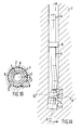
- a directional drilling assembly located in a borehole 1 in an underground formation 2.
- the assembly comprises a rotary drill bit 3 which is connected to the output shaft 4 of a downhole drilling motor, which motor is arranged at the lower end of a drill string 6.
- the motor is a Moineau motor which is driven by the drilling fluid flowing through the drill string 6.
- the motor housing 5 has a tilted shape in order to orient the output shaft 4 and bit 3 at a predetermined tilt angle ⁇ relative to the longitudinal axis A of the borehole 1.
- the motor is provided with a lowermost stabilizer 7 and a second stabilizer 8 which stabilize the assembly in a substantially centralized position in the borehole 1.
- the lowermost stabilizer 7 is mounted on the output shaft 4 and the second stabilizer 8 is mounted on the motor housing 5.
- the stabilizers 7 and 8 are bladed stablizers and as can be seen in Fig. 1B the lowermost stabilizer 7 is mounted concentrically around the hollow output shaft 4.
- the arrangement of the lowermost stabilizer 7 on the output shaft 4 has the advantage that the stabilizer 7 is rotated continuously during drilling so that any sticking tendency of the blades 8 of the stabilizer 7 against the boreholewall 9 is suppressed.
- the output shaft 4 is continuously actuated by the flow of drilling fluid through the motor to rotate relative to the motor housing 5. If by not rotating the drill string 6 the motor housing is held non-rotating the bit 3 will deepen the hole 1 in a deviated direction corresponding to the orientation of the central axis C of the output shaft 4.
- the central axis C of the output shaft 4 will make an orbital movement relative to the longitudinal borehole axis A which causes the bit 3 to make a gyrating movement in the hole 1 and to deepen the hole in the direction of the longitudinal axis A.
- straight and deviated borehole sections can be drilled at will by either rotating or not rotating the motor housing 5 during drilling.
- the arrangement according to the invention of the lowermost stabilizer 7 on or below the output shaft 4 has the principal advantage that this stabilizer is rotated continuously relative to the boreholewall, both during straight or deviated hole drilling.
- the continuous rotation of the lowermost stabalizer 7 ensures that the frictional forces F, which are generated as a result of the lateral forces L, are predominantly tangential and therefore absorbed as motor torque, rather than by an increase in longitudinal friction. In this manner any sticking tendency of the stabilizer 7 to the borehole wall is eliminated.
- a further advantage of the arrangement according to the invention of the lowermost stabilizer 7 on or below the output shaft 4 is that the stabilizer 7 is located close to the bit 3 which is useful for an optimum steering stability.
- the lowermost stabilizer 7 may be undersized in order to stabilize the bit in a substantially centralized position in the borehole 1.
- the second stabilizer 8 may be undersized as well and be mounted on the drillstring 6 above the motor housing 5.
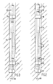
- Fig. 2 shows an embodiment of the present invention wherein the housing 11 of a downhole motor carrying a lowermost stabilizer 12 below its output shaft 13 is secured to the housing 14 of a second motor having a shaft 15 which is screwed to the lower end of a drill string 16.
- the housings 11, 14 of the twin motor arrangement thus provided can be held stationary in the borehole by inducing said second motor to rotate at the same speed as the drill string 16 above the motors but in an opposite direction.
- the second motor is a positive dispacement motor such as a Moineau motor.
- the speed of rotation of such a hydraulically driven motor can be accurately regulated by pumping a selected flow of drilling fluid through the drill string 16.
- a by-pass valve (not shown) may be located in said second motor which valve is opened during a selected period of time if survey instruments (e.g. gravitometers, magnetometers or gyroscopes) carried by the motor housings 11, 14 indicate that the housings are not oriented at a desired rotational orientation in the borehole.
- survey instruments e.g. gravitometers, magnetometers or gyroscopes
- the second stabilizer 18 which is mounted on the housing 14 of the second motor is rotated only during straighthole drilling, whereas the lowermost stabilizer 12 and the drill string 16 are rotated continuously both during deviated- and straighthole drilling. In this manner not only sticking of said lowermost stabilizer 17 is suppressed but also sticking to the borehole wall of the drill string 16 and any stabilizers (not shown) mounted thereon.
- the sticking forces exerted on the second stabilizer 18 stabilize the orientation of the dual motor housing 11, 14 during deviated drilling.
- the second stabilizer may be located such that it is rotated continuously during drilling.
- this is accomplished by mounting the second stabilizer 21 near the lower end of a drill string 22 carrying a twin motor assembly 23.
- the construction and operation of the twin motor assembly 23 is similar to those of the twin motor assembly shown in Fig. 2 apart from the arrangement of the second stabilizer 21 on the drill string instead of on the motor housings.
- the configuration shown in Fig. 3 has the advantage that the assembly comprises only continuously rotating components which are in contact with the borehole wall.
- the configuration of Fig. 3 is therefore particularly attractive for drilling sharply curved and highly deviated or horizontal holes. In such holes large contact forces may exist along the length of the drill string between the outer surface of the string and the borehole wall.
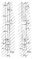
- Fig. 4 shows another embodiment of the present invention wherein the lowermost stabilizer 30 is mounted below the output shaft 31 of a downhole motor which carries on the housing 32 thereof an eccentric second stabilizer 33.
- the eccentricity E of the second stabilizer 33 is selected such that a drill bit 34 carried by the output shaft 31 is oriented at a predetermined tilt angle ⁇ relative to the longitudinal borehole axis A.
- the motor housing 32 is connected to the lower end of a drill string 35, which string is rotated during straighthole drilling and held stationary during deviated hole drilling in the same manner as the string disclosed in Fig. 1A is operated during drilling.
- the only difference between the drilling assemblies of Figures 1A and 4 is the arrangement of an eccentric second stabilizer 33 to orient the bit at a tilt angle ⁇ instead of accomplishing this by a concentric second stabilizer which is mounted on a tilted motor housing.
- Fig. 5 shows an embodiment of the present invention wherein a lowermost stabilizer 40 is mounted below an output shaft 41 of a twin motor assembly which carries an eccentric second stabilizer 42.
- Said second stabilizer 42 is mounted on the housing 43 of the upper motor of the assembly, which motor has a shaft 44 that is secured to the lower end of a rotary drill string 45.
- the eccentricity E of the second stabilizer 42 is selected such that a bit 4 carried by the output shaft 41 is oriented at a predetermined tilt angle ⁇ in the borehole 47.
- the operation of the assembly shown in Fig. 5 is similar to the operation of the assembly shown in Fig. 2.
- the housings 43, 48 are held non-rotating in the hole by rotating them in an opposite direction, at the same speed, relative to the drill string 45, whereas during straight hole drilling the housings 43, 48 are rotated relative to the drill string 45 at a speed different from the speed of rotation of the string.
- the lowermost stabilizer 40 and any further stabilizers (not shown) mounted on the drill string 45 are continuously rotated both during deviated and straight hole drilling so that any sticking tendency of these stabilizers to the boreholewall is suppressed.
- the motors of the twin motor assembly detailed above may be identical to each other so as to provide a "hydraulic shaft" between the drill string 45, and bit 46.
- the motors may also be of a different size or construction.
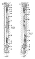
- the assembly shown in Fig. 6 comprises a Moineau motor having a housing 50 on which an eccentric second stabilizer 51 is mounted in order to orient a drill bit 52 carried by an output shaft 53 of the motor at a predetermined tilt angle ⁇ in the borehole.
- the assembly is further stabilized in the borehole by a lowermost stabilizer 54 mounted on the output shaft 53 and by a third stabilizer 55 which is mounted near the lower end of the drill string 56 above the motor.
- the motor comprises a rotor 57 which is connected to the output shaft 53 by a universal joint 58 and to the lower end of the drill string 56 by a second universal joint 59 and a second shaft 60.
- the rotor 57 forms a "flexible shaft" between the drill string 56 and drill bit 52, so that the drill bit 52 always rotates at the same speed as the drill string 56.
- the housing 50 is guided relative to the shafts 53 and 60 by two bearing units 61 and 62, respectively.
- the drill string 56 is continuously rotated and drilling fluid which is pumped via the string 56, the hollow second shaft 60 and radial fluid inlet ports 63 into the motor actuates the motor housing 50 to rotate in an opposite direction relative to the drill string 56.
- the housing 50 operates as a "bent sleeve" which rotates about the flexible shaft formed by the rotor 57 and two shafts 53, 60.
- the speed of rotation of the housing 50 relative to the rotor 57 is regulated by pumping a selected flow of drilling fluid via the drill string 56 into the motor.
- the housing 50 will be held in a stationary position in the borehole if it rotates in said opposite direction at the same speed as the drill string 56, whereas the housing 50 will rotate inside the borehole if it rotates at a speed different from the speed of rotation of the drill string 56.
- the housing 50 can either be held stationary in the borehole thereby enabling the bit to deepen the hole in a deviated direction or be rotated thereby inducing the bit to describe a gyrating motion and to deepen the hole in a straight direction.
- drilling of straight and deviated borehole sections can be accomplished by adjusting the ratio between the speed of drill string rotation and the amount of drilling fluid pumped through the string.
- the flow through the motor can be controlled by a bypass valve, which is controlled by e.g. gravitational, magnetic or gyroscopic sensors.
- the bypass flow may be routed via the annulus or via inside of a hollow rotor, or by a bypass which is parralel to the motor.
- the way of operation of the Moineau motor shown in Fig. 7 is similar to that of the motor shown in Fig. 6.
- the motor shown in Fig. 7 comprises a tilted housing 70 and a rotor 69 which is connected to an output shaft 71 and a second shaft 72 by a pair of universal joints 73, 74, respectively.
- the output shaft 71 is connected to a tubular section 75 which carries a drill bit 76 and the second shaft 72 is connected to the lower end of a drill string 77.
- the housing 70 is guided relative to the two shafts 71, 72 by two bearing units 78, 79, respectively, and the assembly is stabilized in the borehole by a lowermost stabilizer 80 mounted on said tubular section 75 below the output shaft 71 and a second stabilizer 81 mounted at the lower end of the drill string 77.
- the stabilizers 80, 81 stabilize the assembly in such a manner in the borehole that the drill bit 76 is oriented at a predetermined tilt angel ⁇ in the borehole.
- the rotor 69, universal joints 73, 74, shafts 71, 72 and tubular section 75 provide a "flexible shaft" between the drill string 77 and drill bit 76.
- the drill string 77 is continuously rotated whereas the housing 70 is rotated in an opposite direction either at the same or at a different speed so as to drill either deviated or straight borehole sections.
- Suitable motors are electric motors or hydraulic motors such as turbines, vane motors, roller vane motors and Moineau motors. It is preferred to use Moineau motors in view of their impassiveness for misalignment of the output shaft relative to the other motorparts, and the direct proportionallity of output shaft speed to flow rate.
- any suitable type of stabilizer may be used in the drilling assembly according to the invention.
- Particularly suitable stabilizers are bladed stabilizers provided with helical or straight blades.
- the lowermost stabilizer in the assembly according to the invention may be mounted on the output shaft of the drilling motor assembly, or on a drill bit carried by said shaft, or on a tubular element mounted between the output shaft and bit. If the lowermost stabilizer is mounted on the drill bit the stabilizer blades may be mounted above, between, or be formed by wings which carry the cutting elements of the bit and protrude in lateral direction away from the bit body. If, on the other hand, it is desired to locate the lowermost stabilizer at a distance above the bit, the stabilizer may be secured to the upper end of the output shaft and surround the lower part of the motorhousing.
Abstract
Description
- The invention relates to an assembly for directional drilling of boreholes in subsurface formations.
- During drilling of boreholes in subsurface formations it may be necessary to vary or adjust the direction of drilling from time to time. Various directional drilling tools are known in the art which are able to steer the bit in a desired direction.
- European patent specifications No. 0085444 and 0109699 disclose directional drilling tools which comprise a downhole motor provided with stabilizer means that stabilize the motor housing in such a manner in the hole that the bit driven by the motor has a tilted orientation in the hole. The steering capability of these motors is based on the fact that if the drill string carrying the motor housing is kept non-rotating during drilling the bit will deepen the hole in a deviated direction, whereas if the drill string carrying said housing is rotated during drilling the resulting gyrating movement of the bit causes the bit to deepen the hole in a straight direction. Hence, the drilling assemblies known from these patents are able to drill alternately straight and deviated borehole sections by alternately rotating and not-rotating the drill string carrying the motor.
- Field experience with the drilling assemblies known from the above patents has proved that these assemblies are very suitable and cost effective directional drilling tools which are able to continuously steer the bit during drilling in an accurate manner. Detailed examination of the path and shape of boreholes that have been drilled with these assemblies revealed however that during drilling of deviated hole sections in some formations the lateral forces exerted to the stabilizers may cause high friction forces between the blades of in particular the lowermost stabilizer and the boreholewall. It was found that this sticking of the stabilizer blades to the borehole wall resulted in a decrease in drilling progress during drilling of deviated hole sections.
- The present invention aims to provide a directional drilling assembly which is able to achieve a high drilling progress even during drilling of deviated hole sections.
- The drilling assembly according to the invention thereto comprises a downhole drilling motor and stabilizing means for stabilizing the assembly in a borehole such that in use an output shaft of the motor has a tilted orientation in the borehole, wherein said stabilizing means comprise a lowermost stabilizer which is secured to said output shaft.
- Said lowermost stabilizer may be mounted on said output shaft itself, or on a drill bit driven by the shaft, or on a tubular element mounted above or below the shaft. The arrangement according to the invention of a lowermost stabilizer on or below the output shaft instead of mounting said stabilizer on the motor housing as known from the above-mentioned patents has the principal advantage that the lowermost stabilizer rotates even during deviated drilling when the motor housing is kept stationary. In this manner the sticking tendency of the lowermost stabilizer is eliminated even if high lateral loads are exerted to said stabilizer as may happen in highly deviated boreholes. A further advantage of the arrangement according to the invention is that the lowermost stabilizer is located close to the bit which is useful for stable steering of the bit.
- The drilling assembly may be stabilized further up the hole by one or more other stabilizers. These other stabilizers may be mounted on the motor housing and/or on drill string sections located above the motor housing.
- In highly deviated or horizontal boreholes it may be desired to mount also these second and further stabilizers in such a manner on the drilling assembly that they rotate continuously even during drilling of deviated hole sections so as to avoid any sticking tendency of these stabilizers. This may be achieved in accordance with a preferred embodiment of the present invention by mounting the second and further stabilizers on a drill string section above the motor housing and by arranging a second downhole motor between said other motor and string section, which second motor has a housing which is connected to the housing of said other motor, and a shaft which is connected to said drill string section.
- During deviated drilling the interconnected housings of the twin motor assembly thus provided can be kept non-rotating in a desired orientation in the borehole by rotating the upper motor in an opposite direction but at the same speed as the drill string carrying the motors. During straight hole drilling the upper motor may be rotated at a speed different from the speed of rotation of the drill string.
- The invention will now be explained in more detail with reference to the accompanying drawings, in which:
- Figure 1A shows a directional drilling assembly according to the invention comprising a drilling motor of which the housing has a tilted shape,
- Figure 1B is a cross-section of the assembly of Figure 1, seen along line II-II,
- Figure 2 shows an embodiment of the invention wherein a concentric second stabilizer is mounted on a housing of a twin drilling motor assembly,
- Figure 3 shows an embodiment of the invention wherein a concentric second stabilizer is mounted on a drill string section above a twin drilling motor assembly,
- Figure 4 shows an embodiment of the invention wherein an eccentric second stabilizer is mounted on the motor housing,
- Figure 5 shows an embodiment of the invention wherein an eccentric second stabilizer is mounted on a housing of a twin drilling motor assembly,
- Figure 6 shows an embodiment of the invention wherein an eccentric stabilizer is mounted on the housing of a motor having a rotor which is connected via a second shaft to the lower end of a drillstring, and
- Figure 7 shows yet another embodiment of the invention wherein a second stabilizer is mounted on a drillstring which is connected via a second shaft to the rotor of a motor having a tilted housing.
- In Fig. 1A there is shown a directional drilling assembly according to the invention located in a
borehole 1 in anunderground formation 2. The assembly comprises a rotary drill bit 3 which is connected to the output shaft 4 of a downhole drilling motor, which motor is arranged at the lower end of a drill string 6. The motor is a Moineau motor which is driven by the drilling fluid flowing through the drill string 6. The motor housing 5 has a tilted shape in order to orient the output shaft 4 and bit 3 at a predetermined tilt angle α relative to the longitudinal axis A of theborehole 1. The motor is provided with a lowermost stabilizer 7 and asecond stabilizer 8 which stabilize the assembly in a substantially centralized position in theborehole 1. - The lowermost stabilizer 7 is mounted on the output shaft 4 and the
second stabilizer 8 is mounted on the motor housing 5. Thestabilizers 7 and 8 are bladed stablizers and as can be seen in Fig. 1B the lowermost stabilizer 7 is mounted concentrically around the hollow output shaft 4. - As will be explained hereinbelow the arrangement of the lowermost stabilizer 7 on the output shaft 4 has the advantage that the stabilizer 7 is rotated continuously during drilling so that any sticking tendency of the
blades 8 of the stabilizer 7 against the boreholewall 9 is suppressed. During drilling operations the output shaft 4 is continuously actuated by the flow of drilling fluid through the motor to rotate relative to the motor housing 5. If by not rotating the drill string 6 the motor housing is held non-rotating the bit 3 will deepen thehole 1 in a deviated direction corresponding to the orientation of the central axis C of the output shaft 4. If the drill string 6 and motor housing 5 are rotated during drilling the central axis C of the output shaft 4 will make an orbital movement relative to the longitudinal borehole axis A which causes the bit 3 to make a gyrating movement in thehole 1 and to deepen the hole in the direction of the longitudinal axis A. Hence straight and deviated borehole sections can be drilled at will by either rotating or not rotating the motor housing 5 during drilling. The arrangement according to the invention of the lowermost stabilizer 7 on or below the output shaft 4 has the principal advantage that this stabilizer is rotated continuously relative to the boreholewall, both during straight or deviated hole drilling. - As schematically shown in Fig. 1B the continuous rotation of the lowermost stabalizer 7 ensures that the frictional forces F, which are generated as a result of the lateral forces L, are predominantly tangential and therefore absorbed as motor torque, rather than by an increase in longitudinal friction. In this manner any sticking tendency of the stabilizer 7 to the borehole wall is eliminated. A further advantage of the arrangement according to the invention of the lowermost stabilizer 7 on or below the output shaft 4 is that the stabilizer 7 is located close to the bit 3 which is useful for an optimum steering stability. If desired, the lowermost stabilizer 7 may be undersized in order to stabilize the bit in a substantially centralized position in the
borehole 1. If desired, thesecond stabilizer 8 may be undersized as well and be mounted on the drillstring 6 above the motor housing 5. - Fig. 2 shows an embodiment of the present invention wherein the housing 11 of a downhole motor carrying a
lowermost stabilizer 12 below itsoutput shaft 13 is secured to thehousing 14 of a second motor having ashaft 15 which is screwed to the lower end of adrill string 16. Thehousings 11, 14 of the twin motor arrangement thus provided can be held stationary in the borehole by inducing said second motor to rotate at the same speed as thedrill string 16 above the motors but in an opposite direction. In the example shown the second motor is a positive dispacement motor such as a Moineau motor. The speed of rotation of such a hydraulically driven motor can be accurately regulated by pumping a selected flow of drilling fluid through thedrill string 16. In order to keep the motor housings stationary in a desired orientation a by-pass valve (not shown) may be located in said second motor which valve is opened during a selected period of time if survey instruments (e.g. gravitometers, magnetometers or gyroscopes) carried by themotor housings 11, 14 indicate that the housings are not oriented at a desired rotational orientation in the borehole. - During straighthole drilling, when it is desired that the
motor housings 11, 14 rotate inside the borehole so as to induce thebit 17 to describe a gyrating movement the flow of drilling fluid through thedrill string 16 is regulated such that themotor housings 11, 14 rotate at a different speed than thedrill string 16 itself. - During operation of the assembly shown in Fig. 2 the
second stabilizer 18 which is mounted on thehousing 14 of the second motor is rotated only during straighthole drilling, whereas thelowermost stabilizer 12 and thedrill string 16 are rotated continuously both during deviated- and straighthole drilling. In this manner not only sticking of saidlowermost stabilizer 17 is suppressed but also sticking to the borehole wall of thedrill string 16 and any stabilizers (not shown) mounted thereon. The sticking forces exerted on thesecond stabilizer 18 stabilize the orientation of thedual motor housing 11, 14 during deviated drilling. - As illustrated in Fig. 3 also the second stabilizer may be located such that it is rotated continuously during drilling. In the assembly of Fig. 3 this is accomplished by mounting the
second stabilizer 21 near the lower end of adrill string 22 carrying atwin motor assembly 23. The construction and operation of thetwin motor assembly 23 is similar to those of the twin motor assembly shown in Fig. 2 apart from the arrangement of thesecond stabilizer 21 on the drill string instead of on the motor housings. The configuration shown in Fig. 3 has the advantage that the assembly comprises only continuously rotating components which are in contact with the borehole wall. The configuration of Fig. 3 is therefore particularly attractive for drilling sharply curved and highly deviated or horizontal holes. In such holes large contact forces may exist along the length of the drill string between the outer surface of the string and the borehole wall. By continuously rotating thelowermost stabilizer 24, thesecond stabilizer 21 and any other stabilizer carried by thestring 22 the tendency of sticking of any of these stabilizers to the boreholewall is suppressed so that a smooth drilling progress is ensured. - Fig. 4 shows another embodiment of the present invention wherein the
lowermost stabilizer 30 is mounted below theoutput shaft 31 of a downhole motor which carries on thehousing 32 thereof an eccentricsecond stabilizer 33. The eccentricity E of thesecond stabilizer 33 is selected such that adrill bit 34 carried by theoutput shaft 31 is oriented at a predetermined tilt angle α relative to the longitudinal borehole axis A. Themotor housing 32 is connected to the lower end of adrill string 35, which string is rotated during straighthole drilling and held stationary during deviated hole drilling in the same manner as the string disclosed in Fig. 1A is operated during drilling. The only difference between the drilling assemblies of Figures 1A and 4 is the arrangement of an eccentricsecond stabilizer 33 to orient the bit at a tilt angle α instead of accomplishing this by a concentric second stabilizer which is mounted on a tilted motor housing. - Fig. 5 shows an embodiment of the present invention wherein a
lowermost stabilizer 40 is mounted below an output shaft 41 of a twin motor assembly which carries an eccentricsecond stabilizer 42. Saidsecond stabilizer 42 is mounted on thehousing 43 of the upper motor of the assembly, which motor has ashaft 44 that is secured to the lower end of arotary drill string 45. The eccentricity E of thesecond stabilizer 42 is selected such that a bit 4 carried by the output shaft 41 is oriented at a predetermined tilt angle α in the borehole 47. - The operation of the assembly shown in Fig. 5 is similar to the operation of the assembly shown in Fig. 2. During deviated hole drilling the
housings drill string 45, whereas during straight hole drilling thehousings drill string 45 at a speed different from the speed of rotation of the string. In this way it is accomplished that thelowermost stabilizer 40 and any further stabilizers (not shown) mounted on thedrill string 45 are continuously rotated both during deviated and straight hole drilling so that any sticking tendency of these stabilizers to the boreholewall is suppressed. - The motors of the twin motor assembly detailed above may be identical to each other so as to provide a "hydraulic shaft" between the
drill string 45, andbit 46. However, the motors may also be of a different size or construction. - Instead of using a twin motor assembly to keep the output shaft in a stationary orientation in the borehole while rotating the drill string this may be accomplished by a single motor as well. In the drilling assemblies shown in Fig. 6 and 7 this is accomplished by providing a single motor with a rotor which is connected both to the drill bit and to the drill string above the motor.
- The assembly shown in Fig. 6 comprises a Moineau motor having a
housing 50 on which an eccentricsecond stabilizer 51 is mounted in order to orient adrill bit 52 carried by anoutput shaft 53 of the motor at a predetermined tilt angle α in the borehole. The assembly is further stabilized in the borehole by alowermost stabilizer 54 mounted on theoutput shaft 53 and by athird stabilizer 55 which is mounted near the lower end of thedrill string 56 above the motor. The motor comprises arotor 57 which is connected to theoutput shaft 53 by auniversal joint 58 and to the lower end of thedrill string 56 by a seconduniversal joint 59 and asecond shaft 60. Thus therotor 57 forms a "flexible shaft" between thedrill string 56 anddrill bit 52, so that thedrill bit 52 always rotates at the same speed as thedrill string 56. - The
housing 50 is guided relative to theshafts units drill string 56 is continuously rotated and drilling fluid which is pumped via thestring 56, the hollowsecond shaft 60 and radialfluid inlet ports 63 into the motor actuates themotor housing 50 to rotate in an opposite direction relative to thedrill string 56. Thus thehousing 50 operates as a "bent sleeve" which rotates about the flexible shaft formed by therotor 57 and twoshafts housing 50 relative to therotor 57 is regulated by pumping a selected flow of drilling fluid via thedrill string 56 into the motor. Thehousing 50 will be held in a stationary position in the borehole if it rotates in said opposite direction at the same speed as thedrill string 56, whereas thehousing 50 will rotate inside the borehole if it rotates at a speed different from the speed of rotation of thedrill string 56. - Thus, by varying the flow of drilling fluid through the assembly the
housing 50 can either be held stationary in the borehole thereby enabling the bit to deepen the hole in a deviated direction or be rotated thereby inducing the bit to describe a gyrating motion and to deepen the hole in a straight direction. In this manner drilling of straight and deviated borehole sections can be accomplished by adjusting the ratio between the speed of drill string rotation and the amount of drilling fluid pumped through the string. Alternatively the flow through the motor can be controlled by a bypass valve, which is controlled by e.g. gravitational, magnetic or gyroscopic sensors. The bypass flow may be routed via the annulus or via inside of a hollow rotor, or by a bypass which is parralel to the motor. - Since in the assembly shown in Fig. 6 the
lowermost stabilizer 54 andthird stabilizer 55 are continuously rotated during drilling any sticking tendency of these stabilizers to the borehole wall is eliminated. - The way of operation of the Moineau motor shown in Fig. 7 is similar to that of the motor shown in Fig. 6. The motor shown in Fig. 7 comprises a tilted
housing 70 and arotor 69 which is connected to anoutput shaft 71 and asecond shaft 72 by a pair ofuniversal joints output shaft 71 is connected to atubular section 75 which carries adrill bit 76 and thesecond shaft 72 is connected to the lower end of adrill string 77. - The
housing 70 is guided relative to the twoshafts units lowermost stabilizer 80 mounted on saidtubular section 75 below theoutput shaft 71 and asecond stabilizer 81 mounted at the lower end of thedrill string 77. Thestabilizers drill bit 76 is oriented at a predetermined tilt angel α in the borehole. - The
rotor 69,universal joints shafts tubular section 75 provide a "flexible shaft" between thedrill string 77 anddrill bit 76. - During drilling the
drill string 77 is continuously rotated whereas thehousing 70 is rotated in an opposite direction either at the same or at a different speed so as to drill either deviated or straight borehole sections. - Since the
lowermost stabilizer 80 andsecond stabilizer 81 are continuously rotated during drilling any sticking tendency of these stabilizers to the boreholewall is eliminated. - Various types of downhole motors may be utilized in the assembly according to the invention. Suitable motors are electric motors or hydraulic motors such as turbines, vane motors, roller vane motors and Moineau motors. It is preferred to use Moineau motors in view of their impassiveness for misalignment of the output shaft relative to the other motorparts, and the direct proportionallity of output shaft speed to flow rate.
- It will be understood that any suitable type of stabilizer may be used in the drilling assembly according to the invention. Particularly suitable stabilizers are bladed stabilizers provided with helical or straight blades.
- It will further be understood that the lowermost stabilizer in the assembly according to the invention may be mounted on the output shaft of the drilling motor assembly, or on a drill bit carried by said shaft, or on a tubular element mounted between the output shaft and bit. If the lowermost stabilizer is mounted on the drill bit the stabilizer blades may be mounted above, between, or be formed by wings which carry the cutting elements of the bit and protrude in lateral direction away from the bit body. If, on the other hand, it is desired to locate the lowermost stabilizer at a distance above the bit, the stabilizer may be secured to the upper end of the output shaft and surround the lower part of the motorhousing.
Claims (12)
- A drilling assembly for directional drilling of boreholes in subsurface formations, the assembly comprising a downhole drilling motor, said motor having an output shaft (4) which is suitable to drive a rotary drill bit (3) and a motor housing (5) which is suitable to be arranged at the lower end of a drill string, and stabilizing means for stabilizing the assembly in a borehole such that in use the output shaft has a tilted orientation in the borehole, characterized in that said stabilizing means include a lowermost stabilizer (7) which is secured to said output shaft.
- The assembly of claim 1, wherein said lowermost stabilizer is mounted concentrically on said output shaft.
- The assembly of claim 1, wherein said lowermost stabilizer is mounted on a tubular element which is connected to the lower end of said shaft.
- The assembly of claim 1, wherein said lowermost stabilizer is mounted on the shank of a rotary drill bit carried by said shaft.
- The assembly of claim 1, wherein said stabilizing means further comprise a second stabilizer (8) which is mounted on the motor housing.
- The assembly of claim 5, wherein said second stabilizer is mounted eccentrically on said motor housing.
- The assembly of claim 5, wherein said second stabilizer is mounted concentrically on said motor housing.
- The assembly of claim 7, wherein said motor housing has a tilted shape in an area between said lowermost and second stabilizer.
- The assembly of claim 1, wherein the stabilizing means comprise a second stabilizer which is mounted on a drill string section above the motor housing.
- The assembly of claim 9, wherein between said drill string section and motor housing a second downhole motor is arranged, said second motor having a housing which is connected to the housing of said other motor and a shaft which is connected to said drill string section.
- The assembly of claim 1, wherein said motor comprises a rotor which is connected to the output shaft and via a second shaft to the drill string above the motor.
- The assembly of any one of claims 1-11, wherein each downhole motor is a hydraulically driven motor of the Moineau type.
Priority Applications (1)
| Application Number | Priority Date | Filing Date | Title |
|---|---|---|---|
| AT88200654T ATE82797T1 (en) | 1987-04-13 | 1988-04-06 | DEVICE FOR DIRECTIONAL DRILLING OF BOREHOLES. |
Applications Claiming Priority (2)
| Application Number | Priority Date | Filing Date | Title |
|---|---|---|---|
| GB8708791 | 1987-04-13 | ||
| GB878708791A GB8708791D0 (en) | 1987-04-13 | 1987-04-13 | Assembly for directional drilling of boreholes |
Publications (3)
| Publication Number | Publication Date |
|---|---|
| EP0287155A2 EP0287155A2 (en) | 1988-10-19 |
| EP0287155A3 EP0287155A3 (en) | 1989-11-15 |
| EP0287155B1 true EP0287155B1 (en) | 1992-11-25 |
Family
ID=10615723
Family Applications (1)
| Application Number | Title | Priority Date | Filing Date |
|---|---|---|---|
| EP88200654A Expired - Lifetime EP0287155B1 (en) | 1987-04-13 | 1988-04-06 | Assembly for directional drilling of boreholes |
Country Status (7)
| Country | Link |
|---|---|
| US (1) | US4880066A (en) |
| EP (1) | EP0287155B1 (en) |
| AT (1) | ATE82797T1 (en) |
| AU (1) | AU599474B2 (en) |
| DE (1) | DE3876127T2 (en) |
| GB (1) | GB8708791D0 (en) |
| NO (1) | NO881425L (en) |
Families Citing this family (39)
| Publication number | Priority date | Publication date | Assignee | Title |
|---|---|---|---|---|
| US5050692A (en) * | 1987-08-07 | 1991-09-24 | Baker Hughes Incorporated | Method for directional drilling of subterranean wells |
| DE3804493A1 (en) * | 1988-02-12 | 1989-08-24 | Eastman Christensen Co | DEVICE FOR SELECTING STRAIGHT OR DIRECTIONAL DRILLING IN UNDERGROUND STONE INFORMATION |
| FR2641315B1 (en) * | 1988-12-30 | 1996-05-24 | Inst Francais Du Petrole | DRILLING LINING WITH CONTROLLED PATHWAY COMPRISING A VARIABLE GEOMETRIC STABILIZER AND USE OF SAID LINING |
| US4995465A (en) * | 1989-11-27 | 1991-02-26 | Conoco Inc. | Rotary drillstring guidance by feedrate oscillation |
| US5022471A (en) * | 1990-01-08 | 1991-06-11 | Maurer Engineering, Inc. | Deviated wellbore drilling system and apparatus |
| US5139094A (en) * | 1991-02-01 | 1992-08-18 | Anadrill, Inc. | Directional drilling methods and apparatus |
| US5117927A (en) * | 1991-02-01 | 1992-06-02 | Anadrill | Downhole adjustable bent assemblies |
| FR2678678A1 (en) * | 1991-07-04 | 1993-01-08 | Smf Int | DEVICE FOR ADJUSTING THE AZIMUT OF THE TRAJECTORY OF A DRILLING TOOL IN ROTARY MODE. |
| GB9202163D0 (en) * | 1992-01-31 | 1992-03-18 | Neyrfor Weir Ltd | Stabilisation devices for drill motors |
| SE470177B (en) * | 1992-03-23 | 1993-11-29 | Radi Medical Systems | Device for punching in hard tissue and puncture needle |
| WO1993024728A1 (en) * | 1992-05-27 | 1993-12-09 | Astec Developments Limited | Downhole tools |
| US5325714A (en) * | 1993-05-12 | 1994-07-05 | Baker Hughes Incorporated | Steerable motor system with integrated formation evaluation logging capacity |
| US5673765A (en) * | 1993-10-01 | 1997-10-07 | Wattenburg; Willard H. | Downhole drilling subassembly and method for same |
| US5445230A (en) * | 1993-10-01 | 1995-08-29 | Wattenburg; Willard H. | Downhole drilling subassembly and method for same |
| US5542482A (en) * | 1994-11-01 | 1996-08-06 | Schlumberger Technology Corporation | Articulated directional drilling motor assembly |
| US5727641A (en) * | 1994-11-01 | 1998-03-17 | Schlumberger Technology Corporation | Articulated directional drilling motor assembly |
| GB9610382D0 (en) * | 1996-05-17 | 1996-07-24 | Anderson Charles A | Drilling apparatus |
| US6607044B1 (en) | 1997-10-27 | 2003-08-19 | Halliburton Energy Services, Inc. | Three dimensional steerable system and method for steering bit to drill borehole |
| US6920944B2 (en) * | 2000-06-27 | 2005-07-26 | Halliburton Energy Services, Inc. | Apparatus and method for drilling and reaming a borehole |
| US6213226B1 (en) | 1997-12-04 | 2001-04-10 | Halliburton Energy Services, Inc. | Directional drilling assembly and method |
| US6269892B1 (en) | 1998-12-21 | 2001-08-07 | Dresser Industries, Inc. | Steerable drilling system and method |
| US6446737B1 (en) * | 1999-09-14 | 2002-09-10 | Deep Vision Llc | Apparatus and method for rotating a portion of a drill string |
| US6422328B1 (en) * | 1999-10-27 | 2002-07-23 | Baker Hughes Incorporated | Dual cutting mill |
| EP1244865A1 (en) * | 2000-01-06 | 2002-10-02 | Ultidrill B.V. | Long gauge roller vane drilling motor |
| US7156171B2 (en) * | 2000-09-06 | 2007-01-02 | Casetech International, Inc. | Dual diameter and rotating centralizer/sub |
| US7182131B2 (en) * | 2000-09-06 | 2007-02-27 | Casetech International, Inc. | Dual diameter and rotating centralizer/sub and method |
| US6484803B1 (en) * | 2000-09-06 | 2002-11-26 | Casetech International, Inc. | Dual diameter centralizer/sub and method |
| AU2003257476A1 (en) * | 2002-07-26 | 2004-02-23 | Wirth Maschinen- Und Bohrgeratefabrik Gmbh | Device for advancing drillings in the ground |
| US7243739B2 (en) * | 2004-03-11 | 2007-07-17 | Rankin Iii Robert E | Coiled tubing directional drilling apparatus |
| US7703551B2 (en) * | 2005-06-21 | 2010-04-27 | Bow River Tools And Services Ltd. | Fluid driven drilling motor and system |
| US7766098B2 (en) | 2007-08-31 | 2010-08-03 | Precision Energy Services, Inc. | Directional drilling control using modulated bit rotation |
| GB0811016D0 (en) | 2008-06-17 | 2008-07-23 | Smart Stabilizer Systems Ltd | Steering component and steering assembly |
| NO333280B1 (en) * | 2009-05-06 | 2013-04-29 | Norwegian Hard Rock Drilling As | Control device for rock drill. |
| KR20160039208A (en) * | 2013-08-05 | 2016-04-08 | 지오넥스 오와이 | Method for steering a direction of a drilling device drilling a hole into the ground |
| WO2015102599A1 (en) | 2013-12-31 | 2015-07-09 | Halliburton Energy Services, Inc. | Bend measurements of adjustable motor assemblies using magnetometers |
| CA2931801C (en) | 2013-12-31 | 2020-07-21 | Halliburton Energy Services, Inc. | Bend measurements of adjustable motor assemblies using inclinometers |
| US9816369B2 (en) | 2013-12-31 | 2017-11-14 | Halliburton Energy Services, Inc. | Bend measurements of adjustable motor assemblies using strain gauges |
| CN108278081B (en) * | 2017-01-05 | 2020-05-22 | 通用电气公司 | Rotary steerable drilling system and method based on imbalance force measurement control |
| US11629555B2 (en) * | 2018-12-21 | 2023-04-18 | Halliburton Energy Services, Inc. | Drilling a borehole with a steering system using a modular cam arrangement |
Family Cites Families (17)
| Publication number | Priority date | Publication date | Assignee | Title |
|---|---|---|---|---|
| US2890859A (en) * | 1957-02-25 | 1959-06-16 | Eastware Oil Well Survey Compa | Turbine well drilling apparatus |
| US3561549A (en) * | 1968-06-07 | 1971-02-09 | Smith Ind International Inc | Slant drilling tools for oil wells |
| US3999901A (en) * | 1973-11-14 | 1976-12-28 | Smith International, Inc. | Progressive cavity transducer |
| US4011917A (en) * | 1974-08-19 | 1977-03-15 | Wladimir Tiraspolsky | Process and universal downhole motor for driving a tool |
| US4040495A (en) * | 1975-12-22 | 1977-08-09 | Smith International, Inc. | Drilling apparatus |
| FR2369412A1 (en) * | 1976-11-02 | 1978-05-26 | Alsthom Atlantique | Target boring along inclined vertical axis - using elbow and guides above cutter and below stabiliser |
| US4185704A (en) * | 1978-05-03 | 1980-01-29 | Maurer Engineering Inc. | Directional drilling apparatus |
| SU878895A1 (en) * | 1979-09-20 | 1981-11-07 | Печорский государственный научно-исследовательский и проектный институт нефтяной промышленности | Arrangement for drilling string for directional drilling |
| US4436168A (en) * | 1982-01-12 | 1984-03-13 | Dismukes Newton B | Thrust generator for boring tools |
| ATE15927T1 (en) * | 1982-02-02 | 1985-10-15 | Shell Int Research | METHOD AND DEVICE FOR CONTROLLING THE DIRECTION OF THE BOREHOLE. |
| ATE22961T1 (en) * | 1982-08-25 | 1986-11-15 | Shell Int Research | DOWNHOLE DRIVE AND DIRECTIONAL DRILLING METHOD. |
| US4492276A (en) * | 1982-11-17 | 1985-01-08 | Shell Oil Company | Down-hole drilling motor and method for directional drilling of boreholes |
| US4739842A (en) * | 1984-05-12 | 1988-04-26 | Eastman Christensen Company | Apparatus for optional straight or directional drilling underground formations |
| US4577701A (en) * | 1984-08-08 | 1986-03-25 | Mobil Oil Corporation | System of drilling deviated wellbores |
| EP0232421B1 (en) * | 1985-07-22 | 1991-11-13 | Vsesojuzny Nauchno-Issledovatelsky Institut Burovoi Tekhniki | Screw machine |
| US4667751A (en) * | 1985-10-11 | 1987-05-26 | Smith International, Inc. | System and method for controlled directional drilling |
| US4697651A (en) * | 1986-12-22 | 1987-10-06 | Mobil Oil Corporation | Method of drilling deviated wellbores |
-
1987
- 1987-04-13 GB GB878708791A patent/GB8708791D0/en active Pending
-
1988
- 1988-01-25 US US07/147,402 patent/US4880066A/en not_active Expired - Lifetime
- 1988-03-30 NO NO881425A patent/NO881425L/en unknown
- 1988-04-05 AU AU14175/88A patent/AU599474B2/en not_active Ceased
- 1988-04-06 DE DE8888200654T patent/DE3876127T2/en not_active Expired - Fee Related
- 1988-04-06 AT AT88200654T patent/ATE82797T1/en active
- 1988-04-06 EP EP88200654A patent/EP0287155B1/en not_active Expired - Lifetime
Also Published As
| Publication number | Publication date |
|---|---|
| EP0287155A2 (en) | 1988-10-19 |
| US4880066A (en) | 1989-11-14 |
| DE3876127T2 (en) | 1993-04-01 |
| NO881425D0 (en) | 1988-03-30 |
| EP0287155A3 (en) | 1989-11-15 |
| ATE82797T1 (en) | 1992-12-15 |
| NO881425L (en) | 1988-10-14 |
| GB8708791D0 (en) | 1987-05-20 |
| AU1417588A (en) | 1988-10-13 |
| DE3876127D1 (en) | 1993-01-07 |
| AU599474B2 (en) | 1990-07-19 |
Similar Documents
| Publication | Publication Date | Title |
|---|---|---|
| EP0287155B1 (en) | Assembly for directional drilling of boreholes | |
| US4492276A (en) | Down-hole drilling motor and method for directional drilling of boreholes | |
| AU2015255267B2 (en) | Method and apparatus for controlling downhole rotational rate of a drilling tool | |
| EP0677640B1 (en) | Improvements in or relating to steerable rotary drilling systems | |
| US4836301A (en) | Method and apparatus for directional drilling | |
| US5979570A (en) | Surface controlled wellbore directional steering tool | |
| EP0103913B1 (en) | Down-hole motor and method for directional drilling of boreholes | |
| US5050692A (en) | Method for directional drilling of subterranean wells | |
| US7004263B2 (en) | Directional casing drilling | |
| US6269892B1 (en) | Steerable drilling system and method | |
| US4817740A (en) | Apparatus for directional drilling of subterranean wells | |
| US6216802B1 (en) | Gravity oriented directional drilling apparatus and method | |
| US5060736A (en) | Steerable tool underreaming system | |
| US9963937B2 (en) | Method and apparatus for controlling downhole rotational rate of a drilling tool | |
| GB2343470A (en) | Eccentrically weighted drilling apparatus for deviated boreholes | |
| US20150090497A1 (en) | Directional Drilling Using Variable Bit Speed, Thrust, and Active Deflection | |
| GB2121453A (en) | Stabilizer/housing assembly and method for the directional drilling of boreholes | |
| US6883622B2 (en) | Method for drilling a wellbore using a bi-center drill bit | |
| AU766588B2 (en) | Actively controlled rotary steerable system and method for drilling wells | |
| GB2621111A (en) | A subassembly for a directional drilling system |
Legal Events
| Date | Code | Title | Description |
|---|---|---|---|
| PUAI | Public reference made under article 153(3) epc to a published international application that has entered the european phase |
Free format text: ORIGINAL CODE: 0009012 |
|
| AK | Designated contracting states |
Kind code of ref document: A2 Designated state(s): AT BE DE FR GB IT NL |
|
| PUAL | Search report despatched |
Free format text: ORIGINAL CODE: 0009013 |
|
| AK | Designated contracting states |
Kind code of ref document: A3 Designated state(s): AT BE DE FR GB IT NL |
|
| 17P | Request for examination filed |
Effective date: 19900320 |
|
| 17Q | First examination report despatched |
Effective date: 19910528 |
|
| GRAA | (expected) grant |
Free format text: ORIGINAL CODE: 0009210 |
|
| AK | Designated contracting states |
Kind code of ref document: B1 Designated state(s): AT BE DE FR GB IT NL |
|
| REF | Corresponds to: |
Ref document number: 82797 Country of ref document: AT Date of ref document: 19921215 Kind code of ref document: T |
|
| ITF | It: translation for a ep patent filed |
Owner name: JACOBACCI & PERANI S.P.A. |
|
| REF | Corresponds to: |
Ref document number: 3876127 Country of ref document: DE Date of ref document: 19930107 |
|
| ET | Fr: translation filed | ||
| PGFP | Annual fee paid to national office [announced via postgrant information from national office to epo] |
Ref country code: GB Payment date: 19930302 Year of fee payment: 6 Ref country code: FR Payment date: 19930302 Year of fee payment: 6 |
|
| PGFP | Annual fee paid to national office [announced via postgrant information from national office to epo] |
Ref country code: AT Payment date: 19930413 Year of fee payment: 6 |
|
| PGFP | Annual fee paid to national office [announced via postgrant information from national office to epo] |
Ref country code: NL Payment date: 19930430 Year of fee payment: 6 |
|
| PGFP | Annual fee paid to national office [announced via postgrant information from national office to epo] |
Ref country code: DE Payment date: 19930510 Year of fee payment: 6 Ref country code: BE Payment date: 19930510 Year of fee payment: 6 |
|
| PLBE | No opposition filed within time limit |
Free format text: ORIGINAL CODE: 0009261 |
|
| STAA | Information on the status of an ep patent application or granted ep patent |
Free format text: STATUS: NO OPPOSITION FILED WITHIN TIME LIMIT |
|
| 26N | No opposition filed | ||
| PG25 | Lapsed in a contracting state [announced via postgrant information from national office to epo] |
Ref country code: GB Effective date: 19940406 Ref country code: AT Effective date: 19940406 |
|
| PG25 | Lapsed in a contracting state [announced via postgrant information from national office to epo] |
Ref country code: BE Effective date: 19940430 |
|
| BERE | Be: lapsed |
Owner name: SHELL INTERNATIONALE RESEARCH MAATSCHAPPIJ B.V. Effective date: 19940430 |
|
| PG25 | Lapsed in a contracting state [announced via postgrant information from national office to epo] |
Ref country code: NL Effective date: 19941101 |
|
| GBPC | Gb: european patent ceased through non-payment of renewal fee |
Effective date: 19940406 |
|
| NLV4 | Nl: lapsed or anulled due to non-payment of the annual fee | ||
| PG25 | Lapsed in a contracting state [announced via postgrant information from national office to epo] |
Ref country code: FR Effective date: 19941229 |
|
| PG25 | Lapsed in a contracting state [announced via postgrant information from national office to epo] |
Ref country code: DE Effective date: 19950103 |
|
| REG | Reference to a national code |
Ref country code: FR Ref legal event code: ST |
|
| PG25 | Lapsed in a contracting state [announced via postgrant information from national office to epo] |
Ref country code: IT Free format text: LAPSE BECAUSE OF NON-PAYMENT OF DUE FEES;WARNING: LAPSES OF ITALIAN PATENTS WITH EFFECTIVE DATE BEFORE 2007 MAY HAVE OCCURRED AT ANY TIME BEFORE 2007. THE CORRECT EFFECTIVE DATE MAY BE DIFFERENT FROM THE ONE RECORDED. Effective date: 20050406 |