EP0286770A2 - Device for automatically centering discs with different diameters on the loading means of a disc player - Google Patents
Device for automatically centering discs with different diameters on the loading means of a disc player Download PDFInfo
- Publication number
- EP0286770A2 EP0286770A2 EP87870172A EP87870172A EP0286770A2 EP 0286770 A2 EP0286770 A2 EP 0286770A2 EP 87870172 A EP87870172 A EP 87870172A EP 87870172 A EP87870172 A EP 87870172A EP 0286770 A2 EP0286770 A2 EP 0286770A2
- Authority
- EP
- European Patent Office
- Prior art keywords
- movement
- disc
- supports
- axis
- drawer
- Prior art date
- Legal status (The legal status is an assumption and is not a legal conclusion. Google has not performed a legal analysis and makes no representation as to the accuracy of the status listed.)
- Granted
Links
Images


Classifications
-
- G—PHYSICS
- G11—INFORMATION STORAGE
- G11B—INFORMATION STORAGE BASED ON RELATIVE MOVEMENT BETWEEN RECORD CARRIER AND TRANSDUCER
- G11B17/00—Guiding record carriers not specifically of filamentary or web form, or of supports therefor
- G11B17/02—Details
- G11B17/022—Positioning or locking of single discs
- G11B17/028—Positioning or locking of single discs of discs rotating during transducing operation
-
- G—PHYSICS
- G11—INFORMATION STORAGE
- G11B—INFORMATION STORAGE BASED ON RELATIVE MOVEMENT BETWEEN RECORD CARRIER AND TRANSDUCER
- G11B17/00—Guiding record carriers not specifically of filamentary or web form, or of supports therefor
- G11B17/02—Details
- G11B17/04—Feeding or guiding single record carrier to or from transducer unit
- G11B17/05—Feeding or guiding single record carrier to or from transducer unit specially adapted for discs not contained within cartridges
- G11B17/053—Indirect insertion, i.e. with external loading means
- G11B17/056—Indirect insertion, i.e. with external loading means with sliding loading means
- G11B17/0565—Indirect insertion, i.e. with external loading means with sliding loading means adapted for discs of different sizes
Definitions
- the present device relates to disc player devices and more particularly to those where the positioning of the disc on the rotation means is carried out by means of a movable plate or "drawer", as is the case of many CD players (Compact Discs).
- This drawer formed in the front face of the device makes it possible, in the "out” position, to receive the disc, then by translation to transport the disc inside the device by bringing it above its means of rotation and finally to place it on the drive plate, the disc then being in its reproduction position.
- Friction devices have also been proposed, in particular by US Pat. No. 4,625,304, that is to say permanently active to center discs of different diameters and the operating mode of which is reversed at the end of travel for free the periphery of the disc, after centering, to allow free space rotation.
- Such devices are complicated (reversing movement at the end of the stroke), they prove to be unreliable over time because of the very fact that they use friction. Indeed, it wears down at each centering and all the more quickly when large diameter discs are used because they involve a significant slip of the friction.
- the object of the present invention is to remedy the aforementioned drawbacks by proposing a loading device by drawer automatically ensuring the centering of discs of different diameters only when necessary.
- a second object of the invention is to present a device requiring no attention on the part of the user for placing the disc in the drawer.
- a third object of the invention is to present a device that does not require significant changes either in the general structure of the devices or in the habits of the user.
- a fourth object of the invention is to propose a device which is excessively simpler, reliable and easy to implement for mass production.
- Another object of the invention is to provide a complementary device ideally drawer-loading device which is the subject of Belgian Patent No. 905 639 of the Applicant.
- the device which is the subject of the invention comprises at least three movable pins each mounted on a support and intended to cooperate with the periphery of the discs and is essentially characterized in that the supports are linked together by means making it possible to obtain a coordinated movement of the set of nipples towards the center of the plate only after a predetermined displacement of one of the supports.
- the supports are linked together by means making it possible to obtain a coordinated movement of the set of nipples towards the center of the plate only after a predetermined displacement of one of the supports.
- the "drawer” 1 consists of a rectangular volume comprising on the one hand a circular depression 2 intended to receive a disc 3 which is deposited there by the user and on the other hand, two side members 5, 5 ⁇ intended to guide and ensuring, relative to the chassis 100 of the device, the translational movement of the drawer 1 when it opens and closes.
- the translation of the drawer is ensured by a reversible electric motor, not shown, driving a gear 10 cooperating with a rack 12 secured to one of the side members 5 and therefore of the drawer 1.
- three slots 20, 21, 22 are made. of appropriate shapes and each intended to allow and optionally guide the movement of an axis or stud 23, 24, 25.
- These axes or studs are themselves intended to cooperate with the periphery of the discs with a diameter smaller than those for which the depression 2 is designed so as to ensure centering with respect to said depression during the translational movement bringing the disc above its drive plate with a view to placing it in the operative position.
- these three pins are each mounted at the end of a support 27, 28, 29, these three supports seeing their movements coordinated because of their connection to each of their other ends by a common axis 30 .
- the support 29 is a lever which pivots around an axis 31 mounted on the back of the circular depression 2 and is held there by a broken ring.
- a spring 32 the ends of which are respectively connected to the box of the drawer 1 and to the end of the support 27 carrying the stud 23, ensures an elastic return of the three supports in the position shown in FIG. 2 as soon as they are moved away from it.
- a tab 35 is provided, the low level of which is lower than that of the drawer 1 and which is intended to cooperate with the fixed profile 37, mounted on the frame 100 of the reading device (FIGS. 4, 5 and 7) .
- the support 27 carries an axis 40 - see Figure 2 - intended to cooperate with a cam 42 integrally connected to a rack 12 ensuring the translation of the drawer 1 - see Figure 11 .
- the rack 12 is connected to the spar 5 of the drawer 1 by means of pins 60 and slots 61 through which said pins pass (FIGS. 5, 10 and 11) so as to obtain: - a relative movement of the rack relative to the drawer, - a movement integral with the rack and the drawer for the translation of the latter.
- the command for securing, respectively disengaging, the movement of the rack 12 from that of the drawer 1 is carried out as follows: - A lug 87 carried by a lever 88 pivoting about an axis 89 integral with the drawer 1 can engage in a notch 91 provided in the rack 12 and this under the influence of an elastic tab 94 bearing on a stop 95 secured to the spar 5.
- the release of the lug 87 relative to the notch 91 is ensured by a lug 96 carried by the lever 88 and cooperating with a ramp 97 provided in a crosspiece 98 secured to the chassis 100 of the apparatus .
- the rack 12 having completed its relative movement (the lug 87 being in the notch 91) relative to the drawer 1, the latter is then integrally translated with the latter and ensures the transfer of the disc to its operative position.
- the tab 35 cooperates with the profile 37 mounted on the chassis of the device so as to be pushed back towards the front of the device (arrow A - Figure 3). Therefore, the support 27 can no longer follow exactly the translational movement of the drawer 1 will, thanks to the connection provided by the axis 30, clockwise rotate the support 29 around the axis 31 and move the support laterally 28. In this way, the three pins 23, 24, 25 will effect a coordinated movement towards the center of the depression 2 and therefore ensure the exact centering of a disc of small diameter relative to the depression 2 provided to ensure the centering of a large diameter disc (12.5 cms) - figure 4.
- the profile 37 is dimensioned so that at the end of the translation of the drawer 1 and therefore of the movement of the placing in the operative position of the disc 3 correctly centered, the support 27 can undergo a slight return movement under the influence of the spring 32 so as to slightly release the three pins 23, 24, 25 from the periphery of the disc 3 to allow free rotation in the operative position.
- the support 27 keeps the three pins 23, 24, 25 clear at all times, that is to say at a certain distance from the periphery of the disc 3 since the disc is finally always correctly centered on its drive means by the usually conical shape of the means forming part of the drive plate 85.
- the means or supports ensuring the descent, respectively the ascent of the disc on or from the drive plate are actuated.
- this vertical movement is ensured (FIG. 5) by the combination of a plate 70 supporting the disc 3, subjected to the influence of a spring 71 and pivoting around an axis 72 and an arm 74 pivoting about an axis 76 and subjected to the influence of a spring 78.
- the drawer 1 comprises a ramp, not shown, allowing the pivoting of an arm 74 downwards and therefore, by the action of the stop 80 which it carries, the descent of the plate 70 at the end of the "front" stroke of said drawer , which ensures the positioning of the disc 3 on its drive means 85, the plate 70 then being sufficiently clear of the disc to allow free rotation.
- the cam 42 by virtue of the action of its profiles 44 then 43, brings the axis 40 towards the outer edge of the drawer, and this, against the spring 32 so as to completely spread outwards the three pins to release the vacuum 2 and allow, after removal of the disc 3 of small diameter, the positioning of a disc 3 of large diameter ( Figures 1 and 2).
- the fork 45 while maintaining the axis 40 in the position shown in Figure 7, prevents the profile 37 from cooperating with the plate 35 and therefore the supports 27, 28, 29 and therefore the pins 23, 24, 25 do not undergo no displacement and the free rotation of the disc is ensured.
- this embodiment advantageously provides a combination of the device described above with the patent subject loading system No. 905 639 of the Applicant to which one will advantageously refer to any explanation as to its operation.
- the bottom of the depression 2 partly consists of a support 120 pivoting about an axis 122 and having laterally an axis 124 intended to cooperate with the profile 127 of a cam 126 integral with the rack 12 - see FIG. 10.
- the profile 127 acts on the axis 124 to ensure the pivoting downwards or upwards, and this, depending on the direction of translation of the rack 12, of the support 120 ensuring the raising or lowering of the angular disk 3 as provided in the Belgian patent No. 905 639 of the applicant.
- the rack and the drawer are linked by means allowing them an initial relative movement during which the diameter of the disc is detected.
- the drawer is not driven in motion until after this phase.
- the rack 200 driving the drawer 1 is here integral with said drawer and therefore the rotation of the gear 204 immediately ensures the movements of the drawer.
- the drawer 1 comprises three supports 27, 28 and 29 each having at one of their ends a stud 23, 24 and 25, cooperating with the periphery of the disc placed by the user.
- One of these supports, in this case 27, is also used to detect the diameter of the disc using an extension 211 supporting an axis 212 cooperating with the fixed guide 206. This same support 27 is subjected to the action of elastic means 32 anchored to the drawer 1.
- the guide 206 has two channels 216, 218 intended to guide the axis 212 as well as a stop 220.
- the drawer After positioning of a disc by the user, the drawer is translated towards the interior of the device, either automatically or in response to a command from the user, using a motor (not shown) driving the gear 204.
- a motor not shown
- the elastic means 32 tend to pivot the support 27 clockwise and in the case where the disc is of small diameter, this pivoting will be such that the axis 212 will run through the channel 218 to come against the stop 220.
- the stud 23 coming against the periphery of this disc performs only a very slight pivoting and consequently the axis 212 will follow the channel 216, which by its dimensioning brings the support 27 in the inoperative position and therefore the stud 23 away from the periphery of the disc to allow free rotation.
- the stud 23 could pivot but by a lesser angle than if it were a disc of smaller diameter.
- the device can also center a disc with an intermediate diameter.
Abstract
Le tiroir (1) de chargement pour tourne-disques, constitué d'un plateau (2) sous forme d'une dépression correspondant au plus grand diamètre des disques (3), est muni de supports (27, 28, 29), portant des tétons (23, 24, 25) destinés à coopérer avec la périphérie des disques (3). Les supports (27, 28, 29) sont liés entre eux et sont actionnés par des moyens permettant d'obtenir un mouvement coordonné de l'ensemble des tétons (23, 24, 25) vers le centre du plateau (2) uniquement après un déplacement prédéterminé de l'un des supports (27).The loading drawer (1) for record players, consisting of a plate (2) in the form of a depression corresponding to the largest diameter of the discs (3), is provided with supports (27, 28, 29), bearing pins (23, 24, 25) intended to cooperate with the periphery of the discs (3). The supports (27, 28, 29) are linked together and are actuated by means making it possible to obtain a coordinated movement of the set of pins (23, 24, 25) towards the center of the plate (2) only after a predetermined movement of one of the supports (27).
Description
Le présent dispositif se rapporte aux appareils lecteurs de disques et plus particulièrement à ceux où la mise en place du disque sur le moyen de mise en rotation est effectué par l'entremise d'un plateau mobile ou "tiroir", comme c'est le cas de nombreux lecteurs de disques du type CD (Compact Discs).The present device relates to disc player devices and more particularly to those where the positioning of the disc on the rotation means is carried out by means of a movable plate or "drawer", as is the case of many CD players (Compact Discs).
Ce tiroir ménagé dans la face avant de l'appareil permet en position "sortie" de recevoir le disque, puis par translation de transporter le disque à l'intérieur de l'appareil en l'apportant au-dessus de ses moyens de rotation et enfin de le déposer sur le plateau d'entraînement, le disque étant alors dans sa position de reproduction.This drawer formed in the front face of the device makes it possible, in the "out" position, to receive the disc, then by translation to transport the disc inside the device by bringing it above its means of rotation and finally to place it on the drive plate, the disc then being in its reproduction position.
La précision du positionnement du disque avant sa descente sur le plateau d'entraînement est assurée par la combinaison de la course bien déterminée du tiroir et de moyens fixes portés par ce tiroir pour recevoir et maintenir le disque dans une position et un plan horizontal donnés.The precision of the positioning of the disc before it descends on the drive plate is ensured by the combination of the well-determined stroke of the drawer and of fixed means carried by this drawer to receive and maintain the disc in a given position and horizontal plane.
Ce positionnement s'effectue sans problème aussi longtemps que l'on ne charge des disques que d'un seul et même diamètre. Il en va tout autrement lorsque l'appareil est destiné à recevoir des disques de diamètres différents. En effet, alors qu'apparemment on pourrait utilement prévoir un logement pour disque d'un diamètre plus réduit à l'intérieur de celui prévu pour ceux d'un diamètre supérieur, cette solution qui implique des supports de disques à des hauteurs différentes est difficilement compatible avec les exigences du dispositif de lecture et complique singulièrement le placement et l'enlèvement par l'utilisateur du plus petit disque dans ou de son logement.This positioning is carried out without problem as long as the discs are only loaded with one and the same diameter. It is quite different when the device is intended to receive discs of different diameters. Indeed, while apparently we could usefully provide a disk housing with a smaller diameter inside that provided for those with a larger diameter, this solution which involves disk supports at different heights is hardly compatible with the requirements of the reading device and singularly complicates the placement and removal by the user of the smallest disk in or from its housing.
D'autre part, dans des réalisations telles que décrites ci-dessus et dont celle objet de la demande de brevet néerlandaise no 85 00593 est un bon exemple, on a dû, pour éviter des problèmes insurmontables, se contenter de supports ayant une très faible différence de niveau et de ce fait bien des utilisateurs placent mal leurs disques ou encore ceux-ci, sensibles au mouvement d'inertie du tiroir, se voient déplacés de façon incontrôlée par le mouvement du tiroir. Dans les deux cas, on aboutit à voir des disques de petit diamètre mal centrés et de ce fait impossibles à positionner sur le plateau d'entraînement avec pour conséquence soit un non fonctionnement de l'appareil, soit un endommagement du disque si le moteur d'entraînement est activé alors que le disque n'est pas plaqué convenablement sur le plateau d'entraînement.Furthermore, in embodiments as described above and including the subject of
Des dispositifs mécaniques ont déjà été proposés et notamment par la demanderesse (brevets belges no 892.952 et no 895.735) pour automatiquement positionner et centrer des disques de diamètres différents mais de par leur conception, ces dispositifs s'appliquent aux appareils à insertion frontale, c'est-à-dire munis d'une fente au-travers de laquelle le disque passe lorsqu'il est amené de sa position opérative vers sa position inopérative et vice-versa.Mechanical devices have been proposed, including by the plaintiff (Belgian Patents No. 892,952 and No. 895,735) to automatically position and center discs of different diameters but by design, these devices apply to in front insertion devices, that is to say provided with a slot through which the disc passes when it is brought from its operative position to its inoperative position and vice versa.
On a également déjà proposé, notamment par le brevet US 4.625.304, des dispositifs à friction, c'est-à-dire actifs en permanence pour centrer des disques de diamètres différents et dont le mode de fonctionnement est inversé en fin de course pour libérer la périphérie du disque, après centrage, afin d'en permettre la libre rotation. Outre le fait que de tels dispositifs soient compliqués (inversion du mouvement en fin de course), ils se révèlent peu fiables dans le temps du fait même qu'ils font appel à une friction. En effet, celle-ci s'use à chaque centrage et d'autant plus rapidement que l'on utilise des disques de grand diamètre car ils impliquent un patinage important de la friction.Friction devices have also been proposed, in particular by US Pat. No. 4,625,304, that is to say permanently active to center discs of different diameters and the operating mode of which is reversed at the end of travel for free the periphery of the disc, after centering, to allow free space rotation. In addition to the fact that such devices are complicated (reversing movement at the end of the stroke), they prove to be unreliable over time because of the very fact that they use friction. Indeed, it wears down at each centering and all the more quickly when large diameter discs are used because they involve a significant slip of the friction.
Le but de la présente invention est de remédier aux inconvénients précités en proposant un dispositif de chargement par tiroir assurant automatiquement le centrage de disques de diamètres différents uniquement lorsque cela est nécessaire.The object of the present invention is to remedy the aforementioned drawbacks by proposing a loading device by drawer automatically ensuring the centering of discs of different diameters only when necessary.
Un second but de l'invention est de présenter un dispositif ne nécessitant aucune attention de la part de l'usager pour le placement du disque dans le tiroir.A second object of the invention is to present a device requiring no attention on the part of the user for placing the disc in the drawer.
Un troisième but de l'invention est de présenter un dispositif ne nécessitant pas de changements importants ni dans la structure générale des appareils ni dans les habitudes de l'usager.A third object of the invention is to present a device that does not require significant changes either in the general structure of the devices or in the habits of the user.
Un quatrième but de l'invention est de proposer un dispositif excessivement plus simple, fiable et facile à mettre en oeuvre pour une fabrication en grande série.A fourth object of the invention is to propose a device which is excessively simpler, reliable and easy to implement for mass production.
Un autre but de l'invention est de présenter un dispositif idéalement complémentaire du dispositif de chargement par tiroir faisant l'objet du brevet belge no 905.639 de la demanderesse.Another object of the invention is to provide a complementary device ideally drawer-loading device which is the subject of Belgian Patent No. 905 639 of the Applicant.
En vue de la réalisation de ces buts, le dispositif objet de l'invention comprend au moins trois tétons mobiles montés chacun sur un support et destinés à coopérer avec la périphérie des disques et est essentiellement caractérisé en ce que les supports sont liés entre eux par des moyens permettant d'obtenir un mouvement coordonné de l'ensemble des tétons vers le centre du plateau uniquement après un déplacement prédéterminé de l'un des supports.
On décrira ci-après trois exécutions de mode de réalisation préféré, la première et la troisième appliquées à un tiroir standard, la seconde à un tiroir muni du dispositif objet du brevet belge no 905.639 de la demanderesse.With a view to achieving these aims, the device which is the subject of the invention comprises at least three movable pins each mounted on a support and intended to cooperate with the periphery of the discs and is essentially characterized in that the supports are linked together by means making it possible to obtain a coordinated movement of the set of nipples towards the center of the plate only after a predetermined displacement of one of the supports.
Three preferred embodiment embodiments will be described below, the first and third applied to a standard tray, the second to a drawer equipped with the device subject of Belgian Patent No. 905 639 of the Applicant.
Cette description, non limitative, est faite à l'aide des figures annexées, dans lesquelles :
- - la figure 1 est une vue de dessus d'un tiroir selon la première exécution, l'ensemble étant en position de sortie (position inopérative) ;
- - la figure 2 est une vue de dessous dudit tiroir selon la figure 1 ;
- - la figure 3 est semblable à la figure 2 après dépôt d'un disque de petit diamètre et activation du dispositif de centrage ;
- - la figure 4 est semblable à la figure 3, le disque de petit diamètre ayant été centré ;
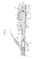
- - la figure 5 est une vue latérale du dispositif représenté à la figure 1 et comprend en plus certains éléments de l'appareil ;
- - la figure 6 est semblable à la figure 3, le disque étant cette fois un disque de grand diamètre ;
- - la figure 7 est semblable à la figure 4, le disque étant cette fois un disque de grand diamètre ;
- - les figures 8 et 9 sont des vues semblables aux figures 1 et 2 et représentent la seconde exécution ;
- - la figure 10 est une vue latérale partielle du dispositif selon la second exécution et comprend, comme à la figure 5, certains éléments de l'appareil ;
- - la figure 11 est une vue en perspective d'un élément de commande ;
- - la figure 12 est une vue de dessous d'un troisième mode de réalisation.
- - Figure 1 is a top view of a drawer according to the first embodiment, the assembly being in the output position (inoperative position);
- - Figure 2 is a bottom view of said drawer according to Figure 1;
- - Figure 3 is similar to Figure 2 after depositing a small diameter disc and activating the centering device;
- - Figure 4 is similar to Figure 3, the small diameter disc having been centered;
- - Figure 5 is a side view of the device shown in Figure 1 and further comprises certain elements of the apparatus;
- - Figure 6 is similar to Figure 3, the disc being this time a large diameter disc;
- - Figure 7 is similar to Figure 4, the disc being this time a large diameter disc;
- - Figures 8 and 9 are views similar to Figures 1 and 2 and show the second embodiment;
- - Figure 10 is a partial side view of the device according to the second embodiment and comprises, as in Figure 5, certain elements of the device;
- - Figure 11 is a perspective view of a control element;
- - Figure 12 is a bottom view of a third embodiment.
Comme représenté à la figure 1, le "tiroir" 1 est constitué d'un volume parallélépipèdique comportant d'une part une dépression circulaire 2 destinée à recevoir un disque 3 qui y est déposé par l'utilisateur et d'autre part, deux longerons 5, 5ʹ destinés à guider et à assurer, par rapport au châssis 100 de l'appareil, le mouvement de translation du tiroir 1 lors de son ouverture et de sa fermeture. La translation du tiroir est assurée par un moteur électrique réversible, non représenté, entraînant un engrenage 10 coopérant avec une crémaillère 12 solidaire de l'un des longerons 5 et donc du tiroir 1.As shown in Figure 1, the "drawer" 1 consists of a rectangular volume comprising on the one hand a
Au fond de la dépression circulaire 2 dimensionnée de telle sorte à recevoir et à centrer des disques 3 de grand diamètre (dans l'exemple présent diamètre de cinq pouces, soit environ 12,5 cms), sont pratiquées trois fentes 20, 21, 22 de formes appropriées et destinées chacune à permettre et éventuellement à guider le déplacement d'un axe ou téton 23, 24, 25. Ces axes ou tétons sont eux destinés à coopérer avec la périphérie des disques d'un diamètre inférieur à ceux pour lesquels la dépression 2 est conçue de façon à assurer le centrage par rapport à ladite dépression lors du mouvement de translation apportant le disque au-dessus de son plateau d'entraînement en vue de sa mise en position opérative.At the bottom of the
Comme représenté à la figure 2, ces trois tétons sont chacun montés à l'extrémité d'un support 27, 28, 29, ces trois supports voyant leurs mouvements coordonnés du fait de leur liaison à chacune de leur autre extrémité par un axe commun 30.As shown in FIG. 2, these three pins are each mounted at the end of a
Ainsi qu'il est représenté à cette même figure, le support 29 est un levier qui pivote autour d'un axe 31 monté au dos de la dépression circulaire 2 et y est maintenu par un anneau brisé.As shown in this same figure, the
Un ressort 32 dont les extrémités sont respectivement liées au boîtier du tiroir 1 et à l'extrémité du support 27 portant le téton 23, assure un retour élastique des trois supports dans la position représentée à la figure 2 dès qu'ils en sont écartés.A
A cette même extrémité du support 27 où sont respectivement fixé le téton 23 et attaché le ressort 32, il est prévu une patte 35 dont le niveau bas est inférieur à celui du tiroir 1 et qui est destinée à coopérer avec le profil 37 fixe, monté sur le châssis 100 de l'appareil de lecture (figures 4, 5 et 7).At this same end of the
Environ à mi-chemin entre le téton 23 et l'axe 30, le support 27 porte un axe 40 - voir figure 2 - destiné à coopérer avec une came 42 solidairement liée à une crémaillère 12 assurant la translation du tiroir 1 - voir figure 11.About halfway between the
La crémaillère 12 est reliée au longeron 5 du tiroir 1 par l'intermédiaire de tétons 60 et de fentes 61 au travers desquelles passent lesdits tétons (figures 5, 10 et 11) de façon à obtenir :
- un mouvement relatif de la crémaillère par rapport au tiroir,
- un mouvement solidaire de la crémaillère et du tiroir pour la translation de ce dernier.The
- a relative movement of the rack relative to the drawer,
- a movement integral with the rack and the drawer for the translation of the latter.
La commande permettant de solidariser, respectivement désolidariser le mouvement de la crémaillère 12 de celui du tiroir 1 s'effectue de la façon suivante :
- un ergot 87 porté par un levier 88 pivotant autour d'un axe 89 solidaire du tiroir 1 peut s'engager dans une entaille 91 prévue dans la crémaillère 12 et ce sous l'influence d'une patte élastique 94 prenant appui sur une butée 95 solidaire du longeron 5. Le dégagement de l'ergot 87 par rapport à l'entaille 91 est assurée par un tenon 96 porté par le levier 88 et coopérant avec une rampe 97 prévue dans une traverse 98 solidaire du châssis 100 de l'appareil.The command for securing, respectively disengaging, the movement of the
- A
Le mouvement de ces supports 27, 28, 29 pour assurer le centrage de disques d'un diamètre inférieur à celui des disques pour lesquels la dépression 2 est conçue, se fait de la manière suivante :
- le disque d'un diamètre de 8 cms environ est déposé au fond de la dépression 2 en n'importe quel endroit ;
- le moteur, non représenté, assurant la rotation de l'engrenage 10 est mis sous tension, soit automatiquement par détection de la présence du disque, soit manuellement par l'utilisateur (actionnement de la touche de chargement ou de lecture) et assure la translation de la crémaillère 12. Grâce à la liaison existant entre ladite crémaillère 12 et le tiroir 1, la crémaillère va dans un premier temps se déplacer sans entraîner le tiroir 1. Au cours de ce déplacement, la came 42 est translatée (figure 3) et l'axe 40 soumis par l'intermédiaire du support 27 à l'influence du ressort 32 s'appuie sur le profil 43 qui en se déplaçant permet un léger pivotement du support 27 et donc du téton 23 vers le centre de la dépression 2.The movement of these supports 27, 28, 29 to ensure the centering of discs with a diameter smaller than that of the discs for which the
- the disc with a diameter of approximately 8 cms is placed at the bottom of
- the motor, not shown, ensuring the rotation of the
Puisqu'un disque 3 de petit diamètre a été déposé dans ladite dépression 2 le pivotement du levier 27 n'est limité que par l'extrémité latérale de la fente 20 ce qui permet à l'axe 40 d'échapper à la came 42 (figure 3).Since a
Simultanément, la crémaillère 12 ayant achevé son mouvement relatif (l'ergot 87 étant dans l'entaille 91) par rapport au tiroir 1, ce dernier est alors solidairement translaté avec celle-ci et assure le transfert du disque vers sa position opérative.Simultaneously, the
Au cours de ce mouvement de translation, la patte 35 coopère avec le profil 37 monté sur le châssis de l'appareil de telle façon à être repoussée vers l'avant de l'appareil (flèche A - figure 3). De ce fait, le support 27 en ne pouvant plus suivre exactement le mouvement de translation du tiroir 1 va, grâce à la liaison assurée par l'axe 30, faire pivoter horlogiquement le support 29 autour de l'axe 31 et déplacer latéralement le support 28. Par là-même, les trois tétons 23, 24, 25 vont effectuer un déplacement coordonné vers le centre de la dépression 2 et donc assurer le centrage exact d'un disque de petit diamètre par rapport à la dépression 2 prévue pour assurer le centrage d'un disque de grand diamètre (12,5 cms) - figure 4.During this translational movement, the
Le profil 37 est dimensionné de telle sorte qu'à la fin de la translation du tiroir 1 et donc du mouvement de la mise en position opérative du disque 3 correctement centré, le support 27 puisse subir un léger mouvement de retour sous l'influence du ressort 32 de façon à légèrement dégager les trois tétons 23, 24, 25 de la périphérie du disque 3 pour en permettre la libre rotation en position opérative.The
Une autre possibilité est que le support 27 maintient à tout moment les trois tétons 23, 24, 25 dégagés c'est-à-dire à une certaine distance de la périphérie du disque 3 étant donné que le disque est finalement toujours correctement centré sur son moyen d'entraînement par la forme habituellement conique du moyen faisant partie du plateau d'entraînement 85.Another possibility is that the
Simultanément, les moyens ou supports assurant la descente, respectivement la montée du disque sur ou à partir du plateau d'entraînement sont actionnés. Dans le cas présent, ce mouvement vertical est assuré (figure 5) par la combinaision d'une plaquette 70 supportant le disque 3, soumise à l'influence d'un ressort 71 et pivotant autour d'un axe 72 et d'un bras 74 pivotant autour d'un axe 76 et soumis à l'influence d'un ressort 78.Simultaneously, the means or supports ensuring the descent, respectively the ascent of the disc on or from the drive plate are actuated. In the present case, this vertical movement is ensured (FIG. 5) by the combination of a
Le tiroir 1 comprend une rampe, non représentée, permettant le pivotement d'un bras 74 vers le bas et donc, par action de la butée 80 qu'il porte, la descente de la plaquette 70 en fin de course "avant" dudit tiroir, ce qui assure le positionnement du disque 3 sur ses moyens d'entraînement 85, la plaquette 70 étant alors suffisamment dégagée du disque pour en permettre la libre rotation.The
Lors de l'éjection d'un disque de petit diamètre, les étapes décrites ci-dessus se déroulement dans l'ordre inverse :
- le disque une fois ôté de son plateau d'entraînement est centré par la présence des trois tétons 23, 24, 25 - voir figure 4 ;
- le profil 37 et le ressort 32 permettent lors de la translation du chariot 1 le déplacement inverse des supports 27, 28, 29 et donc des tétons 23, 24, 25 qui retournent vers le bord de la dépression 2 - figure 3 ;
- en bout de translation (course arrière) du tiroir 1, la crémaillère effectue son mouvement relatif par rapport audit tiroir 1, la rampe 97 agissant sur le tenon 96 pour faire pivoter le levier 88 et donc dégager l'ergot 87 de l'entaille 91. La came 42, grâce à l'action de ses profils 44 puis 43, ramène l'axe 40 vers le bord extérieur du tiroir, et ce, à l'encontre du ressort 32 de façon à totalement écarter vers l'extérieur les trois tétons pour libérer la dépression 2 et permettre, après enlèvement du disque 3 de petit diamètre, le positionnement d'un disque 3 de grand diamètre (figures 1 et 2).When ejecting a small diameter disc, the steps described above take place in reverse order:
- the disc once removed from its drive plate is centered by the presence of the three
- The
- at the end of translation (back stroke) of the
Lorsqu'un disque 3 de grand diamètre, c'est-à-dire pour lequel est conçue la forme de la dépression, est positionné dans ladite dépression (figure 1) et que le moteur assurant l'entraînement de l'engrenage est mis sous tension afin d'amener ledit disque en position opérative, les supports effectuent le mouvement suivant:
- lors du déplacement relatif de la crémaillère 12 par rapport au tiroir 1, la came 42 est translatée, et comme précédemment l'axe 40, soumis à l'influence du ressort, suit le profil 43 de ladite came. Cependant, le diamètre du disque 3, très légèrement inférieur à celui de la dépression 2, ne permet qu'un faible déplacement (figure 6) vers le centre de la dépression 2 du téton 23 et donc de l'axe 40. Celui-ci, ne pouvant parcourir le profil 44, tombe ensuite (voir figure 7) dans la fourche assurée par le profil 45 qui alors ramène le téton 23 dans sa position initiale en l'écartant de la périphérie du disque 3 afin d'en permettre la libre rotation en position opérative ;
- simultanément, la crémaillère 12 ayant achevé son mouvement relatif par rapport au tiroir 1, ce dernier est alors solidairement translaté avec celle-ci et assure le transfert du disque vers sa position opérative (figure 7).When a
- During the relative movement of the
- Simultaneously, the
La fourche 45 en maintenant l'axe 40 dans la position représentée à la figure 7, empêche le profil 37 de coopérer avec la platte 35 et de ce fait les supports 27, 28, 29 et donc les tétons 23, 24, 25 ne subissent aucun déplacement et la libre rotation du disque est assurée.The
La descente du disque sur ses moyens d'entraînement est assurée de la même façon que pour le cas d'un disque de plus faible diamètre.The lowering of the disc on its drive means is ensured in the same way as for the case of a disc of smaller diameter.
A l'éjection d'un disque 3 de grand diamètre, les mouvements décrits ci-dessus se font dans le sens inverse et pour les mêmes raisons qu'exposées précédemment, l'axe 40 suit le profil 45 puis le profil 43 et ainsi assure le retour des trois tétons 23, 24, 25 en position extrême de sortie (figures 1 et 2), le dispositif étant prêt, après que le disque 3 ait été retiré, à recevoir et centrer un disque de n'importe quel diamètre.When a
Comme mentionné dans l'introduction, cette exécution assure avantageusement la combinaison du dispositif décrit ci-dessus avec le système de chargement objet du brevet no 905.639 de la demanderesse auquel on se référera avantageusement pour toute explication relative à son fonctionnement.As mentioned in the introduction, this embodiment advantageously provides a combination of the device described above with the patent subject loading system No. 905 639 of the Applicant to which one will advantageously refer to any explanation as to its operation.
Tous les éléments décrits dans le premier mode d'exécution se retrouvent avec les mêmes références dans ce second mode, moyennant les additions suivantes (voir figures 8 à 10) :
- le fond de la dépression 2 est en partie constitué d'un support 120 pivotant autour d'un axe 122 et possédant latéralement un axe 124 destiné à coopérer avec le profil 127 d'une came 126 solidaire de la crémaillère 12 - voir figure 10.All the elements described in the first embodiment are found with the same references in this second mode, with the following additions (see FIGS. 8 to 10):
- The bottom of the
Lors du mouvement relatif de la crémaillère 12 par rapport au tiroir 1, le profil 127 agit sur l'axe 124 pour assurer le pivotement vers la bas ou vers le haut, et ce, selon le sens de translation de la crémaillère 12, du support 120 assurant ainsi le relèvement ou l'abaissement angulaire du disque 3 comme prévu dans le brevet belge no 905.639 de la demanderesse.During the relative movement of the
Dans les exécutions précédentes, la crémaillère et le tiroir sont liés par des moyens leur permettant un mouvement relatif initial pendant lequel a lieu la détection du diamètre du disque. Le tiroir n'est entraîné en mouvement qu'après cette phase.In the previous embodiments, the rack and the drawer are linked by means allowing them an initial relative movement during which the diameter of the disc is detected. The drawer is not driven in motion until after this phase.
Selon l'exécution représentée à la figure 12, la crémaillère 200 entraînant le tiroir 1 est ici solidaire dudit tiroir et par conséquent la rotation de l'engrenage 204 assure aussitôt les déplacements du tiroir.According to the embodiment shown in Figure 12, the
Sur cette figure, à l'exception d'un guide 206, les pièces du châssis situées sous le tiroir n'ont pas été représentées dans un but de simplification.In this figure, with the exception of a
Comme précédemment, le tiroir 1 comprend trois supports 27, 28 et 29 ayant chacun à l'une de leurs extrémités un téton 23, 24 et 25, coopérant avec la périphérie du disque placé par l'utilisateur.As before, the
L'un de ces supports, en l'occurrence le 27, sert également à détecter le diamètre du disque à l'aide d'une prolongation 211 supportant un axe 212 coopérant avec le guide fixe 206. Ce même support 27 est soumis à l'action de moyens élastiques 32 ancrés au tiroir 1.One of these supports, in this
Le guide 206 a deux canaux 216, 218 destinés à guider l'axe 212 ainsi qu'une butée 220.The
Après positionnement d'un disque par l'utilisateur, le tiroir est translaté vers l'intérieur de l'appareil, soit automatiquement soit en réponse à une commande de l'utilisateur, à l'aide d'un moteur (non représenté) entraînant l'engrenage 204. Lorsque l'axe 212 suit le guide 206, les moyens élastiques 32 tendent à faire pivoter le support 27 horlogiquement et dans le cas où le disque est de petit diamètre, ce pivotement sera tel que l'axe 212 va parcourir le canal 218 pour venir contre la butée 220.After positioning of a disc by the user, the drawer is translated towards the interior of the device, either automatically or in response to a command from the user, using a motor (not shown) driving the
La poursuite du mouvement de translation du tiroir commandera alors le déplacement coordonné des trois supports 27, 28 et 29 et donc des trois tétons 23, 24 et 25 assurant le centrage du disque comme décrit précédemment.Continuation of the translational movement of the drawer will then command the coordinated movement of the three
Si maintenant le disque positionné par l'utilisateur est de grand diamètre, le téton 23 en venant contre la périphérie de ce disque n'effectue qu'un très léger pivotement et par conséquent l'axe 212 suivra le canal 216, qui de par son dimensionnement ramène le support 27 en position inopérative et donc le téton 23 à l'écart de la périphérie du disque pour en permettre la libre rotation.If now the disc positioned by the user is of large diameter, the
Bien que les différentes exécutions soient décrites pour des disques de deux diamètres différents, on comprend aisément qu'elles peuvent s'appliquer à des disques de diamètres intermédiaires, par exemples quatre pouces, sans pour autant sortir du cadre de l'invention.Although the different embodiments are described for discs of two different diameters, it is easily understood that they can be applied to discs of intermediate diameters, for example four inches, without departing from the scope of the invention.
En effet, si un tel disque était positionné dans la dépression 2 et le mouvement de chargement entamé, le téton 23 pourrait pivoter mais d'un angle moindre que s'il s'agissait d'un disque de plus petit diamètre.Indeed, if such a disc was positioned in the
Par conséquent, en modifiant les formes de la fente 20 pour tenir compte d'un plus faible pivotement du téton 23, des profils 43, 44 et 45 et de la came 42 et en rajoutant soit un profil fixe 37, soit un canal 218 de longueur appropriée ; le dispositif peut également centrer un disque d'un diamètre intermédiaire.Consequently, by modifying the shapes of the
Claims (16)
Applications Claiming Priority (2)
| Application Number | Priority Date | Filing Date | Title |
|---|---|---|---|
| BE8700386 | 1987-04-13 | ||
| BE8700386A BE1000472A4 (en) | 1987-04-13 | 1987-04-13 | LOADING DEVICE AUTOMATIC DISC OF DIFFERENT DIAMETERS ON ROTARY TRAY RUNS-Hard. |
Publications (3)
| Publication Number | Publication Date |
|---|---|
| EP0286770A2 true EP0286770A2 (en) | 1988-10-19 |
| EP0286770A3 EP0286770A3 (en) | 1989-01-11 |
| EP0286770B1 EP0286770B1 (en) | 1991-11-21 |
Family
ID=3882609
Family Applications (1)
| Application Number | Title | Priority Date | Filing Date |
|---|---|---|---|
| EP87870172A Expired - Lifetime EP0286770B1 (en) | 1987-04-13 | 1987-12-09 | Device for automatically centering discs with different diameters on the loading means of a disc player |
Country Status (6)
| Country | Link |
|---|---|
| US (1) | US4839880A (en) |
| EP (1) | EP0286770B1 (en) |
| JP (1) | JPH07118139B2 (en) |
| KR (1) | KR880013134A (en) |
| BE (1) | BE1000472A4 (en) |
| DE (1) | DE3774699D1 (en) |
Cited By (5)
| Publication number | Priority date | Publication date | Assignee | Title |
|---|---|---|---|---|
| EP0265410A2 (en) * | 1986-10-22 | 1988-04-27 | Staar Societe Anonyme | Apparatus for loading and unloading record disc player |
| EP0331663A2 (en) * | 1988-03-02 | 1989-09-06 | Staar Societe Anonyme | Automatic disc centering mechanism |
| EP0434136A1 (en) * | 1989-12-20 | 1991-06-26 | Koninklijke Philips Electronics N.V. | Disc-record player and centring device for use in the player |
| EP0653751A2 (en) * | 1993-11-12 | 1995-05-17 | Nakamichi Corporation | Device for driving trays in disk players |
| EP0685842A3 (en) * | 1994-06-01 | 1996-12-04 | Aiwa Co | Auto disc changer. |
Families Citing this family (15)
| Publication number | Priority date | Publication date | Assignee | Title |
|---|---|---|---|---|
| JPH067491Y2 (en) * | 1988-05-16 | 1994-02-23 | 武美 小岩 | Rotating disk mounting mechanism |
| BE1002664A3 (en) * | 1988-11-17 | 1991-04-30 | Staar Sa | LOADING, EJECTING AND CENTERING DEVICE FOR DISCS OF DIFFERENT DIAMETERS. |
| DE3843991A1 (en) * | 1988-12-27 | 1990-07-05 | Thomson Brandt Gmbh | RECORDING DEVICE FOR A RECORDING AND / OR PLAYBACK DEVICE |
| JPH02183458A (en) * | 1989-01-09 | 1990-07-18 | Clarion Co Ltd | Disk loading mechanism |
| DE4004562B4 (en) * | 1989-02-16 | 2008-05-08 | Pioneer Electronic Corp. | In-vehicle turntable |
| US5226028A (en) * | 1989-02-16 | 1993-07-06 | Pioneer Electronic Corporation | Centering mechanism for automotive disk player |
| US4933927A (en) * | 1989-02-24 | 1990-06-12 | Conner Peripherals, Inc. | Disk centering method and apparatus for centering disks for disk drives |
| JPH0697532B2 (en) * | 1989-03-03 | 1994-11-30 | パイオニア株式会社 | Disc player |
| JPH0679405B2 (en) * | 1989-08-11 | 1994-10-05 | パイオニア株式会社 | Disc player |
| US5043973A (en) * | 1990-07-30 | 1991-08-27 | Conner Peripherals, Inc. | Disk centering method and apparatus for centering disks for disk drives |
| KR970006819B1 (en) * | 1992-11-30 | 1997-04-30 | 대우전자 주식회사 | Loading apparatus of a multi-disk player |
| JP3404925B2 (en) * | 1994-10-24 | 2003-05-12 | ミツミ電機株式会社 | Disk unit |
| JP3410997B2 (en) * | 1999-10-06 | 2003-05-26 | 株式会社ソニー・コンピュータエンタテインメント | Disk unit and disk tray |
| JP4271192B2 (en) * | 2005-01-24 | 2009-06-03 | 富士通テン株式会社 | Disc changer |
| CN111375710B (en) * | 2020-03-29 | 2021-08-27 | 贺平 | Steel reinforcement cage mold processing |
Citations (9)
| Publication number | Priority date | Publication date | Assignee | Title |
|---|---|---|---|---|
| US2508715A (en) * | 1945-04-18 | 1950-05-23 | Philco Corp | Phonograph apparatus |
| FR2343307A1 (en) * | 1976-03-02 | 1977-09-30 | Sony Corp | DISC READING EQUIPMENT IN PARTICULAR ELECTROPHONE |
| JPS5365704A (en) * | 1976-11-24 | 1978-06-12 | Sony Corp | Concentrator of recording disc in auto-player |
| GB2139800A (en) * | 1983-03-11 | 1984-11-14 | Pioneer Electronic Corp | Automatic loading disc player |
| US4497051A (en) * | 1981-02-05 | 1985-01-29 | Pioneer Electronic Corporation | Automatic record loading player |
| US4498162A (en) * | 1982-04-23 | 1985-02-05 | Staar S. A. | Automatic disc loading apparatus |
| US4523306A (en) * | 1983-01-28 | 1985-06-11 | Staar S. A. | Record loading apparatus for a slot type record player |
| EP0185140A2 (en) * | 1984-12-19 | 1986-06-25 | Kabushiki Kaisha Toshiba | Disk playback apparatus |
| EP0200705A2 (en) * | 1985-04-23 | 1986-11-05 | Staar Societe Anonyme | Automatic disc loading and unloading mechanism for record player apparatus |
Family Cites Families (2)
| Publication number | Priority date | Publication date | Assignee | Title |
|---|---|---|---|---|
| US3305239A (en) * | 1964-10-19 | 1967-02-21 | Zenith Radio Corp | Position trip |
| US3345775A (en) * | 1965-08-25 | 1967-10-10 | Diebold Inc | Fire door |
-
1987
- 1987-04-13 BE BE8700386A patent/BE1000472A4/en not_active IP Right Cessation
- 1987-09-24 US US07/100,631 patent/US4839880A/en not_active Expired - Lifetime
- 1987-12-09 DE DE8787870172T patent/DE3774699D1/en not_active Expired - Fee Related
- 1987-12-09 EP EP87870172A patent/EP0286770B1/en not_active Expired - Lifetime
- 1987-12-25 JP JP62327543A patent/JPH07118139B2/en not_active Expired - Fee Related
- 1987-12-28 KR KR1019870015053A patent/KR880013134A/en not_active Application Discontinuation
Patent Citations (9)
| Publication number | Priority date | Publication date | Assignee | Title |
|---|---|---|---|---|
| US2508715A (en) * | 1945-04-18 | 1950-05-23 | Philco Corp | Phonograph apparatus |
| FR2343307A1 (en) * | 1976-03-02 | 1977-09-30 | Sony Corp | DISC READING EQUIPMENT IN PARTICULAR ELECTROPHONE |
| JPS5365704A (en) * | 1976-11-24 | 1978-06-12 | Sony Corp | Concentrator of recording disc in auto-player |
| US4497051A (en) * | 1981-02-05 | 1985-01-29 | Pioneer Electronic Corporation | Automatic record loading player |
| US4498162A (en) * | 1982-04-23 | 1985-02-05 | Staar S. A. | Automatic disc loading apparatus |
| US4523306A (en) * | 1983-01-28 | 1985-06-11 | Staar S. A. | Record loading apparatus for a slot type record player |
| GB2139800A (en) * | 1983-03-11 | 1984-11-14 | Pioneer Electronic Corp | Automatic loading disc player |
| EP0185140A2 (en) * | 1984-12-19 | 1986-06-25 | Kabushiki Kaisha Toshiba | Disk playback apparatus |
| EP0200705A2 (en) * | 1985-04-23 | 1986-11-05 | Staar Societe Anonyme | Automatic disc loading and unloading mechanism for record player apparatus |
Non-Patent Citations (1)
| Title |
|---|
| PATENT ABSTRACTS OF JAPAN, vol. 2, no. 99, 17 août 1978, page 5032 E 78; & JP-A-53 065 704 (SONY) 12-06-1978 * |
Cited By (9)
| Publication number | Priority date | Publication date | Assignee | Title |
|---|---|---|---|---|
| EP0265410A2 (en) * | 1986-10-22 | 1988-04-27 | Staar Societe Anonyme | Apparatus for loading and unloading record disc player |
| EP0265410A3 (en) * | 1986-10-22 | 1989-07-19 | Staar Sa | Apparatus for loading and unloading record disc player. |
| EP0331663A2 (en) * | 1988-03-02 | 1989-09-06 | Staar Societe Anonyme | Automatic disc centering mechanism |
| EP0331663A3 (en) * | 1988-03-02 | 1990-09-26 | Staar Societe Anonyme | Automatic disc centering mechanism |
| EP0434136A1 (en) * | 1989-12-20 | 1991-06-26 | Koninklijke Philips Electronics N.V. | Disc-record player and centring device for use in the player |
| EP0653751A2 (en) * | 1993-11-12 | 1995-05-17 | Nakamichi Corporation | Device for driving trays in disk players |
| EP0653751A3 (en) * | 1993-11-12 | 1995-07-19 | Nakamichi Corp | Device for driving trays in disk players. |
| US5574711A (en) * | 1993-11-12 | 1996-11-12 | Nakamichi Corporation | Device for driving trays in disk players |
| EP0685842A3 (en) * | 1994-06-01 | 1996-12-04 | Aiwa Co | Auto disc changer. |
Also Published As
| Publication number | Publication date |
|---|---|
| JPH07118139B2 (en) | 1995-12-18 |
| US4839880A (en) | 1989-06-13 |
| JPS63257952A (en) | 1988-10-25 |
| BE1000472A4 (en) | 1988-12-20 |
| EP0286770B1 (en) | 1991-11-21 |
| EP0286770A3 (en) | 1989-01-11 |
| KR880013134A (en) | 1988-11-30 |
| DE3774699D1 (en) | 1992-01-02 |
Similar Documents
| Publication | Publication Date | Title |
|---|---|---|
| EP0286770B1 (en) | Device for automatically centering discs with different diameters on the loading means of a disc player | |
| FR2538597A1 (en) | DISC LOADING DEVICE | |
| FR2488714A1 (en) | FLEXIBLE MAGNETIC DISK CASSETTE | |
| FR2563650A1 (en) | LOADING APPARATUS FOR A DISK DRIVE | |
| FR2565392A1 (en) | AUTOMATIC DISK CHANGE DISK DRIVE COMPRISING A LATCHING ELEMENT FOR LOCKING THE DISK CHARGER TO THE MECHANISM, DISK CHARGER, AND READING INFORMATION SIGNALS | |
| FR2488715A1 (en) | FLEXIBLE MAGNETIC DISC CASSETTE AND RECORDING AND / OR REPRODUCING APPARATUS USING SUCH A DISK | |
| FR2565391A1 (en) | APPARATUS FOR RECORDING AND / OR REPRODUCING SELECTIVE AND / OR SUCCESSIVE DISCS OR CASSETTES OF THE CHANGER TYPE | |
| FR2702078A1 (en) | Assembly for electrophone with a movable plate. | |
| EP0541503A1 (en) | Transfer device for an information carrier | |
| EP0718837B1 (en) | Turning table with disc clamping means | |
| FR2653259A1 (en) | DISC LOADING DEVICE FOR DISC PLAYER. | |
| FR2539543A1 (en) | LOCKING DEVICE FOR TURNKEY APPARATUS | |
| FR2551578A1 (en) | APPARATUS FOR RECORDING AND / OR READING A SOFT DISK | |
| EP0183672A2 (en) | Recording and reproducing apparatus with frontal insertion | |
| FR2692071A1 (en) | Turntable. | |
| FR2504304A1 (en) | AUTOMATIC DEVICE FOR TURNING THE DISC IN A RECORDING APPARATUS | |
| EP0369978A2 (en) | Loading, unloading and centering device for discs with different diameters | |
| FR2539547A1 (en) | REPRODUCING APPARATUS FOR ROTATING RECORDING MEDIA | |
| EP0415805B1 (en) | Consignment deposit for rigid fixing type of trolleys and trolleys provided with such a device | |
| FR2693022A1 (en) | Turntable. | |
| EP0369859B1 (en) | Device for the backlash-free driving of a magnetic-tape cassette reel | |
| FR2479527A1 (en) | AUTOMATIC CASSETTES TURNING DEVICE | |
| EP0461968B1 (en) | Recording-reproducing apparatus for discs | |
| BE882542A (en) | AUTOMATIC CASSETTE TURNING APPARATUS | |
| EP0783166B1 (en) | Checking and centering device for cassette loading |
Legal Events
| Date | Code | Title | Description |
|---|---|---|---|
| PUAI | Public reference made under article 153(3) epc to a published international application that has entered the european phase |
Free format text: ORIGINAL CODE: 0009012 |
|
| AK | Designated contracting states |
Kind code of ref document: A2 Designated state(s): BE CH DE FR GB IT LI NL SE |
|
| PUAL | Search report despatched |
Free format text: ORIGINAL CODE: 0009013 |
|
| AK | Designated contracting states |
Kind code of ref document: A3 Designated state(s): BE CH DE FR GB IT LI NL SE |
|
| 17P | Request for examination filed |
Effective date: 19890124 |
|
| 17Q | First examination report despatched |
Effective date: 19900927 |
|
| GRAA | (expected) grant |
Free format text: ORIGINAL CODE: 0009210 |
|
| AK | Designated contracting states |
Kind code of ref document: B1 Designated state(s): BE CH DE FR GB IT LI NL SE |
|
| ITF | It: translation for a ep patent filed |
Owner name: BARZANO' E ZANARDO MILANO S.P.A. |
|
| PG25 | Lapsed in a contracting state [announced via postgrant information from national office to epo] |
Ref country code: SE Effective date: 19911121 Ref country code: NL Effective date: 19911121 |
|
| GBT | Gb: translation of ep patent filed (gb section 77(6)(a)/1977) | ||
| PG25 | Lapsed in a contracting state [announced via postgrant information from national office to epo] |
Ref country code: LI Effective date: 19911231 Ref country code: CH Effective date: 19911231 Ref country code: BE Effective date: 19911231 |
|
| REF | Corresponds to: |
Ref document number: 3774699 Country of ref document: DE Date of ref document: 19920102 |
|
| NLV1 | Nl: lapsed or annulled due to failure to fulfill the requirements of art. 29p and 29m of the patents act | ||
| BERE | Be: lapsed |
Owner name: S.A. STAAR Effective date: 19911231 |
|
| REG | Reference to a national code |
Ref country code: CH Ref legal event code: PL |
|
| PLBE | No opposition filed within time limit |
Free format text: ORIGINAL CODE: 0009261 |
|
| STAA | Information on the status of an ep patent application or granted ep patent |
Free format text: STATUS: NO OPPOSITION FILED WITHIN TIME LIMIT |
|
| 26N | No opposition filed | ||
| REG | Reference to a national code |
Ref country code: GB Ref legal event code: 746 Effective date: 19991116 |
|
| REG | Reference to a national code |
Ref country code: GB Ref legal event code: IF02 |
|
| PGFP | Annual fee paid to national office [announced via postgrant information from national office to epo] |
Ref country code: DE Payment date: 20031218 Year of fee payment: 17 |
|
| PGFP | Annual fee paid to national office [announced via postgrant information from national office to epo] |
Ref country code: GB Payment date: 20041215 Year of fee payment: 18 |
|
| PGFP | Annual fee paid to national office [announced via postgrant information from national office to epo] |
Ref country code: FR Payment date: 20041216 Year of fee payment: 18 |
|
| PG25 | Lapsed in a contracting state [announced via postgrant information from national office to epo] |
Ref country code: DE Free format text: LAPSE BECAUSE OF NON-PAYMENT OF DUE FEES Effective date: 20050701 |
|
| PG25 | Lapsed in a contracting state [announced via postgrant information from national office to epo] |
Ref country code: IT Free format text: LAPSE BECAUSE OF NON-PAYMENT OF DUE FEES;WARNING: LAPSES OF ITALIAN PATENTS WITH EFFECTIVE DATE BEFORE 2007 MAY HAVE OCCURRED AT ANY TIME BEFORE 2007. THE CORRECT EFFECTIVE DATE MAY BE DIFFERENT FROM THE ONE RECORDED. Effective date: 20051209 Ref country code: GB Free format text: LAPSE BECAUSE OF NON-PAYMENT OF DUE FEES Effective date: 20051209 |
|
| GBPC | Gb: european patent ceased through non-payment of renewal fee |
Effective date: 20051209 |
|
| PG25 | Lapsed in a contracting state [announced via postgrant information from national office to epo] |
Ref country code: FR Free format text: LAPSE BECAUSE OF NON-PAYMENT OF DUE FEES Effective date: 20060831 |
|
| REG | Reference to a national code |
Ref country code: FR Ref legal event code: ST Effective date: 20060831 |