EP0286571B1 - Improved sound absorption in foam core panels and their method of manufacture - Google Patents
Improved sound absorption in foam core panels and their method of manufacture Download PDFInfo
- Publication number
- EP0286571B1 EP0286571B1 EP88630060A EP88630060A EP0286571B1 EP 0286571 B1 EP0286571 B1 EP 0286571B1 EP 88630060 A EP88630060 A EP 88630060A EP 88630060 A EP88630060 A EP 88630060A EP 0286571 B1 EP0286571 B1 EP 0286571B1
- Authority
- EP
- European Patent Office
- Prior art keywords
- panel
- foam
- cell structure
- facing material
- foam core
- Prior art date
- Legal status (The legal status is an assumption and is not a legal conclusion. Google has not performed a legal analysis and makes no representation as to the accuracy of the status listed.)
- Expired - Lifetime
Links
Images

Classifications
-
- B—PERFORMING OPERATIONS; TRANSPORTING
- B29—WORKING OF PLASTICS; WORKING OF SUBSTANCES IN A PLASTIC STATE IN GENERAL
- B29C—SHAPING OR JOINING OF PLASTICS; SHAPING OF MATERIAL IN A PLASTIC STATE, NOT OTHERWISE PROVIDED FOR; AFTER-TREATMENT OF THE SHAPED PRODUCTS, e.g. REPAIRING
- B29C51/00—Shaping by thermoforming, i.e. shaping sheets or sheet like preforms after heating, e.g. shaping sheets in matched moulds or by deep-drawing; Apparatus therefor
- B29C51/14—Shaping by thermoforming, i.e. shaping sheets or sheet like preforms after heating, e.g. shaping sheets in matched moulds or by deep-drawing; Apparatus therefor using multilayered preforms or sheets
- B29C51/145—Shaping by thermoforming, i.e. shaping sheets or sheet like preforms after heating, e.g. shaping sheets in matched moulds or by deep-drawing; Apparatus therefor using multilayered preforms or sheets having at least one layer of textile or fibrous material combined with at least one plastics layer
-
- B—PERFORMING OPERATIONS; TRANSPORTING
- B29—WORKING OF PLASTICS; WORKING OF SUBSTANCES IN A PLASTIC STATE IN GENERAL
- B29C—SHAPING OR JOINING OF PLASTICS; SHAPING OF MATERIAL IN A PLASTIC STATE, NOT OTHERWISE PROVIDED FOR; AFTER-TREATMENT OF THE SHAPED PRODUCTS, e.g. REPAIRING
- B29C44/00—Shaping by internal pressure generated in the material, e.g. swelling or foaming ; Producing porous or cellular expanded plastics articles
- B29C44/20—Shaping by internal pressure generated in the material, e.g. swelling or foaming ; Producing porous or cellular expanded plastics articles for articles of indefinite length
- B29C44/22—Shaping by internal pressure generated in the material, e.g. swelling or foaming ; Producing porous or cellular expanded plastics articles for articles of indefinite length consisting of at least two parts of chemically or physically different materials, e.g. having different densities
-
- B—PERFORMING OPERATIONS; TRANSPORTING
- B29—WORKING OF PLASTICS; WORKING OF SUBSTANCES IN A PLASTIC STATE IN GENERAL
- B29C—SHAPING OR JOINING OF PLASTICS; SHAPING OF MATERIAL IN A PLASTIC STATE, NOT OTHERWISE PROVIDED FOR; AFTER-TREATMENT OF THE SHAPED PRODUCTS, e.g. REPAIRING
- B29C44/00—Shaping by internal pressure generated in the material, e.g. swelling or foaming ; Producing porous or cellular expanded plastics articles
- B29C44/20—Shaping by internal pressure generated in the material, e.g. swelling or foaming ; Producing porous or cellular expanded plastics articles for articles of indefinite length
- B29C44/32—Incorporating or moulding on preformed parts, e.g. linings, inserts or reinforcements
- B29C44/321—Incorporating or moulding on preformed parts, e.g. linings, inserts or reinforcements the preformed part being a lining, e.g. a film or a support lining
-
- B—PERFORMING OPERATIONS; TRANSPORTING
- B29—WORKING OF PLASTICS; WORKING OF SUBSTANCES IN A PLASTIC STATE IN GENERAL
- B29C—SHAPING OR JOINING OF PLASTICS; SHAPING OF MATERIAL IN A PLASTIC STATE, NOT OTHERWISE PROVIDED FOR; AFTER-TREATMENT OF THE SHAPED PRODUCTS, e.g. REPAIRING
- B29C44/00—Shaping by internal pressure generated in the material, e.g. swelling or foaming ; Producing porous or cellular expanded plastics articles
- B29C44/34—Auxiliary operations
- B29C44/56—After-treatment of articles, e.g. for altering the shape
- B29C44/5627—After-treatment of articles, e.g. for altering the shape by mechanical deformation, e.g. crushing, embossing, stretching
- B29C44/5654—Subdividing foamed articles to obtain particular surface properties, e.g. on multiple modules
-
- B—PERFORMING OPERATIONS; TRANSPORTING
- B29—WORKING OF PLASTICS; WORKING OF SUBSTANCES IN A PLASTIC STATE IN GENERAL
- B29C—SHAPING OR JOINING OF PLASTICS; SHAPING OF MATERIAL IN A PLASTIC STATE, NOT OTHERWISE PROVIDED FOR; AFTER-TREATMENT OF THE SHAPED PRODUCTS, e.g. REPAIRING
- B29C48/00—Extrusion moulding, i.e. expressing the moulding material through a die or nozzle which imparts the desired form; Apparatus therefor
- B29C48/03—Extrusion moulding, i.e. expressing the moulding material through a die or nozzle which imparts the desired form; Apparatus therefor characterised by the shape of the extruded material at extrusion
- B29C48/07—Flat, e.g. panels
-
- B—PERFORMING OPERATIONS; TRANSPORTING
- B29—WORKING OF PLASTICS; WORKING OF SUBSTANCES IN A PLASTIC STATE IN GENERAL
- B29C—SHAPING OR JOINING OF PLASTICS; SHAPING OF MATERIAL IN A PLASTIC STATE, NOT OTHERWISE PROVIDED FOR; AFTER-TREATMENT OF THE SHAPED PRODUCTS, e.g. REPAIRING
- B29C69/00—Combinations of shaping techniques not provided for in a single one of main groups B29C39/00 - B29C67/00, e.g. associations of moulding and joining techniques; Apparatus therefore
- B29C69/001—Combinations of shaping techniques not provided for in a single one of main groups B29C39/00 - B29C67/00, e.g. associations of moulding and joining techniques; Apparatus therefore a shaping technique combined with cutting, e.g. in parts or slices combined with rearranging and joining the cut parts
-
- B—PERFORMING OPERATIONS; TRANSPORTING
- B29—WORKING OF PLASTICS; WORKING OF SUBSTANCES IN A PLASTIC STATE IN GENERAL
- B29C—SHAPING OR JOINING OF PLASTICS; SHAPING OF MATERIAL IN A PLASTIC STATE, NOT OTHERWISE PROVIDED FOR; AFTER-TREATMENT OF THE SHAPED PRODUCTS, e.g. REPAIRING
- B29C48/00—Extrusion moulding, i.e. expressing the moulding material through a die or nozzle which imparts the desired form; Apparatus therefor
- B29C48/001—Combinations of extrusion moulding with other shaping operations
- B29C48/0011—Combinations of extrusion moulding with other shaping operations combined with compression moulding
-
- B—PERFORMING OPERATIONS; TRANSPORTING
- B29—WORKING OF PLASTICS; WORKING OF SUBSTANCES IN A PLASTIC STATE IN GENERAL
- B29C—SHAPING OR JOINING OF PLASTICS; SHAPING OF MATERIAL IN A PLASTIC STATE, NOT OTHERWISE PROVIDED FOR; AFTER-TREATMENT OF THE SHAPED PRODUCTS, e.g. REPAIRING
- B29C48/00—Extrusion moulding, i.e. expressing the moulding material through a die or nozzle which imparts the desired form; Apparatus therefor
- B29C48/001—Combinations of extrusion moulding with other shaping operations
- B29C48/0012—Combinations of extrusion moulding with other shaping operations combined with shaping by internal pressure generated in the material, e.g. foaming
-
- B—PERFORMING OPERATIONS; TRANSPORTING
- B29—WORKING OF PLASTICS; WORKING OF SUBSTANCES IN A PLASTIC STATE IN GENERAL
- B29C—SHAPING OR JOINING OF PLASTICS; SHAPING OF MATERIAL IN A PLASTIC STATE, NOT OTHERWISE PROVIDED FOR; AFTER-TREATMENT OF THE SHAPED PRODUCTS, e.g. REPAIRING
- B29C48/00—Extrusion moulding, i.e. expressing the moulding material through a die or nozzle which imparts the desired form; Apparatus therefor
- B29C48/001—Combinations of extrusion moulding with other shaping operations
- B29C48/0017—Combinations of extrusion moulding with other shaping operations combined with blow-moulding or thermoforming
-
- B—PERFORMING OPERATIONS; TRANSPORTING
- B29—WORKING OF PLASTICS; WORKING OF SUBSTANCES IN A PLASTIC STATE IN GENERAL
- B29C—SHAPING OR JOINING OF PLASTICS; SHAPING OF MATERIAL IN A PLASTIC STATE, NOT OTHERWISE PROVIDED FOR; AFTER-TREATMENT OF THE SHAPED PRODUCTS, e.g. REPAIRING
- B29C51/00—Shaping by thermoforming, i.e. shaping sheets or sheet like preforms after heating, e.g. shaping sheets in matched moulds or by deep-drawing; Apparatus therefor
- B29C51/08—Deep drawing or matched-mould forming, i.e. using mechanical means only
- B29C51/082—Deep drawing or matched-mould forming, i.e. using mechanical means only by shaping between complementary mould parts
-
- B—PERFORMING OPERATIONS; TRANSPORTING
- B29—WORKING OF PLASTICS; WORKING OF SUBSTANCES IN A PLASTIC STATE IN GENERAL
- B29K—INDEXING SCHEME ASSOCIATED WITH SUBCLASSES B29B, B29C OR B29D, RELATING TO MOULDING MATERIALS OR TO MATERIALS FOR MOULDS, REINFORCEMENTS, FILLERS OR PREFORMED PARTS, e.g. INSERTS
- B29K2105/00—Condition, form or state of moulded material or of the material to be shaped
- B29K2105/04—Condition, form or state of moulded material or of the material to be shaped cellular or porous
- B29K2105/045—Condition, form or state of moulded material or of the material to be shaped cellular or porous with open cells
-
- B—PERFORMING OPERATIONS; TRANSPORTING
- B29—WORKING OF PLASTICS; WORKING OF SUBSTANCES IN A PLASTIC STATE IN GENERAL
- B29L—INDEXING SCHEME ASSOCIATED WITH SUBCLASS B29C, RELATING TO PARTICULAR ARTICLES
- B29L2031/00—Other particular articles
- B29L2031/30—Vehicles, e.g. ships or aircraft, or body parts thereof
- B29L2031/3005—Body finishings
-
- Y—GENERAL TAGGING OF NEW TECHNOLOGICAL DEVELOPMENTS; GENERAL TAGGING OF CROSS-SECTIONAL TECHNOLOGIES SPANNING OVER SEVERAL SECTIONS OF THE IPC; TECHNICAL SUBJECTS COVERED BY FORMER USPC CROSS-REFERENCE ART COLLECTIONS [XRACs] AND DIGESTS
- Y10—TECHNICAL SUBJECTS COVERED BY FORMER USPC
- Y10T—TECHNICAL SUBJECTS COVERED BY FORMER US CLASSIFICATION
- Y10T156/00—Adhesive bonding and miscellaneous chemical manufacture
- Y10T156/10—Methods of surface bonding and/or assembly therefor
- Y10T156/1002—Methods of surface bonding and/or assembly therefor with permanent bending or reshaping or surface deformation of self sustaining lamina
- Y10T156/1043—Subsequent to assembly
-
- Y—GENERAL TAGGING OF NEW TECHNOLOGICAL DEVELOPMENTS; GENERAL TAGGING OF CROSS-SECTIONAL TECHNOLOGIES SPANNING OVER SEVERAL SECTIONS OF THE IPC; TECHNICAL SUBJECTS COVERED BY FORMER USPC CROSS-REFERENCE ART COLLECTIONS [XRACs] AND DIGESTS
- Y10—TECHNICAL SUBJECTS COVERED BY FORMER USPC
- Y10T—TECHNICAL SUBJECTS COVERED BY FORMER US CLASSIFICATION
- Y10T156/00—Adhesive bonding and miscellaneous chemical manufacture
- Y10T156/10—Methods of surface bonding and/or assembly therefor
- Y10T156/1052—Methods of surface bonding and/or assembly therefor with cutting, punching, tearing or severing
- Y10T156/1059—Splitting sheet lamina in plane intermediate of faces
-
- Y—GENERAL TAGGING OF NEW TECHNOLOGICAL DEVELOPMENTS; GENERAL TAGGING OF CROSS-SECTIONAL TECHNOLOGIES SPANNING OVER SEVERAL SECTIONS OF THE IPC; TECHNICAL SUBJECTS COVERED BY FORMER USPC CROSS-REFERENCE ART COLLECTIONS [XRACs] AND DIGESTS
- Y10—TECHNICAL SUBJECTS COVERED BY FORMER USPC
- Y10T—TECHNICAL SUBJECTS COVERED BY FORMER US CLASSIFICATION
- Y10T428/00—Stock material or miscellaneous articles
- Y10T428/249921—Web or sheet containing structurally defined element or component
- Y10T428/249953—Composite having voids in a component [e.g., porous, cellular, etc.]
- Y10T428/249981—Plural void-containing components
Definitions
- the present invention concerns a method of manufacturing a foam core panel according to the precharacterizing portion of claim 1 and a vehicle trim panel obtained by the method of claim 1.
- the present invention is directed to a method of manufacture of foam core panels having improved sound absorption capabilities.
- the present invention is further directed to the panels produced using this method, especially vehicle trim panels.
- inventions disclosed herein have particular applicability to the manufacture of interior trim panels for use in motor vehicles using polyurethane foam core panels manufactured with equipment having moving and/or stationary belts, platens, and/or molds which control the foam core thickness. Such panels may also be used as ceiling and wall panels for buildings as well as interior components for motor vehicles.
- foam composites having increased density and closed cellular structures do not exhibit the best sound absorption characteristics, and that increased sound absorption ability is desired in some applications.
- the methods used to increase the sound absorption capability of such foam composites include creating perforations or depressions into or through the surface of the composite structure or to laminate thereto additional materials that exhibit improved sound absorption characteristics.
- Another method of manufacture of polyurethane foam composite structures is to form foam buns and thereafter to trim off the densified exterior surfaces. This trimmed bun is then cut to the desired end part thickness and thereafter secondary bonding of reinforcement and decorative cover materials is made to the shaped bun.
- the products manufactured using these methods may or may not be aesthetically appealing and are somewhat costly to manufacture.
- the GB-A-738 494 describes a method of making a laminated material comprising bonding two sheets of pliable non-pile non-rubber material to a layer of sponge rubber and splitting the composite sheet longitudinally through the thickness of the sponge rubber layer to produce two sheets of material each having a pliable non-rubber backing sheet secured to one face of a sponge rubber layer the exposed surface of which has superficial pores of larger dimensions than the pores within the thickness of the sponge rubber layer.
- the herein invention is directed towards using a current state of the art process for manufacturing a thermoformable semi-rigid polyurethane foam and thereafter skiving the panel produced through a center portion having a large cell structure to create two distinct panels each having one surface with a large cell structure, and said surface additionally including cells that have been cut open.
- a surface having increased sound absorption characteristics is provided on two foam panels which are made simultaneously from a single panel originating from a conventional process.
- the method of manufacturing the foam core panel of the present invention is defined according to the characterizing portion of claim 1.
- Another object of the invention is to provide a safe, economical, reliable and easy to manufacture and assemble vehicle trim panel.
- a still further object of the invention is to provide a safe, economical, reliable and consistent method of manufacture of foam panels.
- the above objects are achieved according to a preferred embodiment of the invention by the provision of a method of manufacturing a foam core panel having improved sound absorption characteristics.
- the method includes the steps of forming a foam panel between a top means and a bottom means which dimensionally limit the thickness of the panel, said panel having a nonuniform cellular structure such that the panel has a larger cell structure at the center portion and a smaller cell structure at the top and bottom portions. Thereafter, the foam panel is skived through the center portion having a large cell structure to make two panels, each having an exterior surface that has a large cell structure and has open cells to thereby improve the panels sound absorption characteristics.
- a method of manufacturing a vehicle trim panel having improved sound absorption characteristics which includes skiving a closed cell foam panel, having a center portion with large cell structure and top and bottom portions of smaller cell structure, through the centre portion to form two panels, each having a surface with a large cell structure and a multiplicity of open cells to enhance the panels sound absorption characteristics, and laminating a decorative covering to the surface of the open cells on each panel, said covering allowing sound energy to pass therethrough to be absorbed within the open cells of the panel.
- the trim panel includes a foam core of varying density, said core having one surface of high density and a small cell structure, and a second skived surface of low density and large cell structure.
- the cell structure of the skived surface further includes numerous open cells to promote sound absorption.
- a decorative layer is placed over the skived surface, said layer allowing sound energy to pass therethrough for absorption within the open cells of the foam core.
- a foam board lamination system 10 This system includes bottom facing material 14 and top facing material 12 which are unrolled and passed through a conveyor system.
- the conveyor system includes top platen conveyor 20 and bottom platen conveyor 22 which collectively define therebetween the thickness to which the foam material may expand.
- Foam chemical dispenser 16 is shown located to dispense chemical material such as polyurethane foam material onto the top of the bottom facing material.
- This bottom facing material carries the foam material into the area between the conveyors such that the foam material is contained between the bottom facing material supported by the bottom platen conveyor and the top facing material supported by the top platen conveyor.
- Foam material 30, as shown expands and occupies the entire space therebetween.
- a board consisting of foam material and the two facing materials exits from the conveyor portion.
- Edge trimmer 32 is provided to trim the edges of the board as it travels through the system.
- Horizontal splitter 34 is located to skive the board into multiple foam board panels.
- Cutoff mechanism 36 cuts the boards into selected lengths depending upon the desired end use.
- foam board panels 40 and 42 stacked one on top of the other.
- Each board has foam material and each has a facing material located on either the top or the bottom side. Both boards are identical and are stacked open face to open face.
- a normal sequence for this type of operation includes presetting the distance between the upper and lower conveyor platens to twice the desired finished product thickness to be maintained.
- This equipment may typically have the capability of controlling panel thickness with excellent uniformity for panels between 2.54 mm (one tenth of an inch) to 88.9 mm (three and one half inches) thick.
- the top facing material and bottom facing material may be paper, plastic films, natural or synthetic woven or nonwoven fabrics, fiberglass mats, and/or composites thereof.
- the temperature to be maintained on the conveyor platens is set to achieve the desired foam core depending on the composition used.
- the chemical material to make up the foam is typically dispensed in a uniform manner across the width of the bottom facing material prior to entering the conveyors.
- the secondary operations may include laminating additional materials that either may or may not add reinforcement to the board panels. Additional decorative coverings may be added to the interface of the split prelaminated semirigid polyurethane foam core and further operations may be added to mold the composite into a contour or a design, if polyurethane chemicals with the correct degree of thermoplasticity are utilized.
- FIG. 2 there may be seen a cross-sectional view of a typical foam board prior to passing through horizontal splitter.
- the foam material 30 is shown having bottom facing material 14 and top facing material 12 on the peripheries thereof. It may be seen that the cell structure adjacent the surfaces of the foam board is relatively small causing the material to be denser in this area. Additionally, it may be seen that the cell structure at the center portion of the foam material is relatively large causing the board to be less dense in the center portion.
- Figure 3 is identical to Figure 2, but shows the foam material after it is passed through horizontal splitters 34.
- foam board panels 40 on the bottom and 42 on the top have been formed and slot 32 is provided therebetween.
- the horizontal splitter acts to open the large cells at the interface of the slot formed by the skiving process.
- two identical foam board panels are formed by the skiving process each having a facing material on the exterior and each having an opposite surface with large cellular structure and with many open cells having enhanced sound absorption characteristics.
- Figure 4 shows foam board panel 40 having interface material 44 laminated to the large cell surface thereof.
- the purpose of this interface material may be merely to add strength to the board.
- Figure 5 shows foam board panel 40 having decorative covering material 46 secured or laminated to the large cell structure portion of the board.
- This decorative material may be sufficiently porous or sufficiently flexible to allow sound energy to be transmitted therethrough such that sound energy may be absorbed within the large open cells adjacent thereto.
- this decorative covering material may be fabric or some other material as may be aesthetically pleasing to an occupant of a motor vehicle. This decorative covering may be applied to the core board prior to, during or after molding.
- FIGs 6-8 there is a simple description of the molding process to manufacture a contoured vehicle trim panel from board panel 40.
- a preheated foam board panel 40 is placed between the top portion of mold 50 and the bottom portion of mold 52.
- Bottom facing material 14 and decorative layer material 46 is shown on either side of foam board panel 40 prior to molding process.
- Figure 7 shows the foam board panel secured between the top and bottom portions of the mold with the mold being in the closed position.
- Figure 8 shows contoured vehicle trim panel 60 molded to the desired end configuration.
- Producing semirigid polyurethane foam core panels using the method herein described offers both improved acoustical charateristics and potential economic efficiencies.
- the improved acoustical characteristics are obtained by the splitting of the foam core board to open additional foam cells as the board is split through the composite structure at a point where the foam is in greatest uniformity and least densified. By the utilization of this skived surface as the cosmetic side of the product, an improved acoustical characteristic can be obtained.
- Improved economics are achieved through the initial lamination operation by producing a foam core board of double thickness and splitting said board to obtain two individual foam core boards at the end of the process.
Description
- The present invention concerns a method of manufacturing a foam core panel according to the precharacterizing portion of claim 1 and a vehicle trim panel obtained by the method of claim 1.
- The present invention is directed to a method of manufacture of foam core panels having improved sound absorption capabilities. The present invention is further directed to the panels produced using this method, especially vehicle trim panels.
- The inventions disclosed herein have particular applicability to the manufacture of interior trim panels for use in motor vehicles using polyurethane foam core panels manufactured with equipment having moving and/or stationary belts, platens, and/or molds which control the foam core thickness. Such panels may also be used as ceiling and wall panels for buildings as well as interior components for motor vehicles.
- It is known in the art to manufacture composite structures having a semi-rigid polyurethane foam core using a combination of moving and/or stationary belts, platens, and/or molds which control the foam core thickness by restricting the total free-rise foaming of the selected chemical composition. The use of this method tends to create a foam core having increased density at the upper and lower portions and decreased density at the center portion. This density variation results in a closed cellular structure of relatively large size in the center portion creating a less dense portion and a closed cellular structure at or near the surfaces including the top and bottom portions having a smaller cell size creating a more dense portion. The smaller cell structure at the surfaces is due to the restriction impeding the free-rise foaming of the chemical composition created by the belts, platens, or molds being preset to uniformly control the entire panel thickness.
- It is known that polyurethane foam composites having increased density and closed cellular structures do not exhibit the best sound absorption characteristics, and that increased sound absorption ability is desired in some applications. The methods used to increase the sound absorption capability of such foam composites include creating perforations or depressions into or through the surface of the composite structure or to laminate thereto additional materials that exhibit improved sound absorption characteristics.
- Another method of manufacture of polyurethane foam composite structures is to form foam buns and thereafter to trim off the densified exterior surfaces. This trimmed bun is then cut to the desired end part thickness and thereafter secondary bonding of reinforcement and decorative cover materials is made to the shaped bun. The products manufactured using these methods may or may not be aesthetically appealing and are somewhat costly to manufacture.
- The GB-A-738 494 describes a method of making a laminated material comprising bonding two sheets of pliable non-pile non-rubber material to a layer of sponge rubber and splitting the composite sheet longitudinally through the thickness of the sponge rubber layer to produce two sheets of material each having a pliable non-rubber backing sheet secured to one face of a sponge rubber layer the exposed surface of which has superficial pores of larger dimensions than the pores within the thickness of the sponge rubber layer.
- The herein invention is directed towards using a current state of the art process for manufacturing a thermoformable semi-rigid polyurethane foam and thereafter skiving the panel produced through a center portion having a large cell structure to create two distinct panels each having one surface with a large cell structure, and said surface additionally including cells that have been cut open. Hence, a surface having increased sound absorption characteristics is provided on two foam panels which are made simultaneously from a single panel originating from a conventional process.
- The method of manufacturing the foam core panel of the present invention is defined according to the characterizing portion of claim 1.
- It is an object of the present invention to provide a method of manufacturing of foam core panels having improved sound absorption characteristics.
- It is a further object of the present invention to provide a method of manufacturing a pair of foam panels from a single foam panel, each of the pair of panels having improved sound absorption capabilities.
- It is yet another object of the present invention to provide means for manufacturing a vehicle trim panel having improved sound absorption characteristics.
- It is a yet further object of the present invention to provide an improved method of manufacturing multiple trim panels from an existing method of manufacturing larger foam panels.
- Another object of the invention is to provide a safe, economical, reliable and easy to manufacture and assemble vehicle trim panel.
- A still further object of the invention is to provide a safe, economical, reliable and consistent method of manufacture of foam panels.
- Other objects will be apparent from the description to follow and the appended claims.
- The above objects are achieved according to a preferred embodiment of the invention by the provision of a method of manufacturing a foam core panel having improved sound absorption characteristics. The method includes the steps of forming a foam panel between a top means and a bottom means which dimensionally limit the thickness of the panel, said panel having a nonuniform cellular structure such that the panel has a larger cell structure at the center portion and a smaller cell structure at the top and bottom portions. Thereafter, the foam panel is skived through the center portion having a large cell structure to make two panels, each having an exterior surface that has a large cell structure and has open cells to thereby improve the panels sound absorption characteristics.
- Additionally disclosed is a method of manufacturing a vehicle trim panel having improved sound absorption characteristics which includes skiving a closed cell foam panel, having a center portion with large cell structure and top and bottom portions of smaller cell structure, through the centre portion to form two panels, each having a surface with a large cell structure and a multiplicity of open cells to enhance the panels sound absorption characteristics, and laminating a decorative covering to the surface of the open cells on each panel, said covering allowing sound energy to pass therethrough to be absorbed within the open cells of the panel.
- Further disclosed is a vehicle trim panel having improved sound absorption characteristics. The trim panel includes a foam core of varying density, said core having one surface of high density and a small cell structure, and a second skived surface of low density and large cell structure. The cell structure of the skived surface further includes numerous open cells to promote sound absorption. A decorative layer is placed over the skived surface, said layer allowing sound energy to pass therethrough for absorption within the open cells of the foam core.
- In order that the invention may be fully understood, reference is made to the accompanying drawings wherein
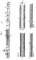
- Figure 1 is a schematic drawing of a foam core board lamination system.
- Figure 2 is a cross-sectional view of a foam core board with top and bottom facing materials showing the board's cell structure.
- Figure 3 is a cross-sectional view of a foam board showing the board skived through the center thereof.
- Figure 4 is a cross-sectional view of a foam board panel having interface material applied thereto.
- Figure 5 is a cross-sectional view of a foam board panel having decorative covering material applied thereto.
- Figure 6 is a schematic view of a foam board panel about to be inserted into a mold.
- Figure 7 is a schematic view of a foam core board panel as molded and located within a mold in the closed position.
- Figure 8 is a cross-sectional view of a contoured vehicle trim panel.
- The invention herein will be described with reference to a specific lamination system for manufacturing foam core boards. It is understood that other methods of manufacturing foam core boards wherein the size of the board in the thickness direction is constrained would likewise create boards having similar cell structure to that shown herein.
- It is further to be understood that although the herein invention is described with particular reference to foam core boards made utilizing polyurethane foam material that any chemical composition appropriately formed would serve the same function.
- Referring to Figure 1, there may be seen a foam
board lamination system 10. This system includesbottom facing material 14 and top facingmaterial 12 which are unrolled and passed through a conveyor system. The conveyor system includestop platen conveyor 20 and bottom platen conveyor 22 which collectively define therebetween the thickness to which the foam material may expand. Foamchemical dispenser 16 is shown located to dispense chemical material such as polyurethane foam material onto the top of the bottom facing material. This bottom facing material carries the foam material into the area between the conveyors such that the foam material is contained between the bottom facing material supported by the bottom platen conveyor and the top facing material supported by the top platen conveyor.Foam material 30, as shown, expands and occupies the entire space therebetween. Once the foam material expands, a board consisting of foam material and the two facing materials exits from the conveyor portion. Edgetrimmer 32 is provided to trim the edges of the board as it travels through the system.Horizontal splitter 34 is located to skive the board into multiple foam board panels.Cutoff mechanism 36 cuts the boards into selected lengths depending upon the desired end use. At the end of the lamination system there may be seenfoam board panels - A normal sequence for this type of operation includes presetting the distance between the upper and lower conveyor platens to twice the desired finished product thickness to be maintained. This equipment may typically have the capability of controlling panel thickness with excellent uniformity for panels between 2.54 mm (one tenth of an inch) to 88.9 mm (three and one half inches) thick.
- The top facing material and bottom facing material, as referenced, may be paper, plastic films, natural or synthetic woven or nonwoven fabrics, fiberglass mats, and/or composites thereof. The temperature to be maintained on the conveyor platens is set to achieve the desired foam core depending on the composition used. The chemical material to make up the foam is typically dispensed in a uniform manner across the width of the bottom facing material prior to entering the conveyors.
- Once the
foam board panels - Referring now to Figure 2, there may be seen a cross-sectional view of a typical foam board prior to passing through horizontal splitter. The
foam material 30 is shown havingbottom facing material 14 andtop facing material 12 on the peripheries thereof. It may be seen that the cell structure adjacent the surfaces of the foam board is relatively small causing the material to be denser in this area. Additionally, it may be seen that the cell structure at the center portion of the foam material is relatively large causing the board to be less dense in the center portion. - Figure 3 is identical to Figure 2, but shows the foam material after it is passed through
horizontal splitters 34. In Figure 3, it may be seen thatfoam board panels 40 on the bottom and 42 on the top have been formed andslot 32 is provided therebetween. Additionally, it is seen that when the skiving process occurs, the horizontal splitter acts to open the large cells at the interface of the slot formed by the skiving process. It may also be seen that two identical foam board panels are formed by the skiving process each having a facing material on the exterior and each having an opposite surface with large cellular structure and with many open cells having enhanced sound absorption characteristics. - Figure 4 shows
foam board panel 40 havinginterface material 44 laminated to the large cell surface thereof. The purpose of this interface material may be merely to add strength to the board. - Figure 5 shows
foam board panel 40 havingdecorative covering material 46 secured or laminated to the large cell structure portion of the board. This decorative material may be sufficiently porous or sufficiently flexible to allow sound energy to be transmitted therethrough such that sound energy may be absorbed within the large open cells adjacent thereto. In a vehicle trim panel, this decorative covering material may be fabric or some other material as may be aesthetically pleasing to an occupant of a motor vehicle. This decorative covering may be applied to the core board prior to, during or after molding. - Referring now to Figures 6-8, there is a simple description of the molding process to manufacture a contoured vehicle trim panel from
board panel 40. In Figure 6, there may be seen that a preheatedfoam board panel 40 is placed between the top portion ofmold 50 and the bottom portion ofmold 52.Bottom facing material 14 anddecorative layer material 46 is shown on either side offoam board panel 40 prior to molding process. - Figure 7 shows the foam board panel secured between the top and bottom portions of the mold with the mold being in the closed position. Figure 8 shows contoured vehicle
trim panel 60 molded to the desired end configuration. - Producing semirigid polyurethane foam core panels using the method herein described offers both improved acoustical charateristics and potential economic efficiencies. The improved acoustical characteristics are obtained by the splitting of the foam core board to open additional foam cells as the board is split through the composite structure at a point where the foam is in greatest uniformity and least densified. By the utilization of this skived surface as the cosmetic side of the product, an improved acoustical characteristic can be obtained. Improved economics are achieved through the initial lamination operation by producing a foam core board of double thickness and splitting said board to obtain two individual foam core boards at the end of the process.
Claims (9)
- A method of manufacturing a foam core panel having improved sound absorption characteristics said panel having a non uniform cellular structure such that the panel has a large cell structure at a center portion and a smaller cell structure at the top and bottom portion of the panel, the foam panel being formed between a top means (20) and a bottom means (22) which dimensionally limit the thickness of the panel, providing a bottom facing material (14), providing a top facing material (12), dispensing a foam chemical (30) to be located between the top facing material (14) and the bottom facing material (12) onto the bottom facing material (12), allowing the foam chemical material to expand while contained between the top facing material (14) and the bottom facing material (12), said top means (20) limiting the upward expansion and said bottom means (22) limiting the downward expansion, characterized in that the foam panel is skived through the center portion having the large cell structure to make two panels each having an exterior surface that has a large cell structure and has open cells to thereby improving the panels sound absorption characteristics.
- The method according to claim 1 characterized in that the step of skiving further comprises skiving the foam panel to form two panels (40,42) of identical dimension each having one surface of high density, small cell structure and each having one surface of low density, large cell structure.
- Method according to claim 1 wherein the foam core panel is a vehicle trim panel characterized in comprising the additional step of laminating a decorative covering (44;46) to the surface with the open cells on each panel, said covering (44;46) allowing sound energy to pass therethrough to be absorbed within the open cells of the panel.
- The method according to claim 3 characterized in further comprising the step of molding the panel with the decorative covering (44;46) to the desired end configuration.
- A vehicle trim panel having improved sound absorption characteristics obtained by the method of claims 1-4 characterized in that it comprises:
a foam core (30) of varying density, said core having one surface of high density and a small cell structure and a second skived surface of low density and large cell structure, said cell structure at the skived surface further including numerous open cells to promote sound absorption; and
a decorative layer (44;46) placed over the skived surface, said layer allowing sound energy to pass therethrough for absorption within the open cells of the foam core. - The vehicle trim panel according to claim 5 characterized in further comprising:
a facing material (14) secured to the opposite side of the foam core from the decorative layer (44;46). - The vehicle trim panel according to claim 5 characterized in that said foam core (30) and decorative layer (44;46) are arranged in a predetermined configuration, said configuration having been determined by a molding process.
- The vehicle trim panel according to claim 7 characterized in that the trim panel is a motor vehicle headliner.
- The vehicle trim panel according to claim 7 characterized in that the trim panel is an interior panel of a motor vehicle.
Applications Claiming Priority (2)
| Application Number | Priority Date | Filing Date | Title |
|---|---|---|---|
| US07/034,457 US4781774A (en) | 1987-04-06 | 1987-04-06 | Method of manufacturing foam core panels for sound absorption |
| US34457 | 1987-04-06 |
Publications (3)
| Publication Number | Publication Date |
|---|---|
| EP0286571A2 EP0286571A2 (en) | 1988-10-12 |
| EP0286571A3 EP0286571A3 (en) | 1991-07-24 |
| EP0286571B1 true EP0286571B1 (en) | 1994-12-07 |
Family
ID=21876547
Family Applications (1)
| Application Number | Title | Priority Date | Filing Date |
|---|---|---|---|
| EP88630060A Expired - Lifetime EP0286571B1 (en) | 1987-04-06 | 1988-04-05 | Improved sound absorption in foam core panels and their method of manufacture |
Country Status (4)
| Country | Link |
|---|---|
| US (1) | US4781774A (en) |
| EP (1) | EP0286571B1 (en) |
| CA (1) | CA1294302C (en) |
| DE (1) | DE3852334T2 (en) |
Families Citing this family (27)
| Publication number | Priority date | Publication date | Assignee | Title |
|---|---|---|---|---|
| GB8823528D0 (en) * | 1988-10-06 | 1988-11-16 | Arco Chem Co | Substantially closed cell rigid polyurethane foams |
| US4973376A (en) * | 1989-07-28 | 1990-11-27 | Chiu Ou Y | Method for manufacturing air-pervious insole |
| JPH0579508A (en) * | 1991-09-19 | 1993-03-30 | Sanpack:Kk | Roll |
| US5273698A (en) * | 1992-05-28 | 1993-12-28 | Creme Art Corporation | Method for shaping cover materials |
| US5296182A (en) * | 1992-05-28 | 1994-03-22 | Creme Art Corporation | Method for making formed laminate |
| EP0825001A1 (en) * | 1996-08-22 | 1998-02-25 | KROTSENG, Kathryn G. | Silicone foam molding process |
| US6180035B1 (en) * | 1999-05-04 | 2001-01-30 | Ming-Ti Hsieh | Scouring pad fabricating method |
| DE19922065A1 (en) * | 1999-05-14 | 2000-11-16 | Groene Horst Ditmar | Film, eg for packing foods, comprises an open pored hardened foam structure with a liq in the pores, and a pore size that increases with distance from the surface. |
| US7083849B1 (en) * | 1999-06-04 | 2006-08-01 | 3M Innovative Properties Company | Breathable polymer foams |
| DE19949643C2 (en) * | 1999-10-14 | 2003-04-30 | Johnson Controls Headliner | Process for manufacturing roof reinforcement for vehicles and roof reinforcement |
| JP4078411B2 (en) * | 2000-08-29 | 2008-04-23 | ニチアス株式会社 | Soundproof cover for automobile engine and method for producing foam material for soundproof cover |
| US7244489B2 (en) * | 2003-05-12 | 2007-07-17 | Cryovac, Inc. | Foamed article with absorbing characteristics on one side and non-absorbing characteristics on the other side and method for producing same |
| US7585559B2 (en) * | 2003-06-03 | 2009-09-08 | Intellectual Property Holdings, Llc | Foam barrier heat shield |
| US20060029788A1 (en) * | 2004-08-04 | 2006-02-09 | Foamex L.P. | Lower density, thermoformable, sound absorbing polyurethane foams |
| US20060065481A1 (en) * | 2004-09-24 | 2006-03-30 | Lear Corporation | Perforated hard trim for sound absorption |
| US7389802B2 (en) * | 2004-12-30 | 2008-06-24 | The Goodyear Tire & Rubber Co. | Tire with double layer innerliner |
| US7748184B1 (en) | 2005-02-09 | 2010-07-06 | Intellectual Property Holdings, Llc | Body panel having improved stiffness and method of making |
| DE102005031969A1 (en) * | 2005-07-08 | 2007-01-11 | Rehau Ag + Co. | Air guide element for motor vehicles and kit consisting thereof |
| JP5204754B2 (en) * | 2006-03-24 | 2013-06-05 | ハンツマン・インターナショナル・エルエルシー | Method for producing polyurethane foam |
| US20150343965A1 (en) * | 2014-06-02 | 2015-12-03 | Ford Global Technologies, Llc | Truck cab liner with noise absorber |
| TWI684543B (en) * | 2015-04-23 | 2020-02-11 | 維樂工業股份有限公司 | Manufacturing method of bicycle seat cushion |
| TWI565617B (en) | 2015-08-03 | 2017-01-11 | Bicycle seat cushion body with auxiliary function sheet and manufacturing method thereof | |
| US10279515B2 (en) * | 2016-02-18 | 2019-05-07 | Covestro Llc | Processes for producing flexible polyurethane foam laminates and laminates produced thereby |
| CN107584778B (en) * | 2016-07-08 | 2019-04-30 | 苏州康丽达精密电子有限公司 | Using the moulding process of the conducting foam of concave-convex Mylar |
| US10525643B2 (en) * | 2017-05-03 | 2020-01-07 | Covestro Llc | Methods for making foam laminates having a concave surface and laminates produced thereby |
| US11332590B2 (en) | 2019-11-28 | 2022-05-17 | Sekisui Voltek, Llc | Crosslinked polyolefin foam having large core cells |
| US20210163705A1 (en) * | 2019-11-28 | 2021-06-03 | Sekisui Voltek, Llc | Split crosslinked polyolefin foam composition and method |
Family Cites Families (9)
| Publication number | Priority date | Publication date | Assignee | Title |
|---|---|---|---|---|
| GB738494A (en) * | 1951-07-07 | 1955-10-12 | Scholl Mfg Co Ltd | Laminated material with gripping face and method of making the same |
| US2891288A (en) * | 1951-09-04 | 1959-06-23 | Goodrich Co B F | Adhesive absorptive weather strip and method of making |
| FR1541044A (en) * | 1967-08-09 | 1968-10-04 | Monsanto Co | Thermoplastic foam for sound dampening |
| US4042745A (en) * | 1976-07-14 | 1977-08-16 | Cornwell Charles E | Cementitious sound absorbing panels and sound absorbing sprayed wall structures |
| US4283457A (en) * | 1979-11-05 | 1981-08-11 | Huyck Corporation | Laminate structures for acoustical applications and method of making them |
| DE3151296A1 (en) * | 1981-12-24 | 1983-07-14 | C.A. Greiner und Söhne GmbH & Co KG, 7440 Nürtingen | Process for producing a three-dimensionally permanently shaped sound-absorbing composite mat and sound-absorbing composite mat produced thereby |
| DE3220023C2 (en) * | 1982-05-27 | 1993-05-27 | Cellofoam Deutschland Gmbh, 7950 Biberach | Sound-absorbing flow channel and method for its manufacture |
| IT1159050B (en) * | 1983-08-02 | 1987-02-25 | Pianfei Ipa Spa | PROCEDURE FOR THE MANUFACTURE OF SELF-SUPPORTING PRINTABLE PANELS PARTICULARLY PREFORMED PANELS FOR INTERIOR INSTALLATIONS OF MOTOR VEHICLES AND PRODUCT OBTAINED WITH THIS PROCEDURE |
| DE3614879A1 (en) * | 1986-05-02 | 1987-11-05 | Hennecke Gmbh Maschf | METHOD AND DOUBLE CONVEYOR BELT FOR THE PRODUCTION OF FOAM MATERIAL LINES PROVIDED WITH COATING LAYERS FROM A FLOWABLE REACTION MIXTURE |
-
1987
- 1987-04-06 US US07/034,457 patent/US4781774A/en not_active Expired - Fee Related
-
1988
- 1988-04-05 EP EP88630060A patent/EP0286571B1/en not_active Expired - Lifetime
- 1988-04-05 CA CA000563271A patent/CA1294302C/en not_active Expired - Lifetime
- 1988-04-05 DE DE3852334T patent/DE3852334T2/en not_active Expired - Fee Related
Also Published As
| Publication number | Publication date |
|---|---|
| DE3852334T2 (en) | 1995-04-20 |
| CA1294302C (en) | 1992-01-14 |
| EP0286571A3 (en) | 1991-07-24 |
| US4781774A (en) | 1988-11-01 |
| DE3852334D1 (en) | 1995-01-19 |
| EP0286571A2 (en) | 1988-10-12 |
Similar Documents
| Publication | Publication Date | Title |
|---|---|---|
| EP0286571B1 (en) | Improved sound absorption in foam core panels and their method of manufacture | |
| US4863791A (en) | Sound absorption in foam core panels | |
| US4211590A (en) | Method of making perforated contoured trim panel | |
| US5049439A (en) | Thermoformable article | |
| GB2067460A (en) | Shaping foam slabs | |
| JPH0528179B2 (en) | ||
| US3819781A (en) | Textured surface,cellular core sheet material | |
| JPS6327171B2 (en) | ||
| EP0137125A2 (en) | Method of manufacturing mouldable self-supporting panels, in particular preformed panels for motorvehicle interior finishing, and product obtained thereby | |
| CN209888317U (en) | Trunk cover plate | |
| JPH0534278Y2 (en) | ||
| JPH05229367A (en) | Instrument panel and its manufacture | |
| JPS6345286B2 (en) | ||
| JPS63162350A (en) | Carpet for automobile | |
| JPH0745133B2 (en) | Molded interior material manufacturing method | |
| JPH0229007B2 (en) | ||
| JPH0474182B2 (en) | ||
| KR920003234B1 (en) | Vehicle mat | |
| JPH0534277Y2 (en) | ||
| JPH0618722B2 (en) | Method for manufacturing laminated interior material | |
| JPS63269749A (en) | Automobile ceiling material and its manufacture | |
| JPH0952305A (en) | Laminate for forming and formed body | |
| JP2833316B2 (en) | Composite and method for producing the same | |
| JPH0482950A (en) | Production of lightweight structural material | |
| JPS6345287B2 (en) |
Legal Events
| Date | Code | Title | Description |
|---|---|---|---|
| PUAI | Public reference made under article 153(3) epc to a published international application that has entered the european phase |
Free format text: ORIGINAL CODE: 0009012 |
|
| AK | Designated contracting states |
Kind code of ref document: A2 Designated state(s): DE FR GB IT |
|
| PUAL | Search report despatched |
Free format text: ORIGINAL CODE: 0009013 |
|
| AK | Designated contracting states |
Kind code of ref document: A3 Designated state(s): DE FR GB IT |
|
| 17P | Request for examination filed |
Effective date: 19920113 |
|
| 17Q | First examination report despatched |
Effective date: 19930318 |
|
| GRAA | (expected) grant |
Free format text: ORIGINAL CODE: 0009210 |
|
| AK | Designated contracting states |
Kind code of ref document: B1 Designated state(s): DE FR GB IT |
|
| ET | Fr: translation filed | ||
| REF | Corresponds to: |
Ref document number: 3852334 Country of ref document: DE Date of ref document: 19950119 |
|
| ITF | It: translation for a ep patent filed |
Owner name: UFFICIO BREVETTI RICCARDI & C. |
|
| PG25 | Lapsed in a contracting state [announced via postgrant information from national office to epo] |
Ref country code: GB Effective date: 19950405 |
|
| PLBE | No opposition filed within time limit |
Free format text: ORIGINAL CODE: 0009261 |
|
| STAA | Information on the status of an ep patent application or granted ep patent |
Free format text: STATUS: NO OPPOSITION FILED WITHIN TIME LIMIT |
|
| 26N | No opposition filed | ||
| GBPC | Gb: european patent ceased through non-payment of renewal fee |
Effective date: 19950405 |
|
| PG25 | Lapsed in a contracting state [announced via postgrant information from national office to epo] |
Ref country code: FR Effective date: 19951229 |
|
| PG25 | Lapsed in a contracting state [announced via postgrant information from national office to epo] |
Ref country code: DE Effective date: 19960103 |
|
| REG | Reference to a national code |
Ref country code: FR Ref legal event code: ST |
|
| PG25 | Lapsed in a contracting state [announced via postgrant information from national office to epo] |
Ref country code: IT Free format text: LAPSE BECAUSE OF NON-PAYMENT OF DUE FEES;WARNING: LAPSES OF ITALIAN PATENTS WITH EFFECTIVE DATE BEFORE 2007 MAY HAVE OCCURRED AT ANY TIME BEFORE 2007. THE CORRECT EFFECTIVE DATE MAY BE DIFFERENT FROM THE ONE RECORDED. Effective date: 20050405 |