EP0286432A2 - Relay - Google Patents
Relay Download PDFInfo
- Publication number
- EP0286432A2 EP0286432A2 EP88303171A EP88303171A EP0286432A2 EP 0286432 A2 EP0286432 A2 EP 0286432A2 EP 88303171 A EP88303171 A EP 88303171A EP 88303171 A EP88303171 A EP 88303171A EP 0286432 A2 EP0286432 A2 EP 0286432A2
- Authority
- EP
- European Patent Office
- Prior art keywords
- armature
- core
- assembly
- bobbin
- lever
- Prior art date
- Legal status (The legal status is an assumption and is not a legal conclusion. Google has not performed a legal analysis and makes no representation as to the accuracy of the status listed.)
- Withdrawn
Links
Images


Classifications
-
- H—ELECTRICITY
- H01—ELECTRIC ELEMENTS
- H01H—ELECTRIC SWITCHES; RELAYS; SELECTORS; EMERGENCY PROTECTIVE DEVICES
- H01H50/00—Details of electromagnetic relays
- H01H50/02—Bases; Casings; Covers
- H01H50/04—Mounting complete relay or separate parts of relay on a base or inside a case
- H01H50/041—Details concerning assembly of relays
- H01H50/042—Different parts are assembled by insertion without extra mounting facilities like screws, in an isolated mounting part, e.g. stack mounting on a coil-support
-
- H—ELECTRICITY
- H01—ELECTRIC ELEMENTS
- H01H—ELECTRIC SWITCHES; RELAYS; SELECTORS; EMERGENCY PROTECTIVE DEVICES
- H01H50/00—Details of electromagnetic relays
- H01H50/16—Magnetic circuit arrangements
- H01H50/18—Movable parts of magnetic circuits, e.g. armature
- H01H50/24—Parts rotatable or rockable outside coil
-
- H—ELECTRICITY
- H01—ELECTRIC ELEMENTS
- H01H—ELECTRIC SWITCHES; RELAYS; SELECTORS; EMERGENCY PROTECTIVE DEVICES
- H01H50/00—Details of electromagnetic relays
- H01H50/02—Bases; Casings; Covers
- H01H2050/028—Means to improve the overall withstanding voltage, e.g. creepage distances
-
- H—ELECTRICITY
- H01—ELECTRIC ELEMENTS
- H01H—ELECTRIC SWITCHES; RELAYS; SELECTORS; EMERGENCY PROTECTIVE DEVICES
- H01H50/00—Details of electromagnetic relays
- H01H50/16—Magnetic circuit arrangements
- H01H50/36—Stationary parts of magnetic circuit, e.g. yoke
- H01H2050/365—Stationary parts of magnetic circuit, e.g. yoke formed from a single sheet of magnetic material by punching, bending, plying
Definitions
- the present invention relates to relays in particularly but not exclusively to relays suitable for use in residual current circuit breakers (RCCB) devices.
- RRCB residual current circuit breakers
- RCCB devices need to be capable of indicating whether the contacts are open or closed and conveniently a relay for use in such devices includes a mechanism for indicating its state.
- a relay suitable for the use in a residual current circuit breaker device comprises a bobbin assembly formed from electrically insulating and non-magnetic material which includes a central passage for a magnetic core and provides an integral mounting for fixed contacts and coil tags, and a one piece core and field piece assembly which provides a support for an armature carrying the moving contact of the relay and which is securable to the bobbin assembly after the core has been fitted in the central passage therein.
- the core may be secured within the bobbin as by a friction fit, a bayonet fitting, a screw thread or by means of an adhesive.
- the core protrudes axially beyond the bobbin and is held in place by means of a spring washer secured over the protruding end of the core.
- the bobbin assembly is moulded from a plastics material.
- the core and field piece are formed from a sheet of ferrous material as by stamping and forming.
- the armature is conveniently also formed from ferrous material which is secured to a platform of electrically insulating material on which electrically conductive springs are mounted carrying at their ends the movable contacts, and conveniently is adapted to pivot about an upper edge of the field piece remote from the fixed contacts.
- the core and field piece assembly comprises a cylindrical core which extends integrally from and at one end of a base, the opposite end of which is bent upwardly parallel to the core the upper edge of the bent-up end forming the pivot for the armature, and the height of the core is made the same as the height of the pivot above the base, so that when the armature is fitted to the assembly, the armature is parallel to the base when in contact with the pivot and the core.
- the height of the fixed contacts above the base from which the core extends can be controlled very accurately and will be governed largely by the tolerance of the moulding operation from which the bobbin assembly is formed. Since the core and field piece assembly can also be fabricated accurately using a jig, the top of the core and the armature pivot can be controlled so as to be a constant distance (measured perpendicularly) from the fixed relay contacts. Since the armature assembly can also be manufactured very accurately by employing plastics injection moulding techniques to form the insulating bridge and controlling carefully the dimensions of the metallic parts, so little or no adjustment of the moving contacts is required after the final assembly of the armature to the remainder of the relay assembly.
- the bobbin assembly conveniently includes an abutment which cooperates with the armature assembly to prevent the latter from pivoting more than a certain distance away from the core.
- the armature assembly must of course be located below this abutment during assembly.
- the fixed contacts are preferably separated by means of a thin partition of electrically insulating material and conveniently the armature restraining abutment is provided by way of an undercut in this partition so as to define an overhanging section below which the armature will normally sit.
- a return spring is conveniently located between a lug extending rearwardly from the armature and a similar lug extending rearwardly from the bent up part of the base of the integral core and field piece assembly.
- armature travel towards the core in the form of a rectangular frame spring held captive between the two abutments by means of a helical extension spring placed over the two abutments after the frame spring.
- the abutments are waisted and the opposite ends of the return spring are restrained from sliding off the abutments by the shoulders of the outboard end of each waisted section of each abutment.
- a lock out lever is provided as part of the relay assembly which can occupy two positions, a first position in which a part of the lever protrudes between the armature and the bobbin assembly to prevent the armature from moving towards the core and a second position in which the protruding part of the lever is withdrawn conpletely from between the armature and the bobbin assembly to allow the armature to move towards the core when the coil is energised.
- the lever is mounted on the bobbin assembly and is pivotable about an upstanding pivot pin itself moulded integrally with the bobbin assembly.
- a return spring is provided urging the lever into the first position in which it prevents movement of the armature towards the core and the remote end of the arm is preferably adapted for engagement by a movable element of a reset mechanism which may be carried by the relay or within a housing of an appliance of which the relay forms a part, so that the lever is moved into its disengaging position only in response to a positive resetting of the mechanism.
- the resetting action may be associated with the insertion or removal of a component such as a plug.
- the lever conveniently includes a lateral abutment at the end which is to cooperate with the armature and pivoting of the lever to inhibit movement of the armature involves the insertion of the abutment between the armature and the bobbin assembly and in this event, preferably the lever is bent in the region of the pivot point so that the end of the lever remote from the abutment does not interfere with the armature when the opposite end containing the abutment has been moved clear of the armature.
- the pin on which the lever pivots protrudes upwardly beyond the lever to provide a support for a torsion spring one end of which extends along the lever to terminate in the region of the end of the lever which is movable into and out of the path of the armature and the other end of which is held captive in an aperture in the pivot pin.
- the aperture may be a hole drilled or otherwise formed dimetrically through the pin or may be in the form of a slot at the upper end of the pin.
- the end of the spring held captive therein may be secured in position by means of an adhesive or the material of the pin selected to be sufficiently resilient and the relative sizes of the slot and the spring material are such that the end of the spring is resiliently held in position.
- the spring can serve as a means for retaining the lever on the pin.
- the pin may be formed with an enlarged head to hold the lever and spring captive therebelow.
- the lever only protrudes under one edge of the armature, it may be possible for the armature to distort and tilt laterally about its pivot axis so that one pair of contacts make, even if the pair are prevented from coming into contact.
- the abutment at the end of the lever may be extended so as to protrude across below the armature so as to fit below both edges of the armature.
- the extended part may also be provided with an abutment at its end remote from the first abutment, the distance between the two abutments being just equal to the width of the armature assembly, and the armature is either cut away or shaped and dimensioned in such a way that the extension and the remote abutment are clear of or accommodated below, the armature and do not prevent the armature from closing when the lever has been moved out of the said first position.
- an indicator flag may be mounted on the armature assembly so as to move therewith.
- the indicator flag may be positioned at the end of a lever arm which itself extends from the armature in the general direction away from the pivot axis of the armature.
- the indicator flag may comprise a plate, half of which is coloured in one colour and the other half is coloured in a different colour, and the relay is mounted relative to a viewing window which is dimensioned such that when the relay is energised, one of the coloured regions is visible through the window and when the relay is de-energised, the other coloured region is visible.
- a retaining member may also be secured between the two rearward protrusions before the return spring is fitted.
- lock out lever is to be employed, this is preferably mounted on the upper flange of the bobbin before the armature is fitted.
- the fabrication of the relay does not require any setting up and careful adjustment of the spring sets arms on which the movable contacts are carried to adjust the spacing between the movable and fixed contacts.
- a guide may be formed by means of a window in the upper flange of the bobbin immediately below the end of the lock-out lever which is to be actuated by the mechanical interlock mechanism, to provide a guide for the member engaging the said end of the lever.
- flash over between contacts may be further prevented by providing a thin wall of electrically insulating material between the moving contacts.
- the engagement between the armature assembly and the excess travel abutment on the bobbin assembly may be effected by means of a protrusion of the ferrous part of the armature or a protrusion of the electrically insulating bridge material or protrusions from both parts.
- the ferrous part of the armature may be in the form of a flat plate but if the core is in the form of a hollow tubular member, the armature plate may include a perpendicular protrusion of ferrous material which during assembly is caused to enter the upper open end of the core. The resulting device is formed to require less current to achieve the same magnetic pull on the amature assembly.
- the relay comprises a magnetic circuit consisting of a core 3 a field piece 1 and an armature 2.
- the core is turned from a solid rod or stamped from sheet and attached to the field piece by rivetting, moulding or any other method.
- Coil 11 is wound upon a separate bobbin 12.
- Armature 2 carries one or more moving contact blade assemblies 6 mounted in place by means of cooperating mouldings 7 and 8 clamped to armature 2 by a rivet 9.
- contact and blade assemblies 6 can be moulded into a single insulating mount for mounting upon armature 2.
- the moving contact blade assemblies 6 cooperate with one or more fixed blade contact assemblies 5 fitted into insulated base 4, mounted upon field piece 1, by screws or rivets.
- Armature 2 hinges upon nose 1A of a field piece 1 and is retained in the position shown by coild spring 15 when coil 11 is not energised.
- the relay may be mounted by means of a screw 10 engaging in a tapped hole in core 3 or by screws through other parts of the assembly.
- the relay described comprises a large number of separate piece parts requiring a large number of separate operations in the course of assembly and after assembly, the relay must be set manually. "Make" contact over-travel is determined by adjustment of base 4 on field piece 1, thereby adjusting the position of fixed blade contact assembly 5 relative to moving blade contact assembly 6.
- the contact gap/armature movement is restricted by the moving blade contact assembly 6 backing onto stop 13 in base 4 which must be adjusted, or by the provision of a tonge 14 on armature 2 to act as a stop against field piece 1.
- relays to be described with reference to Figure 2 onwards is especially suitable for use in an RCCB, the invention is not limited to this application and may be used in the construction of any relay having normally open contacts.
- the relay includes a bobbin 21 on which a coil 20 is wound shown in cross section in Figure 2.
- a magnetic circuit comprising core 22 formed integrally with field piece 23 from a stamping of mild steel of the form shown in Figure 4.
- Bobbin 21 is moulded of a suitable plastics material in one piece with an upper flange formed with a parallel sided tray 24 with fixed contact assemblies 25 at one end and coil tags 26 at its opposite end.
- Armature assembly 27 comprises a mild steel armature plate 28 (which forms part of the magnetic circuit of the relay when fitted) and a moulded plastic contact carrier 29 shaped to straddle the armature 28 in the form of a bridge and to be attached to it by integral plastic pillars 30 (see Figure 3) which can be peened over on the underside as in the form of rivets.
- the moving contacts are fitted at the ends of blades or springs 31, typically of copper strip, and these are mounted on the upper surface of the carrier or bridge 29 also by means of integral plastic pillars 32 which can be peened over to secure the springs in position.
- the armature plate and the springs may be secured to the moulded plastics bridge 29 by heat staking and/or ultrasonic welding. Alternatively or in addition an adhesive may be employed.
- the bridge assembly 29 surrounds the armature plate 28 on three sides to maximise creepage distance between the current carrying springs 31 and the conductive ferrous armature plate 28.
- Armature assembly 27 is hinged upon the upstanding part of field piece 23 with retainer clip 33 and coil spring 34 located around tonges 35 and 36 protruding from the rear of the armature plate 28 and the field piece 23 respectively.
- Spring 34 serves to mechanically biase the armature assembly 27 into the open contact position in the absence of energising current. Retaining clip 33 prevents armature 28 from becoming unseated from field piece 23 in the event of the relay being subjected to excessive mechanical shock.
- Bobbin 21 together with base assembly 24 is locked into position on core 22 by a retaining ring or spring washer 37.
- the ring or spring washer 37 may be replaced by a copper shading ring to which end a diametrical slot is required in the upper end of the core 22, as illustrated by 39 in Figure 2.
- lugs 42 forming extensions of the field piece 23 may engage in slots in the remainder of the equipment and be clamped in place.
- This construction allows a short assembly time and minimises or eliminates adjustment following assembly.
- Figure 5 illustrates the relay assembly of the preceding Figures 2 to 4 with certain modifications. These enable the relay to be connected with the two moving contacts as the live contacts.
- the screen 43 which includes the excess travel prevention nose 41, is thinned and a thin lateral flange 40 is provided forwardly of the bridge 29 to cooperate with the reduced section division 43 to more completely separate the two pairs of electrodes particularly during a breaking when flash over can occur.
- Figure 6 illustrates the coil and magnet sub-assembly of a modified form of relay constructed in accordance with the invention.
- the core and field piece is as shown in Figures 2 and 5 in which the core designated by reference numeral 22 and the upturn field piece is designated 46.
- the latter includes the abutment 36 for attachment to the lower end of this spring 34 (not shown in Figure 6) and the coil bobbin assembly (to be described) which differs from the coil bobbin assembly of Figures 2 and 5 is designated by reference numeral 48 to differentiate the two and this is secured in place by means of a spring washer 50 fitted over the protruding upper end of the core 22 after the coil bobbin has been fitted.
- the bobbin assembly 48 comprises as before a unitary plastics injection moulding but in this case the base 52 is generally rectangular and contains two downwardly protruding parallel runners one of which can be seen at 54 in Figure 6. A similar parallel runner (not visible in the drawings) is provided on the opposite side of the base on the underside thereof
- the runners provide a means by which the relay can be mounted in other equipment.
- the upper tray section 56 of the plastics injection moulding includes a integral lateral flange 58 having an upstanding pin 60 preferably moulded therein during manufacture and a rectangular guide window 62 for the purpose of which will be described later.
- a lever (to be described in relation to Figure 7) is pivotally mounted on the pin 60 for engagement with the armature (not shown in Figure 6) to prevent the latter from closing into the contact closed position when it is desired to "lock out” the relay to prevent operation during a fault condition.
- Figure 7 is a plan view of the assembly of Figure 6 with the lock out lever in position.
- the latter comprises a hub 64, which is apertured to fit over the pin 60, an elongated arm 66 having a lateral abutment 68 for engaging below the armature (not shown in Figure 7) at the remote end of the arm 66 and an actuating arm 70 having an inclined surface 72 for engagement by an actuator (to be described) for urging the lever in an anticlockwise direction about the pivot from the position shown in Figure 7 to the position shown in Figure 8.
- the action of the spring 74 is to return the lever to the position shown in Figure 7 in the event that any actuating force on the inclined surface 72 has been removed.
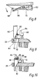
- Figures 9 and 10 show how the lever can be actuated by means of the downward movement of an actuating member 80 having a cooperating inclined surface 82 for engaging with the inclined surface 72 on the actuating arm 70 of the lever.
- the actuator 80 is shown in its raised position in which a thin leading tonge 84 remains engaged in the window 62 (simply to guide the actuator 80 at all times) and in Figure 10 the actuator is shown in its lowered and fully actuated position in which the interengagement between the two inclined surfaces 72 and 82 (which comprise ramps) has forced the lever in an anticlockwise direction (as viewed in Figure 6) to occupy the position shown in Figure 8.
- the actuator 80 is at all tines engaged within the window 62 even when in its raised position in which the thin tonge 84 determines the stop position of the actuating arm 70 of the lever.
- the abutment 68 includes an upstanding stop 84 and the dimensions of the latter and the height of the abutment 68 are such that whilst the latter can protrude below the armature when the latter is in its raised position, the upstanding stop 84 cannot. The latter thus will engage against the side edge of the armature when the latter is in its raised condition preventing excessive rotation of the lever under the action of the spring 74.
- the abutment 68 sits squarely below the left-hand edge of the armature (see Figure 11) and the upstanding stop 84 is just clear of the armature.
- the upper end of the pin 60 may be formed into a dome 86 and Figure 10 also shows the slot 88 into which the shorter tang 78 of the spring 74 fits.
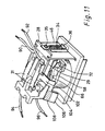
- Figure 11 shows the assembled relay with the armature assembly in position.
- the latter is substantially as shown in Figures 2 and 5 and is pivotally fitted to the upper end of the upstanding section 46 of the field piece in the manner described with reference to Figures 2 and 5 by means of the return spring 34 fitted between the abutment 36 on the field piece and the abutment 35 at the rear of the armature plate 28.
- Leads 90 and 92 are shown electrically connected as by soldering or brazing to the rear ends of the springs 31 and two further leads 94 and 96 are connected at their inboard ends to the two conductive tags 98 and 100 respectively, extending from the fixed contact 25 and best seen in Figure 7.
- the relay is shown with the armature in its raised position in Figure 11 and with the lock out arm shown in Figure 7 with the abutment 68 below the lower nearer edge of the armature.
- the armature assembly of Figure 11 is substantially shown in Figures 2 and 5 with a bridge of plastics material 29 covering the upper surface of the magnetic armature plate 28. It is therefore the edge of the plastics bridge under which the abutment 68 sits when the lever is in its position shown in Figure 11.
- Figure 11 illustrates a modification to the armature bridge assembly in the form of a lateral extension 102 which extends sufficiently to the side of the armature bridge 29 so as to clear the outer edge of the lateral extension 58 of the coil bobbin assembly at which stage the lateral extension is folded down and extends forwardly as an arm 104 to terminate in a spade like end 106 which forms an indicator.
- the spade like end 106 includes a coloured region 108 and the relay is mounted within a housing (not shown) so that half of the spade like end 106 can be seen through a window in the housing and either the coloured or the uncoloured region is visible through the window depending on whether the armature is in its raised position (in which case the uncoloured region is visible) or in its lowered actuated position (with the contacts closed) in which case the coloured region is visible through the window.
- a red colour is used for the coloured region 108 so as to denote that the unit has become "live” since the contacts are now closed.
- abutment 68 includes a very thin extension 110 which extends in an elongate manner below the armature to terminate in a second abutment 112 similar to the abutment 68. This is best seen in Figure 13 with reference to Figure 12 which is a cross section on the line 12 12 of Figure 13.
- the armature plate 28 is cut away to define a cavity 114 within the plastics bridge 29 so that the lever pivoted into an out of engagement position, the platform of the abutment 68 is clear of the edge 116 and the abutment 112 can enter the cavity 114 as the armature moves in a downward direction in the direction of the arrow 118 in Figure 12.
- Movement of the lever in the direction of the arrow 120 of Figure 13, causes a general lateral movement of the extension 110 in the direction of the arrow 122 in Figure 12, and with the armature in its raised position, the abutment 68 can move under the edge 116 on the one side of the armature and the abutment 112 under the edge 124 of the opposite side of the armature bridge 29 so that if the armature is then attracted towards the core due to inadvertent energisation of the coil, the armature is prevented from moving by both abutments. This prevents any possible engagement of one of the contact pairs due to pivoting of the armature plate in the direction of the arrow 126 (see Figure 12) which might otherwise result if only the abutment 68 is provided.
- the Thickness of the extension 110 is selected so that this does not interfere with the armature when the latter is in its lowered actuated position.
- relay shown in Figure 11 incorporates all the features of the invention namely a unitary coil bobbin assembly, a unitary core and field piece assembly secured to the bobbin assembly by a single fixing, a lock out lever mounted on the coil bobbin assembly and an indicator mounted directly on the armature assembly.
- the unitary construction and design of the coil bobbin assembly and the core and field piece assembly with the mounting of the fixed contacts on the coil bobbin eliminates the need for setting up the spring sets such as 31 after the armature assembly has been fitted to the subassembly of coil and field piece, since the height of the armature above the core and coil bobbin assembly is dictated by the engagement of the nose 41 with the abutment 40 (as described in relation to Figures 2 and 3), and the springs 31 can therefore be set in exactly the required position during manufacture so that the moving contacts are just the required height above the fixed contacts when the armature assembly is in its raised position relative to the core.
- the lowered position of the armature is dictated by the height of the core and the height of the upstanding part 46 of the field piece both of which can be controlled accurately during manufacture and controlled accurately relative to the position of the fixed contacts by relying on the manufacturing tolerances of the injection moulded plastics coil bobbin assembly which can only be fitted on the core and field piece in one way.
Landscapes
- Physics & Mathematics (AREA)
- Electromagnetism (AREA)
- Electromagnets (AREA)
Abstract
An electric relay which comprises the assembly of a bobbin assembly (21, 24) of electrically insulating and non-magnetic material which includes a central passage for a magnetic core (22) and an integral mounting for fixed contacts (25) and coil tags (26), coil carried by the assembly (21, 24) coaxially with the central passage, a unitary core and field piece assembly (22, 23) which is secured to the bobbin assembly by spring washer (37) with the core (22) extending through the central passage, and an armature (27) carrying the moving contacts (31) and which is pivotally supported on the field piece of the core and field piece assembly.
Description
- The present invention relates to relays in particularly but not exclusively to relays suitable for use in residual current circuit breakers (RCCB) devices.
- With the increasing use of RCCB devices with domestic and industrial mains power equipment there has become a requirement for simple reliable low cost relays able to perform to the necessary standards.
- Additionally a mechanical interlock must be provided to prevent the relay contacts being closed under certain conditions.
- In addition RCCB devices need to be capable of indicating whether the contacts are open or closed and conveniently a relay for use in such devices includes a mechanism for indicating its state.
- It is therefore an object of the present invention to provide an alternative and improved design of relay which can satisfy the above requirements.
- According to one aspect of the present invention a relay suitable for the use in a residual current circuit breaker device comprises a bobbin assembly formed from electrically insulating and non-magnetic material which includes a central passage for a magnetic core and provides an integral mounting for fixed contacts and coil tags, and a one piece core and field piece assembly which provides a support for an armature carrying the moving contact of the relay and which is securable to the bobbin assembly after the core has been fitted in the central passage therein.
- The core may be secured within the bobbin as by a friction fit, a bayonet fitting, a screw thread or by means of an adhesive.
- Preferably however the core protrudes axially beyond the bobbin and is held in place by means of a spring washer secured over the protruding end of the core.
- Preferably the bobbin assembly is moulded from a plastics material.
- Preferably the core and field piece are formed from a sheet of ferrous material as by stamping and forming.
- The armature is conveniently also formed from ferrous material which is secured to a platform of electrically insulating material on which electrically conductive springs are mounted carrying at their ends the movable contacts, and conveniently is adapted to pivot about an upper edge of the field piece remote from the fixed contacts.
- According to a preferred feature of the invention, the core and field piece assembly comprises a cylindrical core which extends integrally from and at one end of a base, the opposite end of which is bent upwardly parallel to the core the upper edge of the bent-up end forming the pivot for the armature, and the height of the core is made the same as the height of the pivot above the base, so that when the armature is fitted to the assembly, the armature is parallel to the base when in contact with the pivot and the core.
- It will be seen that by constructing a relay in this way, the height of the fixed contacts above the base from which the core extends can be controlled very accurately and will be governed largely by the tolerance of the moulding operation from which the bobbin assembly is formed. Since the core and field piece assembly can also be fabricated accurately using a jig, the top of the core and the armature pivot can be controlled so as to be a constant distance (measured perpendicularly) from the fixed relay contacts. Since the armature assembly can also be manufactured very accurately by employing plastics injection moulding techniques to form the insulating bridge and controlling carefully the dimensions of the metallic parts, so little or no adjustment of the moving contacts is required after the final assembly of the armature to the remainder of the relay assembly.
- It is of course important that the armature is prevented from moving too far away from the core to ensure attraction of the armature towards the core on energisation. To this end the bobbin assembly conveniently includes an abutment which cooperates with the armature assembly to prevent the latter from pivoting more than a certain distance away from the core. The armature assembly must of course be located below this abutment during assembly.
- Where two fixed contacts and two movable contacts are provided so that the relay can break both the live and the neutral lines in a supply, the fixed contacts are preferably separated by means of a thin partition of electrically insulating material and conveniently the armature restraining abutment is provided by way of an undercut in this partition so as to define an overhanging section below which the armature will normally sit.
- A return spring is conveniently located between a lug extending rearwardly from the armature and a similar lug extending rearwardly from the bent up part of the base of the integral core and field piece assembly.
- Conveniently a further restraint is provided limiting the armature travel towards the core in the form of a rectangular frame spring held captive between the two abutments by means of a helical extension spring placed over the two abutments after the frame spring.
- Preferably the abutments are waisted and the opposite ends of the return spring are restrained from sliding off the abutments by the shoulders of the outboard end of each waisted section of each abutment.
- According to another preferred feature of the invention, a lock out lever is provided as part of the relay assembly which can occupy two positions, a first position in which a part of the lever protrudes between the armature and the bobbin assembly to prevent the armature from moving towards the core and a second position in which the protruding part of the lever is withdrawn conpletely from between the armature and the bobbin assembly to allow the armature to move towards the core when the coil is energised.
- Preferably the lever is mounted on the bobbin assembly and is pivotable about an upstanding pivot pin itself moulded integrally with the bobbin assembly. Preferably a return spring is provided urging the lever into the first position in which it prevents movement of the armature towards the core and the remote end of the arm is preferably adapted for engagement by a movable element of a reset mechanism which may be carried by the relay or within a housing of an appliance of which the relay forms a part, so that the lever is moved into its disengaging position only in response to a positive resetting of the mechanism.
- The resetting action may be associated with the insertion or removal of a component such as a plug.
- According to a preferred feature of this aspect of the invention, the lever conveniently includes a lateral abutment at the end which is to cooperate with the armature and pivoting of the lever to inhibit movement of the armature involves the insertion of the abutment between the armature and the bobbin assembly and in this event, preferably the lever is bent in the region of the pivot point so that the end of the lever remote from the abutment does not interfere with the armature when the opposite end containing the abutment has been moved clear of the armature.
- Preferably the pin on which the lever pivots protrudes upwardly beyond the lever to provide a support for a torsion spring one end of which extends along the lever to terminate in the region of the end of the lever which is movable into and out of the path of the armature and the other end of which is held captive in an aperture in the pivot pin. The aperture may be a hole drilled or otherwise formed dimetrically through the pin or may be in the form of a slot at the upper end of the pin.
- Where a slot is utilised, the end of the spring held captive therein may be secured in position by means of an adhesive or the material of the pin selected to be sufficiently resilient and the relative sizes of the slot and the spring material are such that the end of the spring is resiliently held in position.
- It will be seen that the spring can serve as a means for retaining the lever on the pin. Alternatively or in addition the pin may be formed with an enlarged head to hold the lever and spring captive therebelow.
- It will be seen that where the lever only protrudes under one edge of the armature, it may be possible for the armature to distort and tilt laterally about its pivot axis so that one pair of contacts make, even if the pair are prevented from coming into contact. To avoid this, the abutment at the end of the lever may be extended so as to protrude across below the armature so as to fit below both edges of the armature. To this end the extended part may also be provided with an abutment at its end remote from the first abutment, the distance between the two abutments being just equal to the width of the armature assembly, and the armature is either cut away or shaped and dimensioned in such a way that the extension and the remote abutment are clear of or accommodated below, the armature and do not prevent the armature from closing when the lever has been moved out of the said first position.
- According to a further aspect of the invention, an indicator flag may be mounted on the armature assembly so as to move therewith. By arranging that the relay is mounted behind a panel containing a window through which the indicator flag can be viewed, so the state of the relay can be determined quickly by visual observation.
- In order to magnify the available movement, the indicator flag may be positioned at the end of a lever arm which itself extends from the armature in the general direction away from the pivot axis of the armature.
- In one embodiment, the indicator flag may comprise a plate, half of which is coloured in one colour and the other half is coloured in a different colour, and the relay is mounted relative to a viewing window which is dimensioned such that when the relay is energised, one of the coloured regions is visible through the window and when the relay is de-energised, the other coloured region is visible.
- According to another aspect of the present invention, a method of assembling a relay which is suitable for use in a residual current circuit breaker comprises the steps of winding a coil on a bobbin having end flanges and a hollow centre, an upper end flange of which comprises a support for two fixed contacts for the relay and the other lower flange of which includes an aperture for the magnet field piece of the relay, positioning an integral core and field piece assembly relative to the lower flange so that the core will enter the hollow centre of the bobbin as a parallel upstanding part of the field piece passes through the aperture in the flange, until the core protrudes beyond the opposite flanged end of the bobbin, fitting over the protruding core a spring washer to retain the core in the bobbin, fitting an armature to the assembly so that one end of the armature can pivot about the upper end of the parallel upstanding part of the field piece while the opposite end of the armature fits below travel restraining abutment carried by the upper bobbin flange, and securing the armature in position by means of a spring between a rearward protrusion on the armature and a rearward protrusion on the field piece.
- If required, a retaining member may also be secured between the two rearward protrusions before the return spring is fitted.
- Where a lock out lever is to be employed, this is preferably mounted on the upper flange of the bobbin before the armature is fitted.
- By carefully controlling the size of the various parts making up the relay assembly, the fabrication of the relay does not require any setting up and careful adjustment of the spring sets arms on which the movable contacts are carried to adjust the spacing between the movable and fixed contacts.
- Where the relay is to cooperate with an interlock mechanism which is to act on one end of a lock out lever mounted on the upper end of the bobbin assembly, a guide may be formed by means of a window in the upper flange of the bobbin immediately below the end of the lock-out lever which is to be actuated by the mechanical interlock mechanism, to provide a guide for the member engaging the said end of the lever.
- According to a further feature of the invention, flash over between contacts may be further prevented by providing a thin wall of electrically insulating material between the moving contacts.
- The engagement between the armature assembly and the excess travel abutment on the bobbin assembly may be effected by means of a protrusion of the ferrous part of the armature or a protrusion of the electrically insulating bridge material or protrusions from both parts.
- The ferrous part of the armature may be in the form of a flat plate but if the core is in the form of a hollow tubular member, the armature plate may include a perpendicular protrusion of ferrous material which during assembly is caused to enter the upper open end of the core. The resulting device is formed to require less current to achieve the same magnetic pull on the amature assembly.
- The invention will now be described by way of example with reference to the accompanying drawings in which:-
- Figure 1 shows a known form of relay which may be used in a RCCB device,
- Figure 2 shows by way of an exploded perspective view a relay constructed from essentially three component parts in accordance with the present invention,
- Figure 3 is a side view of the relay of Figure 2 in its assembled condition,
- Figure 4 illustrates the blank from which the unitary core and field piece assembly can be constructed,
- Figure 5 is a similar exploded perspective view to that of Figure 2 and illustrates minor modifications to the upper bobbin moulding and armature bridge assembly to improve the risk of flash over,
- Figure 6 is a perspective view of a sub-assembly of the core/field piece mounted in a modified bobbin assembly on which a lock out lever can be pivotally mounted,
- Figure 7 is the top view of the sub-assembly of Figure 6 to an enlarged view, with the lock out lever shown in position,
- Figure 8 is a scrap view of the sub-assembly of Figure 6 when viewed from above showing the lock out lever in its restrained position in which operation of the armature is possible,
- Figure 9 shows how an actuating member interacts with the lock out lever and is guided by a window in the upper flange of the bobbin assembly,
- Figure 10 shows what happens as the actuating member is pushed in a downward direction so forcing the lever end towards the armature,
- Figure 11 is a perspective view of the completed relay in which the armature is shown fitted to the sub-assembly of Figure 6, and
- Figures 12 and 13 show diagrammatically in the case of Figure 12 a modified lock out lever and armature which ensures that both sides of the armature are prevented from moving in a downward direction when the lock out lever is required to prevent closure of the relay.
- Referring to Figure 1, the relay comprises a magnetic circuit consisting of a core 3 a field piece 1 and an armature 2. The core is turned from a solid rod or stamped from sheet and attached to the field piece by rivetting, moulding or any other method.
Coil 11 is wound upon aseparate bobbin 12. - Armature 2 carries one or more moving
contact blade assemblies 6 mounted in place by means of cooperatingmouldings rivet 9. Alternatively contact andblade assemblies 6 can be moulded into a single insulating mount for mounting upon armature 2. - The moving
contact blade assemblies 6 cooperate with one or more fixedblade contact assemblies 5 fitted into insulatedbase 4, mounted upon field piece 1, by screws or rivets. - Armature 2 hinges upon
nose 1A of a field piece 1 and is retained in the position shown bycoild spring 15 whencoil 11 is not energised. - The relay may be mounted by means of a
screw 10 engaging in a tapped hole incore 3 or by screws through other parts of the assembly. - It will be seen that the relay described comprises a large number of separate piece parts requiring a large number of separate operations in the course of assembly and after assembly, the relay must be set manually. "Make" contact over-travel is determined by adjustment of
base 4 on field piece 1, thereby adjusting the position of fixedblade contact assembly 5 relative to movingblade contact assembly 6. - The contact gap/armature movement is restricted by the moving
blade contact assembly 6 backing ontostop 13 inbase 4 which must be adjusted, or by the provision of a tonge 14 on armature 2 to act as a stop against field piece 1. - The objects of the present invention are achieved by an alternative relay design such as is shown in Figure 2 onwards which has fewer piece parts and is simpler and quicker to assemble and requires little or no adjustment after assembly.
- Although the relays to be described with reference to Figure 2 onwards is especially suitable for use in an RCCB, the invention is not limited to this application and may be used in the construction of any relay having normally open contacts.
- Referring to Figures 2 onwards, the relay includes a
bobbin 21 on which acoil 20 is wound shown in cross section in Figure 2. In association with the bobbin is a magneticcircuit comprising core 22 formed integrally withfield piece 23 from a stamping of mild steel of the form shown in Figure 4. -
Bobbin 21 is moulded of a suitable plastics material in one piece with an upper flange formed with a parallelsided tray 24 with fixedcontact assemblies 25 at one end andcoil tags 26 at its opposite end. -
Armature assembly 27 comprises a mild steel armature plate 28 (which forms part of the magnetic circuit of the relay when fitted) and a mouldedplastic contact carrier 29 shaped to straddle thearmature 28 in the form of a bridge and to be attached to it by integral plastic pillars 30 (see Figure 3) which can be peened over on the underside as in the form of rivets. - The moving contacts are fitted at the ends of blades or springs 31, typically of copper strip, and these are mounted on the upper surface of the carrier or
bridge 29 also by means of integralplastic pillars 32 which can be peened over to secure the springs in position. - As an alternative to peening over the ends of the pillars, the armature plate and the springs may be secured to the moulded
plastics bridge 29 by heat staking and/or ultrasonic welding. Alternatively or in addition an adhesive may be employed. - The
bridge assembly 29 surrounds thearmature plate 28 on three sides to maximise creepage distance between the current carrying springs 31 and the conductiveferrous armature plate 28. - Although not shown the ends of the
coil 20 are connected to thetags 26 and the bobbin assembly mounts uponcore 22.Armature assembly 27 is hinged upon the upstanding part offield piece 23 withretainer clip 33 andcoil spring 34 located around tonges 35 and 36 protruding from the rear of thearmature plate 28 and thefield piece 23 respectively. -
Spring 34 serves to mechanically biase thearmature assembly 27 into the open contact position in the absence of energising current. Retainingclip 33 preventsarmature 28 from becoming unseated fromfield piece 23 in the event of the relay being subjected to excessive mechanical shock. -
Bobbin 21 together withbase assembly 24 is locked into position oncore 22 by a retaining ring orspring washer 37. Alternatively if the relay is to be energised by an alternating current, the ring orspring washer 37 may be replaced by a copper shading ring to which end a diametrical slot is required in the upper end of the core 22, as illustrated by 39 in Figure 2. - Restriction of armature movement and contact gap in the assembled relay is by means of the engagement of
tonge 40, forming part of either thearmature plate 28 or the plastics mouldedcarrier bridge 29, with the overhangingnose 41 between the fixedcontacts 25 on the bobbin assembly. - To enable the assembled relay to be mounted in larger equipment, lugs 42 forming extensions of the
field piece 23 may engage in slots in the remainder of the equipment and be clamped in place. - This construction allows a short assembly time and minimises or eliminates adjustment following assembly.
- Figure 5 illustrates the relay assembly of the preceding Figures 2 to 4 with certain modifications. These enable the relay to be connected with the two moving contacts as the live contacts. To this end the
screen 43 which includes the excesstravel prevention nose 41, is thinned and a thinlateral flange 40 is provided forwardly of thebridge 29 to cooperate with the reducedsection division 43 to more completely separate the two pairs of electrodes particularly during a breaking when flash over can occur. - In all other respects the design shown in Figure 5 is similar to that in Figure 2.
- Figure 6 illustrates the coil and magnet sub-assembly of a modified form of relay constructed in accordance with the invention. In this design the core and field piece is as shown in Figures 2 and 5 in which the core designated by
reference numeral 22 and the upturn field piece is designated 46. The latter includes theabutment 36 for attachment to the lower end of this spring 34 (not shown in Figure 6) and the coil bobbin assembly (to be described) which differs from the coil bobbin assembly of Figures 2 and 5 is designated byreference numeral 48 to differentiate the two and this is secured in place by means of aspring washer 50 fitted over the protruding upper end of the core 22 after the coil bobbin has been fitted. - The
bobbin assembly 48 comprises as before a unitary plastics injection moulding but in this case thebase 52 is generally rectangular and contains two downwardly protruding parallel runners one of which can be seen at 54 in Figure 6. A similar parallel runner (not visible in the drawings) is provided on the opposite side of the base on the underside thereof - The runners provide a means by which the relay can be mounted in other equipment.
- The chief difference between the coil bobbin assembly of Figure 6 and that of Figures 2 and 5, however, lies in the provision of a lock out lever mounting assembly. To this end the
upper tray section 56 of the plastics injection moulding includes a integrallateral flange 58 having anupstanding pin 60 preferably moulded therein during manufacture and arectangular guide window 62 for the purpose of which will be described later. - A lever (to be described in relation to Figure 7) is pivotally mounted on the
pin 60 for engagement with the armature (not shown in Figure 6) to prevent the latter from closing into the contact closed position when it is desired to "lock out" the relay to prevent operation during a fault condition. - The lock out lever mechanisim is best understood by referring to Figures 7 to 10 inclusive.
- Figure 7 is a plan view of the assembly of Figure 6 with the lock out lever in position. The latter comprises a hub 64, which is apertured to fit over the
pin 60, anelongated arm 66 having alateral abutment 68 for engaging below the armature (not shown in Figure 7) at the remote end of thearm 66 and anactuating arm 70 having aninclined surface 72 for engagement by an actuator (to be described) for urging the lever in an anticlockwise direction about the pivot from the position shown in Figure 7 to the position shown in Figure 8. This motion is resisted by a return spring shown coiled around thepin 60 at 74 having along tang 76 extending away from the pivot region to engage the rear of theabutment 68 and a shorter tang at itsother end 78 for engaging in a diametrical slot in the upper end of thepivot pin 60. - The action of the spring 74 is to return the lever to the position shown in Figure 7 in the event that any actuating force on the
inclined surface 72 has been removed. - Referring to Figure 8, it will be seen that with the lever in the disengaged position (with the abutment 68) now fully clear from the armature, the
window 62 is now fully exposed. - Figures 9 and 10 show how the lever can be actuated by means of the downward movement of an actuating
member 80 having a cooperatinginclined surface 82 for engaging with theinclined surface 72 on theactuating arm 70 of the lever. In Figure 9 theactuator 80 is shown in its raised position in which a thin leadingtonge 84 remains engaged in the window 62 (simply to guide theactuator 80 at all times) and in Figure 10 the actuator is shown in its lowered and fully actuated position in which the interengagement between the twoinclined surfaces 72 and 82 (which comprise ramps) has forced the lever in an anticlockwise direction (as viewed in Figure 6) to occupy the position shown in Figure 8. - It will be seen that the
actuator 80 is at all tines engaged within thewindow 62 even when in its raised position in which thethin tonge 84 determines the stop position of theactuating arm 70 of the lever. - It will be observed from Figures 9 and 10 that the
abutment 68 includes anupstanding stop 84 and the dimensions of the latter and the height of theabutment 68 are such that whilst the latter can protrude below the armature when the latter is in its raised position, theupstanding stop 84 cannot. The latter thus will engage against the side edge of the armature when the latter is in its raised condition preventing excessive rotation of the lever under the action of the spring 74. In the position of the lever shown in Figure 9, with thethin tonge 84 acting on the lower end of theinclined surface 72, theabutment 68 sits squarely below the left-hand edge of the armature (see Figure 11) and theupstanding stop 84 is just clear of the armature. - As can be seen from Figures 9 and 10, the upper end of the
pin 60 may be formed into adome 86 and Figure 10 also shows the slot 88 into which theshorter tang 78 of the spring 74 fits. - Figure 11 shows the assembled relay with the armature assembly in position. The latter is substantially as shown in Figures 2 and 5 and is pivotally fitted to the upper end of the
upstanding section 46 of the field piece in the manner described with reference to Figures 2 and 5 by means of thereturn spring 34 fitted between theabutment 36 on the field piece and theabutment 35 at the rear of thearmature plate 28. - Leads 90 and 92 are shown electrically connected as by soldering or brazing to the rear ends of the
springs 31 and two further leads 94 and 96 are connected at their inboard ends to the twoconductive tags contact 25 and best seen in Figure 7. - The relay is shown with the armature in its raised position in Figure 11 and with the lock out arm shown in Figure 7 with the
abutment 68 below the lower nearer edge of the armature. - The armature assembly of Figure 11 is substantially shown in Figures 2 and 5 with a bridge of
plastics material 29 covering the upper surface of themagnetic armature plate 28. It is therefore the edge of the plastics bridge under which theabutment 68 sits when the lever is in its position shown in Figure 11. - However Figure 11 illustrates a modification to the armature bridge assembly in the form of a
lateral extension 102 which extends sufficiently to the side of thearmature bridge 29 so as to clear the outer edge of thelateral extension 58 of the coil bobbin assembly at which stage the lateral extension is folded down and extends forwardly as anarm 104 to terminate in a spade likeend 106 which forms an indicator. To this end the spade likeend 106 includes acoloured region 108 and the relay is mounted within a housing (not shown) so that half of the spade likeend 106 can be seen through a window in the housing and either the coloured or the uncoloured region is visible through the window depending on whether the armature is in its raised position (in which case the uncoloured region is visible) or in its lowered actuated position (with the contacts closed) in which case the coloured region is visible through the window. Typically a red colour is used for thecoloured region 108 so as to denote that the unit has become "live" since the contacts are now closed. - A simple modification to the lever shown in Figures 6 and 7 allows the armature to be supported on both edges when the lever is in its closed postion as shown in Figure 11. To this end the
abutment 68 includes a verythin extension 110 which extends in an elongate manner below the armature to terminate in asecond abutment 112 similar to theabutment 68. This is best seen in Figure 13 with reference to Figure 12 which is a cross section on theline 12 12 of Figure 13. - In order to accommodate the
second abutment 112 when the armature is in its lowered position, thearmature plate 28 is cut away to define acavity 114 within theplastics bridge 29 so that the lever pivoted into an out of engagement position, the platform of theabutment 68 is clear of theedge 116 and theabutment 112 can enter thecavity 114 as the armature moves in a downward direction in the direction of thearrow 118 in Figure 12. - Movement of the lever in the direction of the
arrow 120 of Figure 13, causes a general lateral movement of theextension 110 in the direction of thearrow 122 in Figure 12, and with the armature in its raised position, theabutment 68 can move under theedge 116 on the one side of the armature and theabutment 112 under theedge 124 of the opposite side of thearmature bridge 29 so that if the armature is then attracted towards the core due to inadvertent energisation of the coil, the armature is prevented from moving by both abutments. This prevents any possible engagement of one of the contact pairs due to pivoting of the armature plate in the direction of the arrow 126 (see Figure 12) which might otherwise result if only theabutment 68 is provided. - The Thickness of the
extension 110 is selected so that this does not interfere with the armature when the latter is in its lowered actuated position. - Modifications of the relay design are possible within the ambit of the disclosure and for example the
shorter tang 78 of the spring 74 may be located through a diametrical hole drilled through thepin 60 instead of being located within a slot at the upper end of the pin. - Likewise the modification shown in Figure 5 in which upright edges of the upstanding part of the
field piece 46 are extended at 42, may be incorporated to further assist in mounting the relay in other equipment. - The design of relay shown in Figure 11 incorporates all the features of the invention namely a unitary coil bobbin assembly, a unitary core and field piece assembly secured to the bobbin assembly by a single fixing, a lock out lever mounted on the coil bobbin assembly and an indicator mounted directly on the armature assembly.
- The unitary construction and design of the coil bobbin assembly and the core and field piece assembly with the mounting of the fixed contacts on the coil bobbin, eliminates the need for setting up the spring sets such as 31 after the armature assembly has been fitted to the subassembly of coil and field piece, since the height of the armature above the core and coil bobbin assembly is dictated by the engagement of the
nose 41 with the abutment 40 (as described in relation to Figures 2 and 3), and thesprings 31 can therefore be set in exactly the required position during manufacture so that the moving contacts are just the required height above the fixed contacts when the armature assembly is in its raised position relative to the core. The lowered position of the armature is dictated by the height of the core and the height of theupstanding part 46 of the field piece both of which can be controlled accurately during manufacture and controlled accurately relative to the position of the fixed contacts by relying on the manufacturing tolerances of the injection moulded plastics coil bobbin assembly which can only be fitted on the core and field piece in one way.
Claims (10)
1. An electric relay suitable for use in a residual current circuit breaker device, comprising a bobbin assembly formed from electrically insulating and non-magnetic material which includes a central passage for a magnetic core and provides an integral mounting for at least one fixed contact and coil tags, a coil carried by the bobbin assembly, a unitary core and field piece assembly which is secured to the bobbin assembly with the core fitted in the central passage therein, and an armature carrying at least one moving contact and which is movably supported on the unitary core and field piece assembly with the moving contact positioned for cooperation with the fixed contact.
2. A relay according to claim 1, in which the bobbin frame assembly is moulded from a plastics material, the core and field piece are formed from a single sheet of ferrous material, and the armature is formed from ferrous sheet material which is secured to a platform of electrically insulating material on which at least one electrically conductive spring is mounted carrying the at least one moving contact, the said platform being adapted to pivot, remotely from the contacts, about an upper edge of the field piece.
3. A relay according to claim 1 or claim 2, in which the core and field piece assembly comprises a cylindrical core which extends integrally from and at one end of a base, the opposite end of which is bent upwardly parallel to the core, the upper edge of the bent-up end forming a pivot for the armature, and the height of the core is made substantially the same as the height of the pivot above the base, so that when the armature is fitted to the assembly, the armature extends substantially parallel to the base when in contact with the pivot and the core.
4. A relay according to claim 1 or claim 2 or claim 3, including an abutment which cooperates with the armature to prevent the latter from moving more than a certain distance away from the core, and wherein, when fixed and moving contacts are provided to break a plurality of supply lines, the fixed contacts are separated by means of a partition of electrically insulating material and the armature restraining abutment is provided as an undercut in this partition so as to define an overhanging section below which the armature is normally seated.
5. A relay according to any of claims 1 to 4, wherein an armature restraining clip is provided in the form of a frame held captive between two abutments, one on the armature and one on the core and field piece assembly, by a return spring placed over the two abutments after the frame.
6. A relay according to any of claims 1 to 5, including a lock-out lever which can occupy two positions, a first position in which a part of the lever protrudes between the armature and the bobbin assembly to prevent the armature from moving towards the core and a second position in which the protruding part of the lever is completely withdrawn from between the armature and the bobbin assembly to allow the armature to move towards the core when the coil is energised.
7. A relay according to claim 6, in which the lock-out lever is mounted on the bobbin assembly to be pivotable about an uptstanding pivot pin formed integrally with the bobbin assembly, a return spring is provided for urging the lever into the first position in which it prevents movement of the armature towards the core, and the remote end of the arm is adapted for engagement by a movable element of a reset mechanism.
8. A relay according to claim 7, in which the lock-out lever includes a lateral abutment at the end which is to cooperate with the armature and pivoting of the lever to inhibit movement of the armature involves the insertion of this abutment between the armature and the bobbin assembly, the lever being bent in the region of the pivot point so that the end of the lever remote from the abutment does not interfere with the armature when the opposite end having the abutment has been moved clear of the armature.
9. A relay according to any of claims 1 to 8, including an indicator flag mounted on the armature assembly so as to move therewith, said indicator flag being positioned at the end of a lever arm which itself extends from the armature in the general direction away from a pivot axis of the armature.
10. A method of assembling the electric relay of claim 1, comprising the steps of winding a coil on a bobbin having end flanges and a hollow centre, an upper end flange of which comprises a support for two fixed contacts for the relay and the other lower flange of which includes an aperture for a magnetic field piece of the relay, positioning an integral core and field piece assembly relative to the lower flange so that the core will enter the hollow centre of the bobbin as a parallel upstanding part if the field piece passes through the aperture in the flange, until the core protrudes beyond the opposite flanged end of the bobbin, fitting over the protruding core a spring washer to retain the core in the bobbin, fitting an armature to the assembly so that one end of the armature can pivot about the upper end of the parallel upstanding part of the field piece while the opposite end of the armature fits below travel restraining abutment carried by the upper bobbin flange, and securing the armature in position by means of a spring between a lateral protrusion on the armature and a lateral protrusion on the field piece.
Applications Claiming Priority (4)
| Application Number | Priority Date | Filing Date | Title |
|---|---|---|---|
| GB8708464 | 1987-04-09 | ||
| GB878708464A GB8708464D0 (en) | 1987-04-09 | 1987-04-09 | Relay |
| GB8804667 | 1988-02-27 | ||
| GB888804667A GB8804667D0 (en) | 1988-02-27 | 1988-02-27 | Improvements in & relating to relays |
Publications (2)
| Publication Number | Publication Date |
|---|---|
| EP0286432A2 true EP0286432A2 (en) | 1988-10-12 |
| EP0286432A3 EP0286432A3 (en) | 1990-06-06 |
Family
ID=26292118
Family Applications (1)
| Application Number | Title | Priority Date | Filing Date |
|---|---|---|---|
| EP88303171A Withdrawn EP0286432A3 (en) | 1987-04-09 | 1988-04-08 | Relay |
Country Status (3)
| Country | Link |
|---|---|
| EP (1) | EP0286432A3 (en) |
| AU (1) | AU1442288A (en) |
| GB (1) | GB2203288B (en) |
Cited By (3)
| Publication number | Priority date | Publication date | Assignee | Title |
|---|---|---|---|---|
| EP3113204A4 (en) * | 2014-02-24 | 2017-09-27 | Omron Corporation | Electromagnetic relay |
| CN108321033A (en) * | 2018-03-26 | 2018-07-24 | 厦门宏远达电器有限公司 | The electromagnetic relay of pressure-resistant performance between a kind of raising contact |
| JP2019046620A (en) * | 2017-08-31 | 2019-03-22 | オムロン株式会社 | Electromagnetic relay |
Citations (9)
| Publication number | Priority date | Publication date | Assignee | Title |
|---|---|---|---|---|
| GB656539A (en) * | 1948-01-28 | 1951-08-22 | Ericsson Telefon Ab L M | Bearing device for relay armatures and the like |
| FR1315985A (en) * | 1960-12-28 | 1963-01-25 | American Mach & Foundry | Compact electromagnetic relays, with several moving contacts |
| US3213230A (en) * | 1963-03-05 | 1965-10-19 | Robertshaw Controls Co | Electromagnetic relay with one-piece support for core and armature |
| US3355629A (en) * | 1965-06-15 | 1967-11-28 | Cons Electronics Ind | Electromagnetic switch with nonsnap-acting contacts |
| DE3142890A1 (en) * | 1981-10-29 | 1983-05-19 | Eberle Anlagen KG, 8500 Nürnberg | Electromagnetic relay |
| US4400761A (en) * | 1981-06-12 | 1983-08-23 | Trw Inc. | Compact relay system |
| EP0098480A1 (en) * | 1982-07-06 | 1984-01-18 | W. Gruner G.m.b.H. & Co. Elektrotechnik Kommanditgesellschaft | Electromagnetic relay with mechanical indicating device for the armature position |
| GB2133626A (en) * | 1982-12-21 | 1984-07-25 | Mk Electric Ltd | Electromagnetic relays |
| GB2173042A (en) * | 1985-03-16 | 1986-10-01 | Keyswitch Varley Ltd | Relay |
Family Cites Families (1)
| Publication number | Priority date | Publication date | Assignee | Title |
|---|---|---|---|---|
| CA970805A (en) * | 1972-05-24 | 1975-07-08 | Rodney Hayden | Simple relay structure |
-
1988
- 1988-04-08 AU AU14422/88A patent/AU1442288A/en not_active Abandoned
- 1988-04-08 GB GB8808210A patent/GB2203288B/en not_active Expired - Lifetime
- 1988-04-08 EP EP88303171A patent/EP0286432A3/en not_active Withdrawn
Patent Citations (9)
| Publication number | Priority date | Publication date | Assignee | Title |
|---|---|---|---|---|
| GB656539A (en) * | 1948-01-28 | 1951-08-22 | Ericsson Telefon Ab L M | Bearing device for relay armatures and the like |
| FR1315985A (en) * | 1960-12-28 | 1963-01-25 | American Mach & Foundry | Compact electromagnetic relays, with several moving contacts |
| US3213230A (en) * | 1963-03-05 | 1965-10-19 | Robertshaw Controls Co | Electromagnetic relay with one-piece support for core and armature |
| US3355629A (en) * | 1965-06-15 | 1967-11-28 | Cons Electronics Ind | Electromagnetic switch with nonsnap-acting contacts |
| US4400761A (en) * | 1981-06-12 | 1983-08-23 | Trw Inc. | Compact relay system |
| DE3142890A1 (en) * | 1981-10-29 | 1983-05-19 | Eberle Anlagen KG, 8500 Nürnberg | Electromagnetic relay |
| EP0098480A1 (en) * | 1982-07-06 | 1984-01-18 | W. Gruner G.m.b.H. & Co. Elektrotechnik Kommanditgesellschaft | Electromagnetic relay with mechanical indicating device for the armature position |
| GB2133626A (en) * | 1982-12-21 | 1984-07-25 | Mk Electric Ltd | Electromagnetic relays |
| GB2173042A (en) * | 1985-03-16 | 1986-10-01 | Keyswitch Varley Ltd | Relay |
Cited By (3)
| Publication number | Priority date | Publication date | Assignee | Title |
|---|---|---|---|---|
| EP3113204A4 (en) * | 2014-02-24 | 2017-09-27 | Omron Corporation | Electromagnetic relay |
| JP2019046620A (en) * | 2017-08-31 | 2019-03-22 | オムロン株式会社 | Electromagnetic relay |
| CN108321033A (en) * | 2018-03-26 | 2018-07-24 | 厦门宏远达电器有限公司 | The electromagnetic relay of pressure-resistant performance between a kind of raising contact |
Also Published As
| Publication number | Publication date |
|---|---|
| EP0286432A3 (en) | 1990-06-06 |
| GB8808210D0 (en) | 1988-05-11 |
| GB2203288A (en) | 1988-10-12 |
| GB2203288B (en) | 1991-10-09 |
| AU1442288A (en) | 1988-10-13 |
Similar Documents
| Publication | Publication Date | Title |
|---|---|---|
| EP0532586B1 (en) | Solenoid operated switching device | |
| US7889032B2 (en) | Electromagnetic relay | |
| US5831500A (en) | Trip flag guide for a circuit breaker | |
| US5467069A (en) | Device for adjusting the tripping threshold of a multipole circuit breaker | |
| US4622530A (en) | Circuit breaker assembly for high speed manufacture | |
| CA2105917C (en) | Attachment actuator arrangement for 1 and 2-pole ground fault | |
| US4855698A (en) | Protective switching apparatus with remotely controlled opening and closing of the contacts | |
| US5072328A (en) | Power control relay for electrical outlets which maintains position in absence of solenoid energization | |
| US5861784A (en) | Manual override mechanism for a remote controlled circuit breaker | |
| CA2159928C (en) | Circuit breaker remote closing operator | |
| US4423399A (en) | Electromagnetic contactor | |
| US3950715A (en) | Circuit breaker with improved trip means | |
| US3548358A (en) | Electric circuit breaker with bimetallic strip protective means | |
| US3727157A (en) | Electric control device | |
| EP0286432A2 (en) | Relay | |
| CA2023765C (en) | Circuit breaker with low current magnetic trip | |
| US5821839A (en) | Improved calibration means for a circuit breaker | |
| US5182532A (en) | Thermal-magnetic trip unit | |
| CA1178314A (en) | Accessory mounting module for j and k frame breakers | |
| US4698903A (en) | Circuit breaker highspeed assembly | |
| EP1296346B1 (en) | Improvements in trip cross bar and trip armature assembly for a circuit breaker | |
| US5657002A (en) | Resettable latching indicator | |
| EP0225236B1 (en) | Electromagnetic relay | |
| US5109210A (en) | Thermal relay with remote controlled resetting and testing junctions | |
| US4801908A (en) | Small relay for automated assembly |
Legal Events
| Date | Code | Title | Description |
|---|---|---|---|
| PUAI | Public reference made under article 153(3) epc to a published international application that has entered the european phase |
Free format text: ORIGINAL CODE: 0009012 |
|
| AK | Designated contracting states |
Kind code of ref document: A2 Designated state(s): DE FR GB IT SE |
|
| PUAL | Search report despatched |
Free format text: ORIGINAL CODE: 0009013 |
|
| AK | Designated contracting states |
Kind code of ref document: A3 Designated state(s): DE FR GB IT SE |
|
| STAA | Information on the status of an ep patent application or granted ep patent |
Free format text: STATUS: THE APPLICATION IS DEEMED TO BE WITHDRAWN |
|
| 18D | Application deemed to be withdrawn |
Effective date: 19901207 |