EP0285590B1 - Hydraulic drive system - Google Patents
Hydraulic drive system Download PDFInfo
- Publication number
- EP0285590B1 EP0285590B1 EP88850115A EP88850115A EP0285590B1 EP 0285590 B1 EP0285590 B1 EP 0285590B1 EP 88850115 A EP88850115 A EP 88850115A EP 88850115 A EP88850115 A EP 88850115A EP 0285590 B1 EP0285590 B1 EP 0285590B1
- Authority
- EP
- European Patent Office
- Prior art keywords
- flow
- shunt conduit
- shunt
- pump
- pressure
- Prior art date
- Legal status (The legal status is an assumption and is not a legal conclusion. Google has not performed a legal analysis and makes no representation as to the accuracy of the status listed.)
- Expired
Links
Images


Classifications
-
- F—MECHANICAL ENGINEERING; LIGHTING; HEATING; WEAPONS; BLASTING
- F15—FLUID-PRESSURE ACTUATORS; HYDRAULICS OR PNEUMATICS IN GENERAL
- F15B—SYSTEMS ACTING BY MEANS OF FLUIDS IN GENERAL; FLUID-PRESSURE ACTUATORS, e.g. SERVOMOTORS; DETAILS OF FLUID-PRESSURE SYSTEMS, NOT OTHERWISE PROVIDED FOR
- F15B11/00—Servomotor systems without provision for follow-up action ; Circuits therefor
- F15B11/16—Servomotor systems without provision for follow-up action ; Circuits therefor with two or more servomotors
-
- F—MECHANICAL ENGINEERING; LIGHTING; HEATING; WEAPONS; BLASTING
- F15—FLUID-PRESSURE ACTUATORS; HYDRAULICS OR PNEUMATICS IN GENERAL
- F15B—SYSTEMS ACTING BY MEANS OF FLUIDS IN GENERAL; FLUID-PRESSURE ACTUATORS, e.g. SERVOMOTORS; DETAILS OF FLUID-PRESSURE SYSTEMS, NOT OTHERWISE PROVIDED FOR
- F15B2211/00—Circuits for servomotor systems
- F15B2211/20—Fluid pressure source, e.g. accumulator or variable axial piston pump
- F15B2211/205—Systems with pumps
- F15B2211/2053—Type of pump
- F15B2211/20538—Type of pump constant capacity
-
- F—MECHANICAL ENGINEERING; LIGHTING; HEATING; WEAPONS; BLASTING
- F15—FLUID-PRESSURE ACTUATORS; HYDRAULICS OR PNEUMATICS IN GENERAL
- F15B—SYSTEMS ACTING BY MEANS OF FLUIDS IN GENERAL; FLUID-PRESSURE ACTUATORS, e.g. SERVOMOTORS; DETAILS OF FLUID-PRESSURE SYSTEMS, NOT OTHERWISE PROVIDED FOR
- F15B2211/00—Circuits for servomotor systems
- F15B2211/30—Directional control
- F15B2211/31—Directional control characterised by the positions of the valve element
- F15B2211/3105—Neutral or centre positions
- F15B2211/3116—Neutral or centre positions the pump port being open in the centre position, e.g. so-called open centre
-
- F—MECHANICAL ENGINEERING; LIGHTING; HEATING; WEAPONS; BLASTING
- F15—FLUID-PRESSURE ACTUATORS; HYDRAULICS OR PNEUMATICS IN GENERAL
- F15B—SYSTEMS ACTING BY MEANS OF FLUIDS IN GENERAL; FLUID-PRESSURE ACTUATORS, e.g. SERVOMOTORS; DETAILS OF FLUID-PRESSURE SYSTEMS, NOT OTHERWISE PROVIDED FOR
- F15B2211/00—Circuits for servomotor systems
- F15B2211/30—Directional control
- F15B2211/31—Directional control characterised by the positions of the valve element
- F15B2211/3144—Directional control characterised by the positions of the valve element the positions being continuously variable, e.g. as realised by proportional valves
-
- F—MECHANICAL ENGINEERING; LIGHTING; HEATING; WEAPONS; BLASTING
- F15—FLUID-PRESSURE ACTUATORS; HYDRAULICS OR PNEUMATICS IN GENERAL
- F15B—SYSTEMS ACTING BY MEANS OF FLUIDS IN GENERAL; FLUID-PRESSURE ACTUATORS, e.g. SERVOMOTORS; DETAILS OF FLUID-PRESSURE SYSTEMS, NOT OTHERWISE PROVIDED FOR
- F15B2211/00—Circuits for servomotor systems
- F15B2211/30—Directional control
- F15B2211/32—Directional control characterised by the type of actuation
- F15B2211/321—Directional control characterised by the type of actuation mechanically
- F15B2211/324—Directional control characterised by the type of actuation mechanically manually, e.g. by using a lever or pedal
-
- F—MECHANICAL ENGINEERING; LIGHTING; HEATING; WEAPONS; BLASTING
- F15—FLUID-PRESSURE ACTUATORS; HYDRAULICS OR PNEUMATICS IN GENERAL
- F15B—SYSTEMS ACTING BY MEANS OF FLUIDS IN GENERAL; FLUID-PRESSURE ACTUATORS, e.g. SERVOMOTORS; DETAILS OF FLUID-PRESSURE SYSTEMS, NOT OTHERWISE PROVIDED FOR
- F15B2211/00—Circuits for servomotor systems
- F15B2211/40—Flow control
- F15B2211/405—Flow control characterised by the type of flow control means or valve
- F15B2211/40507—Flow control characterised by the type of flow control means or valve with constant throttles or orifices
-
- F—MECHANICAL ENGINEERING; LIGHTING; HEATING; WEAPONS; BLASTING
- F15—FLUID-PRESSURE ACTUATORS; HYDRAULICS OR PNEUMATICS IN GENERAL
- F15B—SYSTEMS ACTING BY MEANS OF FLUIDS IN GENERAL; FLUID-PRESSURE ACTUATORS, e.g. SERVOMOTORS; DETAILS OF FLUID-PRESSURE SYSTEMS, NOT OTHERWISE PROVIDED FOR
- F15B2211/00—Circuits for servomotor systems
- F15B2211/40—Flow control
- F15B2211/45—Control of bleed-off flow, e.g. control of bypass flow to the return line
-
- F—MECHANICAL ENGINEERING; LIGHTING; HEATING; WEAPONS; BLASTING
- F15—FLUID-PRESSURE ACTUATORS; HYDRAULICS OR PNEUMATICS IN GENERAL
- F15B—SYSTEMS ACTING BY MEANS OF FLUIDS IN GENERAL; FLUID-PRESSURE ACTUATORS, e.g. SERVOMOTORS; DETAILS OF FLUID-PRESSURE SYSTEMS, NOT OTHERWISE PROVIDED FOR
- F15B2211/00—Circuits for servomotor systems
- F15B2211/50—Pressure control
- F15B2211/505—Pressure control characterised by the type of pressure control means
- F15B2211/50563—Pressure control characterised by the type of pressure control means the pressure control means controlling a differential pressure
- F15B2211/50572—Pressure control characterised by the type of pressure control means the pressure control means controlling a differential pressure using a pressure compensating valve for controlling the pressure difference across a flow control valve
-
- F—MECHANICAL ENGINEERING; LIGHTING; HEATING; WEAPONS; BLASTING
- F15—FLUID-PRESSURE ACTUATORS; HYDRAULICS OR PNEUMATICS IN GENERAL
- F15B—SYSTEMS ACTING BY MEANS OF FLUIDS IN GENERAL; FLUID-PRESSURE ACTUATORS, e.g. SERVOMOTORS; DETAILS OF FLUID-PRESSURE SYSTEMS, NOT OTHERWISE PROVIDED FOR
- F15B2211/00—Circuits for servomotor systems
- F15B2211/50—Pressure control
- F15B2211/555—Pressure control for assuring a minimum pressure, e.g. by using a back pressure valve
-
- F—MECHANICAL ENGINEERING; LIGHTING; HEATING; WEAPONS; BLASTING
- F15—FLUID-PRESSURE ACTUATORS; HYDRAULICS OR PNEUMATICS IN GENERAL
- F15B—SYSTEMS ACTING BY MEANS OF FLUIDS IN GENERAL; FLUID-PRESSURE ACTUATORS, e.g. SERVOMOTORS; DETAILS OF FLUID-PRESSURE SYSTEMS, NOT OTHERWISE PROVIDED FOR
- F15B2211/00—Circuits for servomotor systems
- F15B2211/70—Output members, e.g. hydraulic motors or cylinders or control therefor
- F15B2211/71—Multiple output members, e.g. multiple hydraulic motors or cylinders
-
- F—MECHANICAL ENGINEERING; LIGHTING; HEATING; WEAPONS; BLASTING
- F15—FLUID-PRESSURE ACTUATORS; HYDRAULICS OR PNEUMATICS IN GENERAL
- F15B—SYSTEMS ACTING BY MEANS OF FLUIDS IN GENERAL; FLUID-PRESSURE ACTUATORS, e.g. SERVOMOTORS; DETAILS OF FLUID-PRESSURE SYSTEMS, NOT OTHERWISE PROVIDED FOR
- F15B2211/00—Circuits for servomotor systems
- F15B2211/70—Output members, e.g. hydraulic motors or cylinders or control therefor
- F15B2211/75—Control of speed of the output member
Definitions
- This invention relates to a hydraulic drive system comprising control valves of the type which on one hand are intended for determining the direction of flow to and from the pressure fluid consuming load objects, and which on the other hand are intended to adapt the size of the fluid flow to the objects by shunting off a surplus or no load flow to the hydraulic tank through a shunt passage. In case of a load which generates pressure fluid this shunting is obtained by a restriction control.
- control valve type mentioned above is intended to be supplied with fluid from a pump having a constant displacement and working at a given speed level. You can see two modes of operation, namely one mode in which no fluid flow is used for effective work, and another mode in which a certain working flow is used. It is desirable to be able to control large hydraulic fluid flows (effects) by a given size of valve with moderate losses only.
- the mode of operation in which no work flow is delivered to the connected load objects means that the entire pump flow passes unrestricted through the shunt passage of the valves or through the so called free flow passage back to the tank.
- a conventional arrangement of valves comprises one or more valve sections located in parallel such that the free through passage or the shunt conduit is formed by the shunt passages of the valve sections connected in series.
- the restriction of the flow in the shunt conduit is obtained by cam portions on the valve slides.
- valve slides As one or more of the valve slides are displaced, a restriction of the surplus or no-load flow through the shunt conduit is obtained. A flow which corresponds to the decreasing shunt flow is forced into a parallel passage, the so called feed passage, which is connected to the respective load object.
- the product of the pump flow and the pressure drop in the shunt conduit represent the no-load losses in the control valves, losses which increase in relation to the increase of the pump size. If the no-load interval is a major part of the work cycle, one realizes that it is disadvantageous to supply the valves from too big a pump or, the other way around, to choose too small valves.
- This known device includes one ore more control valve sections, all having a first shunt conduit.
- the device also comprises a flow dividing means which is located between the pump and the tank and comprises a pressure responsive shunt valve located in a second shunt conduit and a non-variable restriction located upstream of the control valve sections to establish a direct connection through the second shunt conduit from the pump to the tank in relation to the size of the fluid flow in the first shunt conduit.
- Fig 1 shows an operation diagram for a hydraulic drive system according to the invention including three control valve sections.
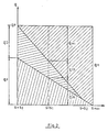
- Fig 2 shows diagrammatically the distribution of flow through the drive system according to the invention.
- Fig 3 shows a section through a flow dividing valve means comprised in the drive system in Fig 1.
- the hydraulic pump 1 delivers a flow q p to the point 2. Thereafter, the flow has three alternative ways to go, namely through the feed passage 3, the main shunt conduit 4, and the secondary shunt conduit 5. In the latter the hydraulic fluid passes the flow divider 6 and further to the tank 25. From the feed passage 3 the fluid passes through the check valves 7, 8 and 9 to the control valve sections 10, 11 and 12.
- the flow divider 6 comprises a two-way, two-position pressure responsive valve with spring return to closed position. See Fig 3.
- the activation means 16 of the valve 6 is exposed to the pressure in the main shunt conduit 4 downstream of the restriction 13, and the activation means 15 responses to the pressure in the secondary shunt conduit 5 downstream of the restriction 14.
- the latter pressure is related to the pump pressure as well as to the flow q D . Since this pressure initially is the same as the pressure in the point 2, (which is the reference point for the pressure balance on the valve 6), the valve 6 will open as the pressure on the activation means 16 plus the force of the spring 18 are not high enough to overcome the force generated by the activation means 15. Accordingly, the opening degree of the valve 6 is determined by the pressure drop across the restriction 14 which will increase until a balance is obtained in relation to the momentarily increasing flow q D .
- the drive system also comprises a pressure reducing valve 26 located between the pump 1 and the tank 25.
- the flow q D is determined indirectly by the flow q F , i.e. by the activation condition at the control valve sections 10, 11 and 12.
- the flow q F passes through the main shunt conduit 4 under a minimum of resistance.
- the total pressure drop depends on the restriction in the main shunt conduit 4 as well as on the restriction 13 which is physicically incorporated in flow divider 6.
- the relationship q F/ q D is chosen as a compromise between on one hand the level of no-load losses and on the other hand how much the flow related forces can be reduced in a relative sense within the main shunt conduit at maintained acceptable control characteristics.
- Fig 2 The distribution of the different part-flows as a function of the valve slide displacement is illustrated in Fig 2.
- the remaining displacement of the valve slide S max - S2 is then controlled by the restriction in the main shunt conduit 4 only until the entire flow goes to the activated load object.
- a flow dividing valve 6 may be designed practically.
- the right hand activation means 16 of the valve 6 is formed as a chamber which is integrated in the main shunt conduit 4 and which lodges the spring 18 for loading the valve slide 26 toward its left position, in which position the secondary shunt conduit 5 is completely blocked.
- the left activation means 15 is formed as a chamber 2 too and is incorporated in the secondary shunt conduit 5.
- the flow divider is integrated in the common inlet part of the valve sections.
Landscapes
- Engineering & Computer Science (AREA)
- Physics & Mathematics (AREA)
- Fluid Mechanics (AREA)
- Mechanical Engineering (AREA)
- General Engineering & Computer Science (AREA)
- Fluid-Pressure Circuits (AREA)
Description
- This invention relates to a hydraulic drive system comprising control valves of the type which on one hand are intended for determining the direction of flow to and from the pressure fluid consuming load objects, and which on the other hand are intended to adapt the size of the fluid flow to the objects by shunting off a surplus or no load flow to the hydraulic tank through a shunt passage. In case of a load which generates pressure fluid this shunting is obtained by a restriction control.
- The control valve type mentioned above is intended to be supplied with fluid from a pump having a constant displacement and working at a given speed level. You can see two modes of operation, namely one mode in which no fluid flow is used for effective work, and another mode in which a certain working flow is used. It is desirable to be able to control large hydraulic fluid flows (effects) by a given size of valve with moderate losses only.
- The mode of operation in which no work flow is delivered to the connected load objects means that the entire pump flow passes unrestricted through the shunt passage of the valves or through the so called free flow passage back to the tank.
- A conventional arrangement of valves comprises one or more valve sections located in parallel such that the free through passage or the shunt conduit is formed by the shunt passages of the valve sections connected in series. The restriction of the flow in the shunt conduit is obtained by cam portions on the valve slides. As the valve slides are put in their neutral positions, the area of the shunt conduit is the largest possible, but in spite of that the direction changes of the flow create considerable pressure drops which become greater the larger pump flow is forced therethrough.
- As one or more of the valve slides are displaced, a restriction of the surplus or no-load flow through the shunt conduit is obtained. A flow which corresponds to the decreasing shunt flow is forced into a parallel passage, the so called feed passage, which is connected to the respective load object.
- As long as none of the valve slides is displaced, the product of the pump flow and the pressure drop in the shunt conduit represent the no-load losses in the control valves, losses which increase in relation to the increase of the pump size. If the no-load interval is a major part of the work cycle, one realizes that it is disadvantageous to supply the valves from too big a pump or, the other way around, to choose too small valves.
- A previous attempt to solve this problem is disclosed in FR-A- 2 338 404. This known device includes one ore more control valve sections, all having a first shunt conduit. The device also comprises a flow dividing means which is located between the pump and the tank and comprises a pressure responsive shunt valve located in a second shunt conduit and a non-variable restriction located upstream of the control valve sections to establish a direct connection through the second shunt conduit from the pump to the tank in relation to the size of the fluid flow in the first shunt conduit.
- However, the flow dividing means shown in this prior device is rather complicated in structure as it requires an additional pressure limiting valve to obtain a desirable operation of the shunt valve.
- Through the invention there is accomplished a hydraulic drive system of the above related type having an improved yet simple flow dividing means for leading off directly to the tank temporary surplus flow from the pump.
- Further characteristics of the invention will appear from the following description and drawings as well as the claims.
- On the drawings:
- Fig 1 shows an operation diagram for a hydraulic drive system according to the invention including three control valve sections.
- Fig 2 shows diagrammatically the distribution of flow through the drive system according to the invention.
- Fig 3 shows a section through a flow dividing valve means comprised in the drive system in Fig 1.
- As appear from Fig 1, the
hydraulic pump 1 delivers a flow qp to thepoint 2. Thereafter, the flow has three alternative ways to go, namely through thefeed passage 3, themain shunt conduit 4, and thesecondary shunt conduit 5. In the latter the hydraulic fluid passes theflow divider 6 and further to thetank 25. From thefeed passage 3 the fluid passes through thecheck valves control valve sections - The
flow divider 6 comprises a two-way, two-position pressure responsive valve with spring return to closed position. See Fig 3. The activation means 16 of thevalve 6 is exposed to the pressure in themain shunt conduit 4 downstream of therestriction 13, and the activation means 15 responses to the pressure in the secondary shunt conduit 5 downstream of therestriction 14. The latter pressure is related to the pump pressure as well as to the flow qD. Since this pressure initially is the same as the pressure in thepoint 2, (which is the reference point for the pressure balance on the valve 6), thevalve 6 will open as the pressure on the activation means 16 plus the force of thespring 18 are not high enough to overcome the force generated by the activation means 15. Accordingly, the opening degree of thevalve 6 is determined by the pressure drop across therestriction 14 which will increase until a balance is obtained in relation to the momentarily increasing flow qD. - The relationship between the flows qF and qD is determined by the
restrictions spring 18. - The drive system also comprises a
pressure reducing valve 26 located between thepump 1 and thetank 25. - In Fig 2 there is shown a flow diagram for the cases in which one or more of the control valve sections are activated. If they are not, qM = 0, whereby the entire pump flow is divided into one part-flow qF through the
main shunt conduit 4 and a part-flow qD through theflow divider 6 and further to the tank. The flow qD is determined indirectly by the flow qF, i.e. by the activation condition at thecontrol valve sections main shunt conduit 4 as well as on therestriction 13 which is physicically incorporated inflow divider 6. - Suitably the relationship qF/qD is chosen as a compromise between on one hand the level of no-load losses and on the other hand how much the flow related forces can be reduced in a relative sense within the main shunt conduit at maintained acceptable control characteristics.
- The distribution of the different part-flows as a function of the valve slide displacement is illustrated in Fig 2. At a slide displacement S=So, the entire pump flow qp is divided into qD and qF. When S=S1, the pump flow is distributed such that qMI is directed through the
feed passage 3 to the load object and the parts qDI and qFI to thetank 25. At a slide displacement S=S2, the pressure drops across therestrictions valve 6 be dominated by thespring 18, which means than qD --> 0. The remaining displacement of the valve slide S max - S2 is then controlled by the restriction in themain shunt conduit 4 only until the entire flow goes to the activated load object. - In Fig 3 there is shown how a
flow dividing valve 6 may be designed practically. The right hand activation means 16 of thevalve 6 is formed as a chamber which is integrated in themain shunt conduit 4 and which lodges thespring 18 for loading thevalve slide 26 toward its left position, in which position thesecondary shunt conduit 5 is completely blocked. The left activation means 15 is formed as achamber 2 too and is incorporated in thesecondary shunt conduit 5. - The example on a
flow dividing valve 6 shown in Fig 3 is constructively very simple and offers an acceptable controlability. By separating theshunt conduits - Suitably the flow divider is integrated in the common inlet part of the valve sections.
- The invention does not only include the above suggested embodiments but may be freely varied within the scope of the claims.
Claims (2)
characterized By
Applications Claiming Priority (2)
| Application Number | Priority Date | Filing Date | Title |
|---|---|---|---|
| SE8701357 | 1987-04-01 | ||
| SE8701357A SE454530B (en) | 1987-04-01 | 1987-04-01 | HYDRAULIC DRIVE SYSTEM FOR ONE OR MULTIPLE HYDRAULIC ENGINES |
Publications (3)
| Publication Number | Publication Date |
|---|---|
| EP0285590A2 EP0285590A2 (en) | 1988-10-05 |
| EP0285590A3 EP0285590A3 (en) | 1989-07-12 |
| EP0285590B1 true EP0285590B1 (en) | 1992-03-04 |
Family
ID=20368061
Family Applications (1)
| Application Number | Title | Priority Date | Filing Date |
|---|---|---|---|
| EP88850115A Expired EP0285590B1 (en) | 1987-04-01 | 1988-03-31 | Hydraulic drive system |
Country Status (4)
| Country | Link |
|---|---|
| US (1) | US4845947A (en) |
| EP (1) | EP0285590B1 (en) |
| DE (1) | DE3868661D1 (en) |
| SE (1) | SE454530B (en) |
Families Citing this family (7)
| Publication number | Priority date | Publication date | Assignee | Title |
|---|---|---|---|---|
| KR940010867B1 (en) * | 1989-01-27 | 1994-11-18 | 히다찌 겐끼 가부시기가이샤 | Hydraulic driving running apparatus |
| US5203172A (en) * | 1990-05-17 | 1993-04-20 | Simpson Alvin B | Electromagnetically powered hydraulic engine |
| DE4102203A1 (en) * | 1991-01-25 | 1992-07-30 | Linde Ag | HYDRAULIC DRIVE SYSTEM |
| DE69302012T2 (en) * | 1992-12-04 | 1996-09-05 | Hitachi Construction Machinery Co., Ltd., Tokio/Tokyo | HYDRAULIC REGENERATOR |
| JP2004019873A (en) * | 2002-06-19 | 2004-01-22 | Toyota Industries Corp | Hydraulic control device and industrial vehicle equipped with the hydraulic control device |
| DE102015107857A1 (en) * | 2015-05-19 | 2016-11-24 | Linde Hydraulics Gmbh & Co. Kg | Hydrostatic drive system |
| CN111749938B (en) * | 2020-07-31 | 2025-06-10 | 徐工消防安全装备有限公司 | Hydraulic walking system and self-walking type aerial work platform |
Family Cites Families (7)
| Publication number | Priority date | Publication date | Assignee | Title |
|---|---|---|---|---|
| US3520231A (en) * | 1968-10-23 | 1970-07-14 | Gen Signal Corp | Hydraulic supply systems with flow rate-limiting control |
| US3720483A (en) * | 1971-07-23 | 1973-03-13 | Sanders Associates Inc | Hydraulic power supply system |
| DE2601484C2 (en) * | 1976-01-16 | 1984-07-26 | Robert Bosch Gmbh, 7000 Stuttgart | Control device for at least two hydraulic consumers fed by a pressure medium source |
| DE2710001A1 (en) * | 1977-03-08 | 1978-09-14 | Daimler Benz Ag | PRESSURE RELIEF VALVE FOR THE WORKING PRESSURE OF A POWER STEERING |
| DE2804045A1 (en) * | 1978-01-31 | 1979-08-09 | Bosch Gmbh Robert | CONTROL DEVICE FOR A HYDRAULICALLY OPERATED CONSUMER |
| US4441651A (en) * | 1982-10-29 | 1984-04-10 | Jefferson Industries Company | Hydraulic fan control |
| JPS61241273A (en) * | 1985-04-19 | 1986-10-27 | Tokai T R W Kk | Speed responding power steering device |
-
1987
- 1987-04-01 SE SE8701357A patent/SE454530B/en not_active IP Right Cessation
-
1988
- 1988-03-30 US US07/175,154 patent/US4845947A/en not_active Expired - Lifetime
- 1988-03-31 DE DE8888850115T patent/DE3868661D1/en not_active Expired - Lifetime
- 1988-03-31 EP EP88850115A patent/EP0285590B1/en not_active Expired
Also Published As
| Publication number | Publication date |
|---|---|
| SE454530B (en) | 1988-05-09 |
| SE8701357D0 (en) | 1987-04-01 |
| US4845947A (en) | 1989-07-11 |
| EP0285590A3 (en) | 1989-07-12 |
| DE3868661D1 (en) | 1992-04-09 |
| EP0285590A2 (en) | 1988-10-05 |
Similar Documents
| Publication | Publication Date | Title |
|---|---|---|
| US3602104A (en) | Pressure-compensated flow control | |
| US3987622A (en) | Load controlled fluid system having parallel work elements | |
| US4089167A (en) | Load responsive valve assemblies | |
| US4693272A (en) | Post pressure compensated unitary hydraulic valve | |
| US4738102A (en) | Hydrostatic drives | |
| US4082111A (en) | Load responsive fluid control valve | |
| US3744517A (en) | Load responsive fluid control valves | |
| US3592216A (en) | Flow control valve | |
| US4850191A (en) | Control arrangement for at least two hydraulic consumers fed by at least one pump | |
| US4335577A (en) | Hydraulic system having variable displacement pumps controlled by power beyond flow | |
| GB1464782A (en) | Fluid-flow valve arrangement | |
| JPS6335473B2 (en) | ||
| JPH1061603A (en) | Control system to isolate and mitigate inductive loads | |
| US6289675B1 (en) | Hydraulic control circuit for a priority and for a secondary hydraulic consumer | |
| US4253482A (en) | Hydraulic valve having pressure compensated demand flow | |
| US3973398A (en) | Hydraulic system and automatically shiftable direction control valve therefor | |
| US4028889A (en) | Load responsive fluid control system | |
| US4845947A (en) | Hydraulic drive system | |
| EP0111208A1 (en) | Power transmission | |
| EP0008523B1 (en) | Improvements relating to hydraulic control systems | |
| GB1570589A (en) | Control apparatus for at least two hydraulic loads supplied from a source of pressure medium | |
| US3561327A (en) | Flow divider and flow-dividing system | |
| US5048396A (en) | Bypass valve | |
| US4437307A (en) | Priority flow control system | |
| US4660380A (en) | Hydraulic control arrangement |
Legal Events
| Date | Code | Title | Description |
|---|---|---|---|
| PUAI | Public reference made under article 153(3) epc to a published international application that has entered the european phase |
Free format text: ORIGINAL CODE: 0009012 |
|
| AK | Designated contracting states |
Kind code of ref document: A2 Designated state(s): DE FR GB IT |
|
| PUAL | Search report despatched |
Free format text: ORIGINAL CODE: 0009013 |
|
| AK | Designated contracting states |
Kind code of ref document: A3 Designated state(s): DE FR GB IT |
|
| 17P | Request for examination filed |
Effective date: 19891223 |
|
| 17Q | First examination report despatched |
Effective date: 19901106 |
|
| GRAA | (expected) grant |
Free format text: ORIGINAL CODE: 0009210 |
|
| AK | Designated contracting states |
Kind code of ref document: B1 Designated state(s): DE FR GB IT |
|
| PG25 | Lapsed in a contracting state [announced via postgrant information from national office to epo] |
Ref country code: IT Free format text: LAPSE BECAUSE OF FAILURE TO SUBMIT A TRANSLATION OF THE DESCRIPTION OR TO PAY THE FEE WITHIN THE PRE;WARNING: LAPSES OF ITALIAN PATENTS WITH EFFECTIVE DATE BEFORE 2007 MAY HAVE OCCURRED AT ANY TIME BEFORE 2007. THE CORRECT EFFECTIVE DATE MAY BE DIFFERENT FROM THE ONE RECORDED.SCRIBED TIME-LIMIT Effective date: 19920304 |
|
| REF | Corresponds to: |
Ref document number: 3868661 Country of ref document: DE Date of ref document: 19920409 |
|
| ET | Fr: translation filed | ||
| PLBI | Opposition filed |
Free format text: ORIGINAL CODE: 0009260 |
|
| 26 | Opposition filed |
Opponent name: ROBERT BOSCH GMBH Effective date: 19921128 |
|
| PGFP | Annual fee paid to national office [announced via postgrant information from national office to epo] |
Ref country code: FR Payment date: 19930309 Year of fee payment: 6 |
|
| PGFP | Annual fee paid to national office [announced via postgrant information from national office to epo] |
Ref country code: GB Payment date: 19930319 Year of fee payment: 6 |
|
| PGFP | Annual fee paid to national office [announced via postgrant information from national office to epo] |
Ref country code: DE Payment date: 19930324 Year of fee payment: 6 |
|
| RDAG | Patent revoked |
Free format text: ORIGINAL CODE: 0009271 |
|
| STAA | Information on the status of an ep patent application or granted ep patent |
Free format text: STATUS: PATENT REVOKED |
|
| 27W | Patent revoked |
Effective date: 19940212 |
|
| GBPR | Gb: patent revoked under art. 102 of the ep convention designating the uk as contracting state |
Free format text: 940212 |