EP0284188B1 - Pressure cylinder piston - Google Patents
Pressure cylinder piston Download PDFInfo
- Publication number
- EP0284188B1 EP0284188B1 EP88301305A EP88301305A EP0284188B1 EP 0284188 B1 EP0284188 B1 EP 0284188B1 EP 88301305 A EP88301305 A EP 88301305A EP 88301305 A EP88301305 A EP 88301305A EP 0284188 B1 EP0284188 B1 EP 0284188B1
- Authority
- EP
- European Patent Office
- Prior art keywords
- components
- piston
- piston according
- sleeve
- stem
- Prior art date
- Legal status (The legal status is an assumption and is not a legal conclusion. Google has not performed a legal analysis and makes no representation as to the accuracy of the status listed.)
- Expired - Lifetime
Links
- 230000000717 retained effect Effects 0.000 claims description 7
- 230000014759 maintenance of location Effects 0.000 claims description 4
- 239000000463 material Substances 0.000 description 5
- 238000000465 moulding Methods 0.000 description 3
- 230000000740 bleeding effect Effects 0.000 description 2
- 239000012530 fluid Substances 0.000 description 2
- 229920003023 plastic Polymers 0.000 description 2
- 239000004033 plastic Substances 0.000 description 2
- 238000004026 adhesive bonding Methods 0.000 description 1
- 230000015572 biosynthetic process Effects 0.000 description 1
- 238000000034 method Methods 0.000 description 1
- 230000002093 peripheral effect Effects 0.000 description 1
- 239000007787 solid Substances 0.000 description 1
Images
Classifications
-
- F—MECHANICAL ENGINEERING; LIGHTING; HEATING; WEAPONS; BLASTING
- F16—ENGINEERING ELEMENTS AND UNITS; GENERAL MEASURES FOR PRODUCING AND MAINTAINING EFFECTIVE FUNCTIONING OF MACHINES OR INSTALLATIONS; THERMAL INSULATION IN GENERAL
- F16J—PISTONS; CYLINDERS; SEALINGS
- F16J1/00—Pistons; Trunk pistons; Plungers
- F16J1/005—Pistons; Trunk pistons; Plungers obtained by assembling several pieces
- F16J1/006—Pistons; Trunk pistons; Plungers obtained by assembling several pieces of different materials
-
- B—PERFORMING OPERATIONS; TRANSPORTING
- B60—VEHICLES IN GENERAL
- B60T—VEHICLE BRAKE CONTROL SYSTEMS OR PARTS THEREOF; BRAKE CONTROL SYSTEMS OR PARTS THEREOF, IN GENERAL; ARRANGEMENT OF BRAKING ELEMENTS ON VEHICLES IN GENERAL; PORTABLE DEVICES FOR PREVENTING UNWANTED MOVEMENT OF VEHICLES; VEHICLE MODIFICATIONS TO FACILITATE COOLING OF BRAKES
- B60T11/00—Transmitting braking action from initiating means to ultimate brake actuator without power assistance or drive or where such assistance or drive is irrelevant
- B60T11/10—Transmitting braking action from initiating means to ultimate brake actuator without power assistance or drive or where such assistance or drive is irrelevant transmitting by fluid means, e.g. hydraulic
- B60T11/16—Master control, e.g. master cylinders
-
- F—MECHANICAL ENGINEERING; LIGHTING; HEATING; WEAPONS; BLASTING
- F16—ENGINEERING ELEMENTS AND UNITS; GENERAL MEASURES FOR PRODUCING AND MAINTAINING EFFECTIVE FUNCTIONING OF MACHINES OR INSTALLATIONS; THERMAL INSULATION IN GENERAL
- F16J—PISTONS; CYLINDERS; SEALINGS
- F16J1/00—Pistons; Trunk pistons; Plungers
Definitions
- This invention relates to a piston for use in a pressure cylinder, such as a master or slave cylinder primarily intended for use in a vehicle hydraulic braking system.
- the invention also embraces a pressure cylinder incorporating such a piston.
- a pressure cylinder piston As a one-piece body and to place an annular seal on the body, usually engaged in a corresponding peripheral groove of the body.
- the assembly of the seal on to the body can require deformation of the seal over a full diameter portion of the piston prior to its engagement in the groove and this can cause undesirable stretching of the seal, or other damage, leading to a possible lack of integrity of the seal, in use.
- pistons are increasingly made as integral mouldings from plastics material and with pistons of diameter significantly greater than about one inch, for example, distortion and shrinkage of the moulded material can lead to difficulties in achieving the necessary high degree of accuracy for use in hydraulic equipment.
- An object of the present invention is to provide an improved pressure cylinder piston in which the aforesaid problems are minimised or avoided.
- Document GB-A-2051271 discloses a piston for use in a pressure cylinder comprising a pair of separately made components interfitted to form an assembly with an annular seal engaged on a surface of one of them, the seal being retained in position between the interfitted components.
- one of the components has one of more flutes extending longitudinally between the components, each flute forming a longitudinally extending passageway in the assembly.
- one of the components is a sleeve and the other is a headed stem received within the sleeve with the seal surrounding the stem component and being retained between opposed surfaces of the head and sleeve.
- the or each flute is formed in the sleeve and may conveniently communicate via passage means with a longitudinal passage in the stem.
- the provision of the flutes minimises the material required for the sleeve and the arrangement of passages ensures that any air trapped in the flutes when the piston is installed in a pressure cylinder may be expelled from the flutes and carried away during bleeding of air from the cylinder.
- Retaining means may conveniently be provided acting to retain the components in assembled relationship.
- the assembly may include a centre valve element retained in position by a retention device, the latter preferably serving also as said retaining means acting to retain said components in assembled relationship.
- the master cylinder illustrated in Figure 1 has a body 1 having a longitudinal internal bore 2 within which slides a piston 3.
- the piston is actuated, in use, by a force input rod 4 engaging the outer end of the piston by way of an enlarged head 5 which co-operates with a stop ring 6 itself retained by a circlip 7 lodged in a groove of the body, in order to limit the outward movement of the rod.
- the body has a recuperation port 8 at the forward end of the bore 2, the port being connectable to a fluid reservoir by means of a port connection 9.
- the port 8 is controlled, in conventional manner, by a centre valve assembly 10 which is connected to the piston 3 by means of a stem 11 which can be accommodated in a longitudinal bore 12 of the piston during forward movement of the latter.
- a piston return spring 13 acts, at one of its ends, against part of the valve assembly 10 and at its other end against a cap 14 mounted on a forwardly projecting end portion 15 of the piston and acting as a retention means for the rod 11.
- the piston 3 comprises two separately made components which are interfitted to form a piston assembly, as will be more clearly appreciated from Figures 2 and 3.
- One of the components is an outer sleeve 16 having a central through bore which receives a stem 17 of the other component.
- the stem 17 terminates at one end in a head 18 which, in the assembled condition of the piston, abuts against the adjacent end of the sleeve 16.
- the head 18 is formed with a relatively small diameter portion 19 providing a surface for supporting a surrounding seal 20, which is trapped between a shoulder 21, formed at the junction between the head and surface 19, and the adjacent end of the sleeve 16.
- the stem 17 projects beyond the end of the sleeve remote from the seal and has a longitudinal bore 22 extending from the free end thereof to the region of the head 18.
- This bore receives the stem 11 of the centre valve assembly 10 and the sleeve and stem are held together in their operative positions, as shown, by the retaining cap 14 for the valve stem 11.
- the cap is moved along the stem 17 into engagement with the adjacent end of the sleeve and a resilient turned-in tongue 14A of the cap snap-engages against a shoulder 17A of the stem as the cap reaches its final position to prevent withdrawal of the cap and thereby retain the sleeve and stem in assembled relationship.
- the sleeve is formed with a plurality, in this case 5, of equally angularly spaced through openings in the form of flutes 23, separated by webs 24.
- the flutes communicate via radial passages 25 with the longitudinal bore 22 of the stem 17.
- the flutes are formed during moulding of the sleeve from plastics material and serve to minimise the amount of material required for the formation of the sleeve. This is also advantageous since the relatively small bulk of the sleeve minimises the distortion occurring as a result of the moulding process and permits the sleeve to be moulded with an outer surface of the accuracy required for use as a piston.
- the piston of the invention may differ in various ways from that described above and shown in the drawings.
- the outer surface of the piston may be of uniform diameter instead of stepped, the latter configuration being used in the described embodiment for use with a valve 26 which forms no part of the invention.
- the outer surface of the piston may be grooved or stepped in a manner different to that shown.
- the stem 17 may be solid and an alternative form of retainer employed; alternatively or additionally, the piston components may be held together by press-fitting and/or bonding or glueing.
- the invention may equally be applied to a tandem or other piston arrangement.
Landscapes
- Engineering & Computer Science (AREA)
- General Engineering & Computer Science (AREA)
- Mechanical Engineering (AREA)
- Chemical & Material Sciences (AREA)
- Combustion & Propulsion (AREA)
- Transportation (AREA)
- Pistons, Piston Rings, And Cylinders (AREA)
- Transmission Of Braking Force In Braking Systems (AREA)
Description
- This invention relates to a piston for use in a pressure cylinder, such as a master or slave cylinder primarily intended for use in a vehicle hydraulic braking system. The invention also embraces a pressure cylinder incorporating such a piston.
- It is conventional practice to form a pressure cylinder piston as a one-piece body and to place an annular seal on the body, usually engaged in a corresponding peripheral groove of the body. The assembly of the seal on to the body can require deformation of the seal over a full diameter portion of the piston prior to its engagement in the groove and this can cause undesirable stretching of the seal, or other damage, leading to a possible lack of integrity of the seal, in use. Moreover, such pistons are increasingly made as integral mouldings from plastics material and with pistons of diameter significantly greater than about one inch, for example, distortion and shrinkage of the moulded material can lead to difficulties in achieving the necessary high degree of accuracy for use in hydraulic equipment.
- An object of the present invention is to provide an improved pressure cylinder piston in which the aforesaid problems are minimised or avoided.
- Document GB-A-2051271 discloses a piston for use in a pressure cylinder comprising a pair of separately made components interfitted to form an assembly with an annular seal engaged on a surface of one of them, the seal being retained in position between the interfitted components. According to the present invention one of the components has one of more flutes extending longitudinally between the components, each flute forming a longitudinally extending passageway in the assembly.
- In a typical practical arrangement, one of the components is a sleeve and the other is a headed stem received within the sleeve with the seal surrounding the stem component and being retained between opposed surfaces of the head and sleeve.
- Typically, the or each flute is formed in the sleeve and may conveniently communicate via passage means with a longitudinal passage in the stem. The provision of the flutes minimises the material required for the sleeve and the arrangement of passages ensures that any air trapped in the flutes when the piston is installed in a pressure cylinder may be expelled from the flutes and carried away during bleeding of air from the cylinder.
- Retaining means may conveniently be provided acting to retain the components in assembled relationship. In one of its possible forms, the assembly may include a centre valve element retained in position by a retention device, the latter preferably serving also as said retaining means acting to retain said components in assembled relationship.
- The invention will now be described, by way of example, with reference to the accompanying drawings in which:
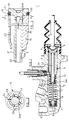
- Figure 1 is a longitudinal cross sectional view of a master cylinder embodying the piston of the invention;
- Figure 2 is an enlarged sectional view of the piston of Figure 1, and
- Figure 3 is a cross section along the line 3-3 of Figure 2.
- The master cylinder illustrated in Figure 1 has a body 1 having a longitudinal
internal bore 2 within which slides apiston 3. The piston is actuated, in use, by a force input rod 4 engaging the outer end of the piston by way of an enlargedhead 5 which co-operates with astop ring 6 itself retained by acirclip 7 lodged in a groove of the body, in order to limit the outward movement of the rod. The body has arecuperation port 8 at the forward end of thebore 2, the port being connectable to a fluid reservoir by means of aport connection 9. Theport 8 is controlled, in conventional manner, by acentre valve assembly 10 which is connected to thepiston 3 by means of astem 11 which can be accommodated in alongitudinal bore 12 of the piston during forward movement of the latter. A piston returnspring 13 acts, at one of its ends, against part of thevalve assembly 10 and at its other end against a cap 14 mounted on a forwardly projecting end portion 15 of the piston and acting as a retention means for therod 11. The remaining components illustrated form no part of the present invention and will not be further described. Moreover, operation of thevalve assembly 10 during working movement of the piston is also entirely conventional and will be familiar to a person skilled in the art. - The
piston 3 comprises two separately made components which are interfitted to form a piston assembly, as will be more clearly appreciated from Figures 2 and 3. One of the components is anouter sleeve 16 having a central through bore which receives astem 17 of the other component. Thestem 17 terminates at one end in ahead 18 which, in the assembled condition of the piston, abuts against the adjacent end of thesleeve 16. Thehead 18 is formed with a relativelysmall diameter portion 19 providing a surface for supporting a surroundingseal 20, which is trapped between ashoulder 21, formed at the junction between the head andsurface 19, and the adjacent end of thesleeve 16. - The
stem 17 projects beyond the end of the sleeve remote from the seal and has alongitudinal bore 22 extending from the free end thereof to the region of thehead 18. This bore, in use, receives thestem 11 of thecentre valve assembly 10 and the sleeve and stem are held together in their operative positions, as shown, by the retaining cap 14 for thevalve stem 11. The cap is moved along thestem 17 into engagement with the adjacent end of the sleeve and a resilient turned-intongue 14A of the cap snap-engages against ashoulder 17A of the stem as the cap reaches its final position to prevent withdrawal of the cap and thereby retain the sleeve and stem in assembled relationship. - With further reference to Figures 2 and 3, the sleeve is formed with a plurality, in this
case 5, of equally angularly spaced through openings in the form offlutes 23, separated bywebs 24. The flutes communicate viaradial passages 25 with thelongitudinal bore 22 of thestem 17. The flutes are formed during moulding of the sleeve from plastics material and serve to minimise the amount of material required for the formation of the sleeve. This is also advantageous since the relatively small bulk of the sleeve minimises the distortion occurring as a result of the moulding process and permits the sleeve to be moulded with an outer surface of the accuracy required for use as a piston. - By providing communication between the
flutes 23 and thebore 22 of thestem 17 via theholes 25, air trapped within the flutes can be expelled during normal bleeding of the master cylinder. Thewebs 24 are cut away at 24A to permit fluid to flow around the stem and into anyadjacent hole 25. - It will be understood that the piston of the invention may differ in various ways from that described above and shown in the drawings. For example, the outer surface of the piston may be of uniform diameter instead of stepped, the latter configuration being used in the described embodiment for use with a
valve 26 which forms no part of the invention. Alternatively, the outer surface of the piston may be grooved or stepped in a manner different to that shown. When it is not desired to include a centre valve element in the piston, thestem 17 may be solid and an alternative form of retainer employed; alternatively or additionally, the piston components may be held together by press-fitting and/or bonding or glueing. Although exemplified by a single piston, the invention may equally be applied to a tandem or other piston arrangement.
Claims (9)
Applications Claiming Priority (2)
| Application Number | Priority Date | Filing Date | Title |
|---|---|---|---|
| GB878704429A GB8704429D0 (en) | 1987-02-25 | 1987-02-25 | Pressure cylinder piston |
| GB8704429 | 1987-02-25 |
Publications (2)
| Publication Number | Publication Date |
|---|---|
| EP0284188A1 EP0284188A1 (en) | 1988-09-28 |
| EP0284188B1 true EP0284188B1 (en) | 1992-01-02 |
Family
ID=10612923
Family Applications (1)
| Application Number | Title | Priority Date | Filing Date |
|---|---|---|---|
| EP88301305A Expired - Lifetime EP0284188B1 (en) | 1987-02-25 | 1988-02-17 | Pressure cylinder piston |
Country Status (5)
| Country | Link |
|---|---|
| EP (1) | EP0284188B1 (en) |
| KR (1) | KR880010266A (en) |
| DE (1) | DE3867270D1 (en) |
| ES (1) | ES2028269T3 (en) |
| GB (1) | GB8704429D0 (en) |
Family Cites Families (3)
| Publication number | Priority date | Publication date | Assignee | Title |
|---|---|---|---|---|
| GB2051271B (en) * | 1979-06-12 | 1983-03-02 | Lucas Industries Ltd | Dual master cylinder braking systems |
| DE3339366A1 (en) * | 1983-10-29 | 1985-05-09 | Alfred Teves Gmbh, 6000 Frankfurt | MAIN CYLINDER |
| JPS6130725U (en) * | 1984-07-27 | 1986-02-24 | アイシン精機株式会社 | Variable valve lift type clutch master cylinder |
-
1987
- 1987-02-25 GB GB878704429A patent/GB8704429D0/en active Pending
-
1988
- 1988-02-17 ES ES198888301305T patent/ES2028269T3/en not_active Expired - Lifetime
- 1988-02-17 DE DE8888301305T patent/DE3867270D1/en not_active Expired - Lifetime
- 1988-02-17 EP EP88301305A patent/EP0284188B1/en not_active Expired - Lifetime
- 1988-02-23 KR KR1019880001862A patent/KR880010266A/en not_active Withdrawn
Also Published As
| Publication number | Publication date |
|---|---|
| KR880010266A (en) | 1988-10-07 |
| GB8704429D0 (en) | 1987-04-01 |
| DE3867270D1 (en) | 1992-02-13 |
| EP0284188A1 (en) | 1988-09-28 |
| ES2028269T3 (en) | 1992-07-01 |
Similar Documents
| Publication | Publication Date | Title |
|---|---|---|
| US6769254B2 (en) | Hydraulic operating systems for clutches and the like | |
| CA1279353C (en) | Portless type master cylinder device with non return valve and restricted passage in parallel between pressure chamber and fluid reservoir | |
| KR100313614B1 (en) | Piston with central valve for hydraulic brake system | |
| US6418717B1 (en) | Hydraulic cylinders | |
| JPS6227288B2 (en) | ||
| US4557110A (en) | Master cylinder assembly for a vehicle braking system | |
| US6381959B1 (en) | Brake master cylinder | |
| EP0284188A1 (en) | Pressure cylinder piston | |
| US4231224A (en) | Master cylinder assemblies for vehicle hydraulic braking systems | |
| US4264111A (en) | Hydraulic anti-skid device | |
| US5107680A (en) | Hydraulic cylinder | |
| EP0049969B1 (en) | A master cylinder assembly for a vehicle hydraulic braking system | |
| JPH0366185B2 (en) | ||
| JPS62157854A (en) | Connection method and device for master cylinder and vacuum brake booster device | |
| WO1988008801A1 (en) | A piston assembly | |
| EP0219833A2 (en) | Portless type master cylinder device with intake valve and flow resisting means between pressure chamber and reservoir chamber | |
| US4539892A (en) | Hydraulic brake booster | |
| US6213566B1 (en) | Brake proportioning in-line ball valve | |
| EP0383507B1 (en) | Hydraulic pressure control valve | |
| US6467268B2 (en) | Brake master cylinder | |
| US5009581A (en) | Fluid accumulator for anti-skid brakes | |
| EP0277465A1 (en) | Servo-distributor for a pneumatic braking system of a tractor, for controlling the braking of a trailer towed by the tractor | |
| US6817179B1 (en) | Poppet for center port compensation valve | |
| US5018796A (en) | Hydraulic pressure control valve | |
| US4860541A (en) | Two stage relief valve for master cylinder quick-fill chamber |
Legal Events
| Date | Code | Title | Description |
|---|---|---|---|
| PUAI | Public reference made under article 153(3) epc to a published international application that has entered the european phase |
Free format text: ORIGINAL CODE: 0009012 |
|
| AK | Designated contracting states |
Kind code of ref document: A1 Designated state(s): DE ES FR GB IT |
|
| 17P | Request for examination filed |
Effective date: 19890309 |
|
| 17Q | First examination report despatched |
Effective date: 19900713 |
|
| GRAA | (expected) grant |
Free format text: ORIGINAL CODE: 0009210 |
|
| AK | Designated contracting states |
Kind code of ref document: B1 Designated state(s): DE ES FR GB IT |
|
| ITF | It: translation for a ep patent filed | ||
| REF | Corresponds to: |
Ref document number: 3867270 Country of ref document: DE Date of ref document: 19920213 |
|
| ET | Fr: translation filed | ||
| REG | Reference to a national code |
Ref country code: ES Ref legal event code: FG2A Ref document number: 2028269 Country of ref document: ES Kind code of ref document: T3 |
|
| PLBE | No opposition filed within time limit |
Free format text: ORIGINAL CODE: 0009261 |
|
| STAA | Information on the status of an ep patent application or granted ep patent |
Free format text: STATUS: NO OPPOSITION FILED WITHIN TIME LIMIT |
|
| 26N | No opposition filed | ||
| PGFP | Annual fee paid to national office [announced via postgrant information from national office to epo] |
Ref country code: GB Payment date: 19950207 Year of fee payment: 8 |
|
| PGFP | Annual fee paid to national office [announced via postgrant information from national office to epo] |
Ref country code: FR Payment date: 19950210 Year of fee payment: 8 |
|
| PG25 | Lapsed in a contracting state [announced via postgrant information from national office to epo] |
Ref country code: GB Effective date: 19960217 |
|
| GBPC | Gb: european patent ceased through non-payment of renewal fee |
Effective date: 19960217 |
|
| PG25 | Lapsed in a contracting state [announced via postgrant information from national office to epo] |
Ref country code: FR Effective date: 19961031 |
|
| REG | Reference to a national code |
Ref country code: FR Ref legal event code: ST |
|
| REG | Reference to a national code |
Ref country code: ES Ref legal event code: PC2A |
|
| PG25 | Lapsed in a contracting state [announced via postgrant information from national office to epo] |
Ref country code: IT Free format text: LAPSE BECAUSE OF NON-PAYMENT OF DUE FEES;WARNING: LAPSES OF ITALIAN PATENTS WITH EFFECTIVE DATE BEFORE 2007 MAY HAVE OCCURRED AT ANY TIME BEFORE 2007. THE CORRECT EFFECTIVE DATE MAY BE DIFFERENT FROM THE ONE RECORDED. Effective date: 20050217 |
|
| PGFP | Annual fee paid to national office [announced via postgrant information from national office to epo] |
Ref country code: ES Payment date: 20050309 Year of fee payment: 18 |
|
| PGFP | Annual fee paid to national office [announced via postgrant information from national office to epo] |
Ref country code: DE Payment date: 20050331 Year of fee payment: 18 |
|
| PG25 | Lapsed in a contracting state [announced via postgrant information from national office to epo] |
Ref country code: ES Free format text: LAPSE BECAUSE OF NON-PAYMENT OF DUE FEES Effective date: 20060218 |
|
| REG | Reference to a national code |
Ref country code: ES Ref legal event code: PC2A |
|
| PG25 | Lapsed in a contracting state [announced via postgrant information from national office to epo] |
Ref country code: DE Free format text: LAPSE BECAUSE OF NON-PAYMENT OF DUE FEES Effective date: 20060901 |
|
| REG | Reference to a national code |
Ref country code: ES Ref legal event code: FD2A Effective date: 20060218 |