EP0284075B1 - Radar system consisting of an array of interconnected elementary satellites - Google Patents
Radar system consisting of an array of interconnected elementary satellites Download PDFInfo
- Publication number
- EP0284075B1 EP0284075B1 EP88104767A EP88104767A EP0284075B1 EP 0284075 B1 EP0284075 B1 EP 0284075B1 EP 88104767 A EP88104767 A EP 88104767A EP 88104767 A EP88104767 A EP 88104767A EP 0284075 B1 EP0284075 B1 EP 0284075B1
- Authority
- EP
- European Patent Office
- Prior art keywords
- radar
- elementary
- satellites
- radar system
- satellite
- Prior art date
- Legal status (The legal status is an assumption and is not a legal conclusion. Google has not performed a legal analysis and makes no representation as to the accuracy of the status listed.)
- Expired - Lifetime
Links
- 238000005259 measurement Methods 0.000 claims description 14
- 230000005540 biological transmission Effects 0.000 claims description 11
- 230000003287 optical effect Effects 0.000 claims description 10
- 238000012545 processing Methods 0.000 claims description 6
- 230000005855 radiation Effects 0.000 claims description 5
- 238000002592 echocardiography Methods 0.000 claims description 3
- 238000002310 reflectometry Methods 0.000 claims description 3
- 230000003044 adaptive effect Effects 0.000 description 5
- 238000000034 method Methods 0.000 description 5
- 238000012937 correction Methods 0.000 description 4
- 238000001914 filtration Methods 0.000 description 4
- 230000006870 function Effects 0.000 description 4
- 238000004891 communication Methods 0.000 description 3
- 238000005516 engineering process Methods 0.000 description 3
- 230000001427 coherent effect Effects 0.000 description 2
- 230000010355 oscillation Effects 0.000 description 2
- 230000001629 suppression Effects 0.000 description 2
- 238000003491 array Methods 0.000 description 1
- 230000015556 catabolic process Effects 0.000 description 1
- 238000007796 conventional method Methods 0.000 description 1
- 238000013016 damping Methods 0.000 description 1
- 238000006731 degradation reaction Methods 0.000 description 1
- 238000009795 derivation Methods 0.000 description 1
- 238000010586 diagram Methods 0.000 description 1
- 230000000694 effects Effects 0.000 description 1
- 239000000284 extract Substances 0.000 description 1
- 230000007257 malfunction Effects 0.000 description 1
- 239000000463 material Substances 0.000 description 1
- 238000007493 shaping process Methods 0.000 description 1
- 230000008054 signal transmission Effects 0.000 description 1
- 238000012546 transfer Methods 0.000 description 1
Images


Classifications
-
- G—PHYSICS
- G01—MEASURING; TESTING
- G01S—RADIO DIRECTION-FINDING; RADIO NAVIGATION; DETERMINING DISTANCE OR VELOCITY BY USE OF RADIO WAVES; LOCATING OR PRESENCE-DETECTING BY USE OF THE REFLECTION OR RERADIATION OF RADIO WAVES; ANALOGOUS ARRANGEMENTS USING OTHER WAVES
- G01S7/00—Details of systems according to groups G01S13/00, G01S15/00, G01S17/00
- G01S7/003—Transmission of data between radar, sonar or lidar systems and remote stations
- G01S7/006—Transmission of data between radar, sonar or lidar systems and remote stations using shared front-end circuitry, e.g. antennas
-
- B—PERFORMING OPERATIONS; TRANSPORTING
- B64—AIRCRAFT; AVIATION; COSMONAUTICS
- B64G—COSMONAUTICS; VEHICLES OR EQUIPMENT THEREFOR
- B64G1/00—Cosmonautic vehicles
- B64G1/10—Artificial satellites; Systems of such satellites; Interplanetary vehicles
- B64G1/1021—Earth observation satellites
-
- B—PERFORMING OPERATIONS; TRANSPORTING
- B64—AIRCRAFT; AVIATION; COSMONAUTICS
- B64G—COSMONAUTICS; VEHICLES OR EQUIPMENT THEREFOR
- B64G1/00—Cosmonautic vehicles
- B64G1/10—Artificial satellites; Systems of such satellites; Interplanetary vehicles
- B64G1/1021—Earth observation satellites
- B64G1/1035—Earth observation satellites using radar for mapping, surveying or detection, e.g. of intelligence
-
- B—PERFORMING OPERATIONS; TRANSPORTING
- B64—AIRCRAFT; AVIATION; COSMONAUTICS
- B64G—COSMONAUTICS; VEHICLES OR EQUIPMENT THEREFOR
- B64G1/00—Cosmonautic vehicles
- B64G1/10—Artificial satellites; Systems of such satellites; Interplanetary vehicles
- B64G1/1085—Swarms and constellations
-
- B—PERFORMING OPERATIONS; TRANSPORTING
- B64—AIRCRAFT; AVIATION; COSMONAUTICS
- B64G—COSMONAUTICS; VEHICLES OR EQUIPMENT THEREFOR
- B64G3/00—Observing or tracking cosmonautic vehicles
-
- G—PHYSICS
- G01—MEASURING; TESTING
- G01S—RADIO DIRECTION-FINDING; RADIO NAVIGATION; DETERMINING DISTANCE OR VELOCITY BY USE OF RADIO WAVES; LOCATING OR PRESENCE-DETECTING BY USE OF THE REFLECTION OR RERADIATION OF RADIO WAVES; ANALOGOUS ARRANGEMENTS USING OTHER WAVES
- G01S13/00—Systems using the reflection or reradiation of radio waves, e.g. radar systems; Analogous systems using reflection or reradiation of waves whose nature or wavelength is irrelevant or unspecified
- G01S13/02—Systems using reflection of radio waves, e.g. primary radar systems; Analogous systems
- G01S13/06—Systems determining position data of a target
- G01S13/42—Simultaneous measurement of distance and other co-ordinates
Definitions
- a further implementation of this invention processes the radar signal and extracts information within the ground station; this does not modify the peculiar characteristics and operation of the invention if not for a greater capacity of the transmitting link toward ground, however compatible with the present state of the art.
- This invention may be used for primary, secondary and both radar surveillance; furthermore it may be used for the selective type of secondary radar, known as SSR Mode S, which, further to the surveillance function, carries out that of data transmission toward and from surveilled aircraft, as well known to experts and users of radar surveillance and of air traffic control systems.
- SSR Mode S selective type of secondary radar
- Such data are sent to processor (22) which also receives precise information on elementary satellite position from processor (23). On the basis of such information, processor (22) calculates the coefficients required for beamforming, converted into suitable commands by generator (25), coded by coder (27) and sent to such elementary satellites by transmitter (28).
- the waveform is decoded (36), suitably amplified by the so called transmitter driver (37) and sent to the transmitter section of the antenna (32).
- the radar echo (and/or SSR reply) coming from the target is received by antenna (32) of each elementary satellite, where the radiation pattern is formed by network (31); the resulting radar signal is coded by coder (27) and transmitted to the main satellite by transmitter (28), which, in the preferred implementation, is of the optical type.
- a telemetry subsystem which, in its preferred form of implementation, is of the laser type, where a laser telemeter (21) fitted on the main satellite is pointed onto suitable laser retroreflectors (33) fitted to each elementary and pulling satellite; pointing is aided by an angle measurement device (16) which uses the output of receivers (17) to measure the angle of arrival of the signal transmitted by the satellite and therefore also its angle position.
Landscapes
- Engineering & Computer Science (AREA)
- Remote Sensing (AREA)
- Physics & Mathematics (AREA)
- General Physics & Mathematics (AREA)
- Radar, Positioning & Navigation (AREA)
- Astronomy & Astrophysics (AREA)
- Aviation & Aerospace Engineering (AREA)
- Computer Networks & Wireless Communication (AREA)
- Evolutionary Computation (AREA)
- Radar Systems Or Details Thereof (AREA)
- Control Of Position, Course, Altitude, Or Attitude Of Moving Bodies (AREA)
- Variable-Direction Aerials And Aerial Arrays (AREA)
Description
- The present invention relates to a radar system for primary surveillance of an airspace as set forth in the preamble of
claim 1. - Such a distributed array radar system (DAR) is known by IEEE Transactions on Aerospace and Electronic systems, vol. AES-19, no. 6, Nov. 1983, pp 831-839 (4). The general concept of this radar is described which has a certain number of transmitting and of receiving units. The basic radar equation is interpreted, i.e. the signal/noise ratio of the DAR, but there is no hint as how to guarantee the coherence of the DAR.
- In "Proceedings of IGARSS Symposium", Zürich, 8-11 Sept. 1986, pp 697 - 701, Kaplan decribes the application of a spaceborne distributed aperture/coherent array processing (SDA/CAP) technology to active and passive microwave remote sensing. Nothing is to be found how to guarantee the geometry of the system.
- This invention belongs to the field of primary and secondary surveillance radars which are meant to detect mobile targets (such as aircraft), measures their present position, predict their future position and finally, as far as possible, identify them. It is a well known fact that radar surveillance is applied to the civil (e.g. as an Air Traffic Aid) and military field (e.g. defence of the airspace).
- The coverage of a ground based surveillance system is limited by the horizon and by orographic constraints, particularly at relatively low altitude; a spaceborn system, by utilising artificial satellites, is not affected by such limitations and can cover a very large area and distribute surveillance data to many users.
- The main functional and operating characteristics of airspace radar surveillance, to date at an early definition stage, are highlighted in a few recent publications, such as:
- (1) W. J. Caime "Space-based radar application to Air Traffic Control", IEEE Internal. Radar Conference, Arlington, May 6-9, 1985 (IEEE Cat No 85 CH 2076-8), pp 312-321.
- [2] E. Brookner: "Derivation of a satellite radar architecture for air surveillance", IEEE Eascon - 1983 (IEEE Cat. No. 0531-6863/83), pp 465-475.
- [3] G. Galati, G. Losquadro "Space-based multifunction radar systems: future tool for civilian and military surveillance 42nd Symposium of the Guidance & Control Panel of the AGARD, Bruxelles, 10-13 June 1986, pp 31.1-31.9.
- As highlighted in article |3| above, radar surveillance systems may use the primary, the secondary, or both, radars.
- The characteristics and operation of the primary & secondary radar, which are standard systems used by the International Civil Aviation, are well known to the relevant experts and operators.
- Space borne surveillance cannot be performed by simply carrying present techniques and technologies of primary and secondary radars on board artificial satellites because of two types of problems, both due to the very large distance (in the order of thousands of kilometers) between the radar antenna and the targets to be detected.
- The first problem is that of the power required to be transmitted, particularly high for the primary radar, because the product of the square of the antenna effective area and power transmitted is proportional to the fourth power of range.
- Therefore the need arises for a high power transmitter and for an antenna with a very large effective area, or in other terms, having high gain.
- The second problem is that of the very high angle accuracy required to achieve accurate location at long range, comparable to that achievable with groundbased systems operating at much shorter ranges. This last requirement too needs an antenna with a very narrow main lobe, and therefore very high gain. The dimensions of antennae with such performance are particularly large (from a few hundred to a few thousand times) compared to the radar operating wavelenght. This is set by operating and mission requirements for the primary radar, typically between 10 and 25 cm, and by International Civil Aviation rules for secondary radars, known as SSRs, set at 27.5 cm and 29.1 cm. Previous techniques attempted to solve, at least partly, these problems by means of physically large antennae, unfoldable in space in differing configurations. Mechanical and electrical aspects make the use of such antennae very critical and pose a limit to the maximum dimensions obtainable, fixed at few tens of meters per side, which does not provide complete satisfaction of the requirement.
- This invention overcomes such limitations by means of a radically innovative concept; the invention is based upon a given number of modules orbiting around the Earth, called elementary satellites, each operating as an element of a phased array having very large dimensions. Each elementary satellite is provided with an antenna, a transponder and a communications subsystem interfacing the main satellite. The latter, which may be duplicated to increase the availability of the entire system, provides for coherent combination of the radar signals coming from the various elementary satellites, and this way an antenna with a radiating pattern having a very narrow main beam is obtained, comparable with that of a physical antenna with the same area occupied by the elementary satellites. This way a distributed array antenna is obtained, suitable for primary and secondary radars. The application, at least at the conceptual level, of the distributed array concept to the primary radar, with reference to the multistatic case, where transmitters and receivers are located at different points, is described in a recently published work:
- [4] R.C. Hermiller, J.E. Belyea, P.G. Tomlinson: "Distributed Array Radar", IEEE Transactions on Aerospace & Electronic Systems Vol. AES-19 No. 6 November 1983, pp 831-839.
- For application to Air Space Surveillance, monostatic operation is preferred (see [2] as an example) and a much larger than unity ratio (of the order of 100 : 1) between array area (i.e. the area over which the elementary satellites are distributed) and the sum of the areas of the array elements is required; under such conditions the concept of distributed array as shown in [4] is not conveniently applied, as it would give way to an excessive degradation of the undesired lobes of the resulting radiating pattern. Such lobes are mainly a consequence of the thinned array, i.e. because the ratio of the areas above is much greater than unity.
- This invention eliminates such obstacle by relying upon the concept, well known to experts in array antennae and in systems using them, that the radiating pattern of an array is the product of an element factor (radiating pattern of the single element of the array) with an array factor (which is a function of the number and location of elements in the array alone). With previous state of the art, the array elements were very simple (such as dipoles) and their radiating pattern, almost constant within a wide angle, was not predictable. On the contrary, the elements used in this invention are complex antennae, which may also preferably be made by phased arrays, or at least having predictable radiating patterns. Such elementary antennae can direct the beam (the main lobe of their radiating pattern) in an assigned direction and: a) can generate adaptively very low gain values (so called nulls of the radiating pattern) in a number of assigned directions, about equal to the number of elementary radiators making up the antenna, preferably outside the main beam; or (6) may have very low gain values in all directions outside the main lobe.
- To attenuate, or as commonly said, to suppress the undesired lobes within the main lobe of the elementary satellite antenna (and therefore of the element of the distributed array) this invention makes use of the concept of adaptive generation also at the distributed array level.
- The adaptive generation of nulls concept and, more generally, adaptive shaping of an antenna radiating pattern, is described in many papers, among which the following:
- [5] J.W.R. Griffths "Adaptive Array Processing A Tutorial" IEEE Procedings Vol. 130, Pts F and H,
No 1, February 1985 pp. 3-10. - In this invention, the decision on which undesired lobes to suppress is taken by the main satellite processor on the basis of the following data:
- a) Ratio between the level of each lobe and the level of the main lobe of the radiating diagram of the distributed array.
- b) Reflectivity of the position of Earth surface regarded by each lobe (clutter map).
- c) Geometry (range and dimension) of the radar resolution cells which regard the surface areas above.
- Such information is contained in the main satellite control computer; that of item a) is measured periodically on the ground through measurement of one way radiating pattern, while items b) and c) are updated on board by a calibration device, consisting of two sections: a passive section utilising transmitters at known locations on the surface of the Earth and in the frequency bands in which the space borne radar system operates, providing accurate geometric calibration, and an active section, which measures the level of the radio echo (clutter signal) coming from various positions of the surface of the Earth.
- A further datum which the central computer of the main satellite needs to generate the radiation pattern of the distributed array, is the geometry of the array itself. Such geometry is controlled, within tight tolerance, by a non rigid structure, preferably implemented by wire, which prevents the elementary satellites from dispersing due to effects of various origin (differences in orbit velocity and gravitational field, solar wind etc.). Suitable dampers limit structure oscillations. The elementary satellites are mechanically connected to such structure, which takes the shape of a flat network which is kept under tension through suitable satellites, called "pulling satellites", equal in number to the vertexes of the polygon encompassing the network. The main satellite is preferably sited on the axis perpendicular to the network plane and mechanically attached to it (preferably by wire); it may also operate as a self pulling satellite. The satellite pulling forces and their resulting momentum are null, or such as to make the required corrections to the orbit and/or system attitude.
- Such control is centralised on the main satellite, where the entire system geometry is known at all times. Accurate satellite position measurement, by the main satellite, is obtained preferably by means of laser telemeter as described in the following.
- Each elementary or pulling satellite has three laser retroreflectors, i.e. plates of a material which has a much higher reflecting capacity than the rest of the satellite surface. A laser telemeter, built according to the criteria well known to the experts and fitted to the main satellite, is aimed onto the retroreflectors so as to provide three extremely accurate range measurements, from which the on board computer can obtain position and attitude of each elementary satellite. Aiming of the laser telemeter is facilitated by using the angle of the elementary or pulling satellite and the main satellite, the latter obtained through the measurement of the angles of arrival of the communications subsystem carrier between satellites (inter-satellite link). In one of the preferred implementations of this invention, such subsystem is optical; the theory and applications of optical techniques and technologies for data transmission are illustrated in many works, among which the well known:
- [6] R.M. Gagliardi, S. Karp: Optical Communications, J. Wiley & Sons, 1975.
- However their use for radar signal transmission in space does not appear to be described in literature. The advantages of optical transmission, preferably by means of laser are:
- very high directivity
- extremely wide band (channel capacity)
- reduced weight and dimensions.
- Within this invention, the inter-satellite link provides exchange of the following data (as a non limiting example):
- From main satellite to elementary satellite:
- a1) Waveform to be transmitter;
- a2) Commands for active beam forming;
- a3) Auxiliary signals and data (for synchronization, control & satellite functional check).
- From elementary satellite to main satellite:
- b1) Radar echo (and/or SSR reply)
- b2) Status and diagnostics data
- From main satellite to pulling satellite: data for orbit and attitude control.
- From pulling satellite to main satellite: status and diagnostic data.
- A further implementation of this invention makes use of a conventional radio link, at the same radar frequencies or at shifted or submultiple frequencies, to transmit the waveform which (following multiplication or frequency shift) is amplified and phase shifted in the elementary satellites; the radio link may also be used in this configuration, for the data at a2) and a3). The secondary satellite radio receiver antenna has a sufficiently high directivity and front to back ratio to avoid that the radio transmission is affected by the radar signal transmitted when a sub multiple of the radar frequency is not used. This way, the combination of radar signals coming from elementary satellites is suitably implemented in radio frequency terms at antenna level.
- Finally, the main satellite is equipped with a data link operating toward one or more ground stations for the exchange of data required for control and calibration and for transmission toward ground of the radar data, processed to the most suitable degree.
- Such link may be implemented using the most conventional techniques. In the best preferred form, radar data is processed on board, so that the "track messages" are transmitted toward ground, including therefore position, speed and possible auxiliary information related to the targets observed.
- A further implementation of this invention processes the radar signal and extracts information within the ground station; this does not modify the peculiar characteristics and operation of the invention if not for a greater capacity of the transmitting link toward ground, however compatible with the present state of the art.
- This invention may be used for primary, secondary and both radar surveillance; furthermore it may be used for the selective type of secondary radar, known as SSR Mode S, which, further to the surveillance function, carries out that of data transmission toward and from surveilled aircraft, as well known to experts and users of radar surveillance and of air traffic control systems.
- This invention, in one of its forms of implementation, makes use of the well known monopulse technique to improve angle measurement accuracy, especially under the condition of very low number of radar echoes or SSR replies coming from each target.
- This situation is particularly true for the above mentioned SSR Mode S.
- This invention will now be described with reference to one of its presently preferred forms of implementation, which is reported as a non limiting example and with reference to the figures and drawings attached, where:
- Figure 1 shows the Spaceborne Surveillance Radar in its preferred general functional configuration:
- 1. Main satellite
- 2. Distributed array
- 3. Elementary satellite
- 4. Pulling satellite
- 5. Ground Station
- 6. Segment of the connecting structure
- 7. Damping element of the connecting structure.
- Figure 2 shows the same system in its preferred general configuration and in simplified perspective view.
- Figure 3 shows the main satellite in its preferred general configuration:
- 8. Receiver & Transmitter for the exchange of data with the ground station.
- 9. Radar data extractor
- 10. Processing of radar signal
- 11. Decoder
- 12. Primary power source and power supplies
- 13. Central Computer
- 14. Central Computer memory and stored maps
- 15. Stabile Oscillator
- 16. Measurement device of the angle coordinates of the elementary satellites and pulling satellites.
- 17. Receiver of the inter satellite subsystem in the preferred optical configuration.
- 18. Ion motors and other actuators for orbit and attitude control.
- 19. Orbit and Attitude Control Unit
- 20. Laser aiming device used for telemetry
- 21. Laser telemeter
- 22. Processor for antenna beamforming
- 23. Processor for position and attitude of elementary and pulling satellites.
- 24. Processor for orbit and attitude control of the whole system.
- 25. Generator of system radiation pattern commands.
- 26. Generator of controls and synchronization of elementary satellites (radar part).
- 27. Coder of information to be transmitted
- 28. Transmitter subsystem between satellites; in the preferred implementation, of the optical type.
- 29. Processor for radar system management.
- 30. Radar waveform generator.
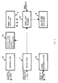
- Figure 4 shows an elementary satellite in its preferred general configuration:
- 31. Antenna pattern forming network
- 32. Antenna, in the preferred phase array configuration including receiver and transmitter.
- 33. Laser retroreflector
- 34. Processor for status and diagnostic management for the various parts of the satellite.
- 35. Antenna pattern control unit
- 36. Received signal decoder
- 37. Radar transmission driver.
- Figure 5 finally shows a pulling satellite in its preferred general configuration. Such satellite includes functional blocks identical to those present in the other satellites shown above, and in addition block (38) which is an orbit and attitude control which is managed by the main satellite.
- This invention will now be described according to its general operating principle.
- Depending upon the operating mode selected by the central computer (13) of the main satellite (1) (Figure 3), the management processor (29) of the radar system sends suitable commands to the controls and synchronisms generator (26) and to the transmitted waveform generator (30); controls, synchronisms and waveforms are coded and transmitted to all elementaray satellites, simultaneously. In parallel, as a function of surveillance requirements and of the related environment, the central computer (13) sets the aiming direction of the beam; furthermore as a function of data a), b) and c) described in the first part of this application, contained in memory (14), the central computer (13) establishes the strategy for the suppression of sidelobes.
- Such data (pointing direction and suppression strategy) are sent to processor (22) which also receives precise information on elementary satellite position from processor (23). On the basis of such information, processor (22) calculates the coefficients required for beamforming, converted into suitable commands by generator (25), coded by coder (27) and sent to such elementary satellites by transmitter (28).
- Receiver (17) of each elementary satellite (Figure 4) sends such commands, decoded by decoder (36), to another control unit (35) which completes processing and actuates commands acting upon the beamforming network (31) adapting the phased array in transmission and in reception.
- During transmission, the waveform is decoded (36), suitably amplified by the so called transmitter driver (37) and sent to the transmitter section of the antenna (32).
- Later on, the radar echo (and/or SSR reply) coming from the target is received by antenna (32) of each elementary satellite, where the radiation pattern is formed by network (31); the resulting radar signal is coded by coder (27) and transmitted to the main satellite by transmitter (28), which, in the preferred implementation, is of the optical type.
- Such signal is received by receiver (17) (which is also of the optical type in the preferred form of implementation) (Figure 3) and sent to decoder (11) which uses the reference oscillation of the same stable oscillator (15) used for transmission coding in coder (27). The decoded radar signal is then transferred to processor (10) where noise filtering takes place (so called matched filtering or close approximation thereof), or that of different types of interference, firstly that of so called clutter undesired returns.
- In the preferred form of implementation of this invention, within signal processing block (10) also the combination of signals coming from various elementary satellites takes place (spatial filtering, which synthesizes the distributed array).
- Such combination, in another form of implementation, takes place at radiofrequency level at the antenna which forms part of the electronic receiver, (17) in Figure 3.
- The data of interest to operation, relevant to targets, is obtained from the extractor (9) by means of further filtering of the radar information coming from processor (10) and later transferred to the ground station by means of subsystem (8).
- Through the same subsystem (8) the information needed for beamforming and radar system management reaches the main computer (13); the latter, which includes type of waveform, controls and synchronisms, is processed by the management processor (29) which drives the controls and synchronisms generator (26) and waveform generator (30), the outputs of which are coded and transmitted to the elementary satellites by blocks (27) and (28).
- Accurate knowledge of the distributed array geometry is obtained by means of a telemetry subsystem, which, in its preferred form of implementation, is of the laser type, where a laser telemeter (21) fitted on the main satellite is pointed onto suitable laser retroreflectors (33) fitted to each elementary and pulling satellite; pointing is aided by an angle measurement device (16) which uses the output of receivers (17) to measure the angle of arrival of the signal transmitted by the satellite and therefore also its angle position. The range measurements made by the laser telemeter (21) together with the angles provided by unit (16) are processed by computer (23) which determines the attitude of system satellites; such data is further processed to obtain the orbit and attitude corrections which are coded (27) and transmitted (28) to the pulling satellites, where they are received by receiver (17) and used by the orbit and attitude control system managed by the main satellite, block (38) which actuates them. The same position and attitude data is sent to the beam forming processor (22) where, as seen above, they are used to calculate the coefficients required for adaptive beamforming.
- The distributed beamforming is calibrated exploiting the radar echoes of particular points on the Earth surface (known high reflectivity points) and using the replies sent by suitable SSR transponders set at well known positions. The difference between known position (stored in main computer (13)) and that measured by the radar system and transferred by extractor (9) to computer (13), is utilized by the same computer (13) to generate the correction commands, which are sent to the antenna beamforming processor (22). The difference between echo and reply amplitude and the related expected value may also be used, in a very similar manner, to check possible defocussing of the phased array and to perform the required corrections.
- The main satellite has its own orbit and attitude control (19) with related actuators (18) as well as the orbit and attitude control processor of the entire system (24) which, by means of coder (27) and transmitter (28) sends control signals to each pulling satellite, where such signals are received by receiver (7) (Figure 5), which is optical, in the preferred implementation, and sent to the orbit and attitude control subsystem (38).
- All satellites are equipped with their own electrical power supply subsystem, which includes a primary power source (12) (preferably implemented by means of solar panels and batteries) and supplies for all on board users.
- Finally, the elementary and pulling satellites can transfer to the main satellite the information related to status and possible malfunctions (diagnostics), which are before hand processed and coded by a suitable processor (34).
Claims (20)
- Radar system for primary surveillance of an airspace, comprising a plurality of elementary satellites each operating as an element of a distributed array and a ground station, characterised in that the radar system is adapted to also provide secondary surveillance of said airspace and in that the elementary satellites (3) are interconnected by a non-rigid structure (2) having dampers (7) and segments (6) kept under tension and in balance by pulling satellites (4) being equipped with attitude and orbit controls managed by a main satellite (1) which is adapted to receive radar signals for processing from the elementary satellites (3) and to transmit the processed data to the ground station (5).
- Radar system according to claim 1, wherein the main satellite (1) is a pulling satellite.
- Radar system according to claim 1 or 2, wherein radar signals coming from the elementary satellites (3) are combined coherently and adaptively, so as to synthesize a phased array, and wherein the coefficients of such combination are calculated by a processor in order to attenuate the sidelobes and maximize the signal to noise ratio.
- Radar system according to claim 3, wherein the processor comprises a central computer (13), an antenna-beam forming processor (22) and a beam forming command generator (25).
- Radar system according to any one of the preceding claims, wherein each elementary satellite (3) has an antenna (32) which is preferably a phased array, with coefficients determined on the basis of commands coming from the main satellite (1) with the purpose of attenuating sidelobes and maximizing signal to noise ratio.
- Radar system according to claim 4 or 5, wherein an accurate measurement device of position and attitude of the elementary satellites (3) is arranged on the main satellite (1) and has the task of calculating said coefficients by means of an antenna beam forming processor (22) and transmitting them, following coding (27), by means of a transmitter (28), preferably of the optical type, to the elementary satellites (3).
- Radar system according to any one of the preceding claims wherein a subsystem for the accurate measurement of the position of the pulling satellites (4) is fitted on board the main satellite (4) with the purpose of providing it with orbit and attitude control of the entire system by means of a suitable processor (24) and with transmission of commands and controls generated by the processor (24), by means of a coder (27) and a transmitter (28), towards the orbit and attitude control subsystem (38) of the pulling satellites (4) to drive suitable actuators (18) which include, preferably, ion motors.
- Radar system according to claim 7, wherein the position measurement subsystem comprises a laser telemeter (21), an angle measurement unit (16) which helps to point the laser telemeter and a position computer (23) and also laser retroreflectors (33), preferably three in number, on each elementary (3) and pulling satellite (4).
- Radar system according to any one of the preceding claims, wherein the exchange of signals and data between the main satellite (1) and the pulling and elementary satellites is performed optically by means of suitable transmitters (28), receivers (17), coders (27) and decoders (36).
- Radar system according to any one of the preceding claims, wherein the exchange of signals and data between the main satellite (1) and the elementary and pulling ones is carried out by radio, and wherein the radar signals coming from targets are transmitted by the elementary satellites (3) to the main satellite (1), therafter combined by the receiver antenna (17) of the main satellite (1).
- Radar system according to claim 10, wherein the transmission of radar signals from the elementary satellites (3) to the main satellite (1) is implemented at the same frequency at which the radar signals are received by the elementary satellites, or at a multiple or submultiple or at a shifted value of such frequency.
- Radar system according to claim 10, characterised by the use of shift or multiplication/division of frequency within the receiver (17) and transmitter (28) of the elementary satellite (3).
- Radar system according to any one of the preceding claims, wherein the central computer (13) of the main satellite (1) stores in its memory (14) the following data:- ratio between sidelobes and peak of the distributed array,- reflectivity of the surface of the earth covered by the array radiation pattern,- geometry of the radar resolution cells of interest: such data is periodically updated by the main computer on the basis of measurements from the ground through receiver (8) and utilized to calculate beam forming coefficients.
- Radar system according to any one of the preceding claims, wherein the combination of radar signals coming from the elementary satellites (3) is performed by suitable coefficients which synthesize the monopulse radiation patterns to improve the accuracy of the angle measurement.
- Radar system according to any one of the preceding claims, wherein the radar signal processor (10) and data extractor (9) are housed in the ground station (5) rather than in the main satellite (1).
- Radar system according to any one of the preceding claims, wherein the radar echoes of particular portions of the surface of the Earth and the SSR replies of particular transponders set at known sites are used to achieve continuous calibration through which the beam pointing errors and possible defocussing are corrected.
- Radar system according to any one of the preceding claims, adapted to be used for primary/secondary radar surveillance and for defence or civil applications, including the selective secondary radar and its numeric data link.
- Radar system according to any one of the preceding claims, adapted to operate from low or high or geostationary orbits.
- Primary and/or secondary airspace surveillance radar, made up of a group of systems as described in any one of the preceding claims, each located in a suitable orbit so as to assure continuous surveillance of an area of interest or global coverage.
- Radar system for airspace surveillance from space, comprising a group of systems according to claim 18, whereby the group is managed by a group main satellite, operating in the same manner as the system main satellite according to any one of the preceding claims.
Applications Claiming Priority (2)
| Application Number | Priority Date | Filing Date | Title |
|---|---|---|---|
| IT4777287 | 1987-03-26 | ||
| IT47772/87A IT1205769B (en) | 1987-03-26 | 1987-03-26 | RADAR SYSTEM CONSTITUTED BY A SERIES OF INTERCONNECTED ELEMENTARY SATELLITES |
Publications (3)
| Publication Number | Publication Date |
|---|---|
| EP0284075A2 EP0284075A2 (en) | 1988-09-28 |
| EP0284075A3 EP0284075A3 (en) | 1990-06-13 |
| EP0284075B1 true EP0284075B1 (en) | 1995-12-20 |
Family
ID=11262423
Family Applications (1)
| Application Number | Title | Priority Date | Filing Date |
|---|---|---|---|
| EP88104767A Expired - Lifetime EP0284075B1 (en) | 1987-03-26 | 1988-03-24 | Radar system consisting of an array of interconnected elementary satellites |
Country Status (6)
| Country | Link |
|---|---|
| US (1) | US4843397A (en) |
| EP (1) | EP0284075B1 (en) |
| JP (1) | JPS63266378A (en) |
| CA (1) | CA1314609C (en) |
| DE (1) | DE3854795T2 (en) |
| IT (1) | IT1205769B (en) |
Families Citing this family (66)
| Publication number | Priority date | Publication date | Assignee | Title |
|---|---|---|---|---|
| JPH04332892A (en) * | 1991-05-09 | 1992-11-19 | Toshiba Corp | Secondary surveillance radar |
| JPH0534439A (en) * | 1991-07-30 | 1993-02-09 | Natl Space Dev Agency Japan<Nasda> | Distance measurement method with telemeter |
| US5589834A (en) * | 1994-04-22 | 1996-12-31 | Stanford Telecommunications, Inc. | Cost effective geosynchronous mobile satellite communication system |
| US5835059A (en) * | 1995-09-01 | 1998-11-10 | Lockheed Martin Corporation | Data link and method |
| US5971324A (en) * | 1995-10-03 | 1999-10-26 | Trw Inc. | Multiple altitude satellite relay system and method |
| US5906337A (en) * | 1995-10-03 | 1999-05-25 | Trw Inc. | Multiple altitude satellite relay system and method |
| DE59701839D1 (en) * | 1996-11-15 | 2000-07-13 | Contraves Space Ag Zuerich | Method and arrangement for maintaining the position of a geostationary swarm of satellites using an optical satellite connection |
| US6002360A (en) * | 1997-03-07 | 1999-12-14 | Trw Inc. | Microsatellite array and related method |
| JPH10256974A (en) * | 1997-03-14 | 1998-09-25 | Mitsubishi Electric Corp | Mobile satellite communication system |
| US6125261A (en) | 1997-06-02 | 2000-09-26 | Hughes Electronics Corporation | Method and system for communicating high rate data in a satellite-based communications network |
| US5896105A (en) * | 1997-06-23 | 1999-04-20 | Northrop Grumman Corporation | Distributed phased array antenna system |
| DE59800354D1 (en) | 1998-02-16 | 2001-01-04 | Contraves Space Ag Zuerich | Procedure for determining the orbital positions of satellites in LEO networks |
| US7667647B2 (en) | 1999-03-05 | 2010-02-23 | Era Systems Corporation | Extension of aircraft tracking and positive identification from movement areas into non-movement areas |
| US7777675B2 (en) | 1999-03-05 | 2010-08-17 | Era Systems Corporation | Deployable passive broadband aircraft tracking |
| US7889133B2 (en) | 1999-03-05 | 2011-02-15 | Itt Manufacturing Enterprises, Inc. | Multilateration enhancements for noise and operations management |
| US7612716B2 (en) | 1999-03-05 | 2009-11-03 | Era Systems Corporation | Correlation of flight track data with other data sources |
| US8203486B1 (en) | 1999-03-05 | 2012-06-19 | Omnipol A.S. | Transmitter independent techniques to extend the performance of passive coherent location |
| US7908077B2 (en) | 2003-06-10 | 2011-03-15 | Itt Manufacturing Enterprises, Inc. | Land use compatibility planning software |
| US7739167B2 (en) | 1999-03-05 | 2010-06-15 | Era Systems Corporation | Automated management of airport revenues |
| US8446321B2 (en) | 1999-03-05 | 2013-05-21 | Omnipol A.S. | Deployable intelligence and tracking system for homeland security and search and rescue |
| US7570214B2 (en) | 1999-03-05 | 2009-08-04 | Era Systems, Inc. | Method and apparatus for ADS-B validation, active and passive multilateration, and elliptical surviellance |
| US7782256B2 (en) | 1999-03-05 | 2010-08-24 | Era Systems Corporation | Enhanced passive coherent location techniques to track and identify UAVs, UCAVs, MAVs, and other objects |
| US6293027B1 (en) * | 1999-05-11 | 2001-09-25 | Trw Inc. | Distortion measurement and adjustment system and related method for its use |
| US6567040B1 (en) * | 2000-02-23 | 2003-05-20 | Hughes Electronics Corporation | Offset pointing in de-yawed phased-array spacecraft antenna |
| JP3589292B2 (en) * | 2000-11-30 | 2004-11-17 | 日本電気株式会社 | Mobile communication device |
| US6950060B1 (en) | 2002-10-15 | 2005-09-27 | General Dynamics C4 Systems, Inc. | Satellite positioning system |
| US7382315B1 (en) * | 2003-03-11 | 2008-06-03 | Rockwell Collins, Inc. | System for and method of improving beyond line-of-sight transmissions and receptions |
| US6816112B1 (en) * | 2003-05-30 | 2004-11-09 | Lockheed Martin Corporation | Hybrid RF/optical acquisition and tracking system and method |
| US6914559B2 (en) * | 2003-09-22 | 2005-07-05 | Northrop Grumman Corporation | Direction finding method and system using digital directional correlators |
| US7460830B2 (en) * | 2003-12-29 | 2008-12-02 | Peersat, Llc. | Inter-satellite crosslink communications system, apparatus, method and computer program product |
| CN1922075B (en) | 2004-02-19 | 2012-11-28 | 阿斯特里姆有限公司 | Payload module |
| JP4548191B2 (en) * | 2005-04-13 | 2010-09-22 | 日本電気株式会社 | Radar system using array antenna |
| US7965227B2 (en) | 2006-05-08 | 2011-06-21 | Era Systems, Inc. | Aircraft tracking using low cost tagging as a discriminator |
| US8169356B2 (en) * | 2007-12-31 | 2012-05-01 | Honeywell International Inc. | Anti-mask motion sensor |
| US20100125347A1 (en) * | 2008-11-19 | 2010-05-20 | Harris Corporation | Model-based system calibration for control systems |
| US7969358B2 (en) * | 2008-11-19 | 2011-06-28 | Harris Corporation | Compensation of beamforming errors in a communications system having widely spaced antenna elements |
| US20100123618A1 (en) * | 2008-11-19 | 2010-05-20 | Harris Corporation | Closed loop phase control between distant points |
| US8170088B2 (en) * | 2008-11-19 | 2012-05-01 | Harris Corporation | Methods for determining a reference signal at any location along a transmission media |
| US20100124263A1 (en) * | 2008-11-19 | 2010-05-20 | Harris Corporation | Systems for determining a reference signal at any location along a transmission media |
| US7970365B2 (en) * | 2008-11-19 | 2011-06-28 | Harris Corporation | Systems and methods for compensating for transmission phasing errors in a communications system using a receive signal |
| US8193968B1 (en) * | 2010-01-15 | 2012-06-05 | Exelis, Inc. | Systems and methods for space situational awareness and space weather |
| US9316733B2 (en) * | 2012-01-04 | 2016-04-19 | Farrokh Mohamadi | W-band, ultra-wide band (UWB) trajectory detector |
| US8634974B2 (en) | 2012-01-09 | 2014-01-21 | Google Inc. | Using predicted movement to maintain optical-communication lock with nearby balloon |
| GB201219732D0 (en) * | 2012-11-02 | 2012-12-12 | Qinetiq Ltd | A radar imaging system |
| CN103235289B (en) * | 2013-04-19 | 2015-02-04 | 武汉滨湖电子有限责任公司 | Radar double-gate two-step branch prediction flight path tracking method |
| US9499285B2 (en) * | 2013-06-28 | 2016-11-22 | Darren D. Garber | Three dimensional imaging arrangement |
| US20160164174A1 (en) * | 2014-12-05 | 2016-06-09 | Raytheon Company | Phased array steering |
| DE102014018278B4 (en) * | 2014-12-12 | 2021-01-14 | Tesat-Spacecom Gmbh & Co. Kg | Determination of the rotational position of a sensor by means of a laser beam emitted by a satellite |
| CN107682110B (en) * | 2017-03-06 | 2020-02-11 | 北京猎户星空科技有限公司 | Data transmission method and device and radar equipment |
| GB2561238A (en) * | 2017-04-07 | 2018-10-10 | Univ Bath | Apparatus and method for monitoring objects in space |
| US9973266B1 (en) | 2017-06-12 | 2018-05-15 | Ast & Science, Llc | System and method for high throughput fractionated satellites (HTFS) for direct connectivity to and from end user devices and terminals using flight formations of small or very small satellites |
| US10979133B2 (en) | 2017-06-12 | 2021-04-13 | Ast & Science, Llc | System and method for high throughput fractionated satellites (HTFS) for direct connectivity to and from end user devices and terminals using flight formations of small or very small satellites |
| CN107678018B (en) * | 2017-09-25 | 2021-04-27 | 上海卫星工程研究所 | Multi-satellite ultra-close-range following flying space-based radar system |
| RU2680850C1 (en) * | 2018-03-30 | 2019-02-28 | ООО "Инжиниринговый центр микроспутниковых компетенций" | Method of forming elliptic directional pattern of active inphase antenna array on basis of set of microsatellites with application of superregenerative transceiver devices |
| RU2700688C1 (en) | 2018-09-24 | 2019-09-19 | Самсунг Электроникс Ко., Лтд. | Methods for calibrating channels of phased antenna array |
| IL263189B2 (en) * | 2018-11-21 | 2023-03-01 | Elta Systems Ltd | Flexible array antenna and methods for methods of operting it |
| US10962639B2 (en) * | 2019-01-11 | 2021-03-30 | Isaac Weissman | Smallsat surveillance constellation using MIMO radar |
| AU2020276300B2 (en) | 2019-05-15 | 2025-12-18 | Ast & Science, Llc | Solar, electronic, RF radiator for a self-contained structure for space application array |
| US10925114B1 (en) | 2019-11-11 | 2021-02-16 | Loon Llc | Remote monitoring of geographically distributed assets using mobile platforms |
| CN111532454A (en) * | 2020-06-04 | 2020-08-14 | 中山市博林树投资管理有限公司 | Device and system for detecting new planet |
| FR3113951A1 (en) * | 2020-09-10 | 2022-03-11 | Airbus Defence And Space Sas | Bi-static or multi-static radar system for aerial surveillance with spatial illumination |
| CN113009477B (en) * | 2021-02-24 | 2023-04-18 | 湖北中南鹏力海洋探测系统工程有限公司 | Array type high-frequency ground wave ocean radar system |
| FR3122410B1 (en) * | 2021-04-30 | 2025-12-05 | Airbus Defence & Space Sas | Reflector satellite and satellite system comprising such a satellite |
| US11946726B2 (en) * | 2022-07-26 | 2024-04-02 | General Atomics | Synchronization of high power radiofrequency sources |
| IT202300004305A1 (en) | 2023-03-08 | 2024-09-08 | Consorzio Naz Interuniversitario Per Le Telecomunicazioni Cnit | MULTI-STATIC SPACE SYSTEM |
| US12662260B2 (en) * | 2023-06-06 | 2026-06-23 | The Regents Of The University Of Michigan | Method for detection of non-thermal radiation by colliding debris |
Family Cites Families (10)
| Publication number | Priority date | Publication date | Assignee | Title |
|---|---|---|---|---|
| US3314067A (en) * | 1963-12-31 | 1967-04-11 | Ibm | Re-directive antenna array and related communications system |
| US3678387A (en) * | 1970-08-05 | 1972-07-18 | Us Air Force | Satellite communications system |
| US3702481A (en) * | 1971-07-16 | 1972-11-07 | Us Air Force | Satellite unfurlable antenna array |
| US3979750A (en) * | 1975-06-20 | 1976-09-07 | The United States Of America As Represented By The Secretary Of The Army | Optical pump power distribution feed |
| US4163235A (en) * | 1977-08-29 | 1979-07-31 | Grumman Aerospace Corporation | Satellite system |
| US4368468A (en) * | 1980-12-22 | 1983-01-11 | Westinghouse Electric Corp. | Monopulse radio receiver compensation apparatus |
| US4445119A (en) * | 1981-04-30 | 1984-04-24 | Raytheon Company | Distributed beam steering computer |
| GB2134353B (en) * | 1983-01-12 | 1986-05-14 | British Aerospace | Co-operative satellites |
| DE3301613A1 (en) * | 1983-01-19 | 1984-07-19 | Standard Elektrik Lorenz Ag, 7000 Stuttgart | POSITION DETECTION SYSTEM |
| US4578680A (en) * | 1984-05-02 | 1986-03-25 | The United States Of America As Represented By The Secretary Of The Air Force | Feed displacement correction in a space fed lens antenna |
-
1987
- 1987-03-26 IT IT47772/87A patent/IT1205769B/en active
-
1988
- 1988-03-23 JP JP63067465A patent/JPS63266378A/en active Pending
- 1988-03-24 EP EP88104767A patent/EP0284075B1/en not_active Expired - Lifetime
- 1988-03-24 DE DE3854795T patent/DE3854795T2/en not_active Expired - Fee Related
- 1988-03-25 CA CA000562442A patent/CA1314609C/en not_active Expired - Fee Related
- 1988-03-25 US US07/173,727 patent/US4843397A/en not_active Expired - Fee Related
Also Published As
| Publication number | Publication date |
|---|---|
| IT8747772A0 (en) | 1987-03-26 |
| EP0284075A2 (en) | 1988-09-28 |
| DE3854795T2 (en) | 1996-08-08 |
| CA1314609C (en) | 1993-03-16 |
| JPS63266378A (en) | 1988-11-02 |
| EP0284075A3 (en) | 1990-06-13 |
| DE3854795D1 (en) | 1996-02-01 |
| US4843397A (en) | 1989-06-27 |
| IT1205769B (en) | 1989-03-31 |
Similar Documents
| Publication | Publication Date | Title |
|---|---|---|
| EP0284075A2 (en) | Radar system consisting of an array of interconnected elementary satellites | |
| Wang et al. | Space phased array antenna developments: A perspective on structural design | |
| EP4031905B1 (en) | Satellite borne synthetic aperture radar | |
| Callaghan et al. | Wide-swath space-borne SAR using a quad-element array | |
| EP3281250B1 (en) | 1d phased array antenna for radar and communications | |
| US12034228B2 (en) | System and method for a digitally beamformed phased array feed | |
| US11953617B2 (en) | Multi-panel multi-function AESA system | |
| US11835648B2 (en) | Multi-beam multi-function AESA system | |
| US5742254A (en) | Three-axis stabilized geostationary satellite carrying out radar surveillance of the surrounding space | |
| KR20220076471A (en) | Radar Calibration and Space Object Tracking | |
| L’Abbate et al. | Compact SAR and micro satellite solutions for Earth observation | |
| US20250119209A1 (en) | System and method for space domain awareness using a sparse widely-spaced radar aperture | |
| US10962639B2 (en) | Smallsat surveillance constellation using MIMO radar | |
| Gruener et al. | Active-electronically-scanned-array based radar system features | |
| Weissman | Smallsat surveillance constellations using MIMO radar | |
| Dagatti et al. | DBF Radar: A Digital Beam-Forming Radar System for Technology Research | |
| RU2838045C1 (en) | Synthetic aperture multi-position mimo radar | |
| Galati et al. | Architecture and Design Criteria for Space-Based Surveillance Radar | |
| Molz | Distributed aperture radar using small satellites | |
| Basler | Sparse array antennas and clutter suppression processing for space-based radars | |
| Cantafio | Space-based radar systems and technology | |
| Sridharan et al. | Technology Development for Space Surveillance with | |
| Lynch | Limitations of scanning arrays for space | |
| Nomura et al. | Usuda deep space station with 64-meter-diameter antenna | |
| Steinberg et al. | Adaptive beamforming algorithms for high resolution microwave imaging |
Legal Events
| Date | Code | Title | Description |
|---|---|---|---|
| PUAI | Public reference made under article 153(3) epc to a published international application that has entered the european phase |
Free format text: ORIGINAL CODE: 0009012 |
|
| AK | Designated contracting states |
Kind code of ref document: A2 Designated state(s): DE FR GB NL SE |
|
| PUAL | Search report despatched |
Free format text: ORIGINAL CODE: 0009013 |
|
| AK | Designated contracting states |
Kind code of ref document: A3 Designated state(s): DE FR GB NL SE |
|
| 17P | Request for examination filed |
Effective date: 19901212 |
|
| 17Q | First examination report despatched |
Effective date: 19921019 |
|
| GRAA | (expected) grant |
Free format text: ORIGINAL CODE: 0009210 |
|
| AK | Designated contracting states |
Kind code of ref document: B1 Designated state(s): DE FR GB NL SE |
|
| REF | Corresponds to: |
Ref document number: 3854795 Country of ref document: DE Date of ref document: 19960201 |
|
| ET | Fr: translation filed | ||
| PLBE | No opposition filed within time limit |
Free format text: ORIGINAL CODE: 0009261 |
|
| STAA | Information on the status of an ep patent application or granted ep patent |
Free format text: STATUS: NO OPPOSITION FILED WITHIN TIME LIMIT |
|
| PGFP | Annual fee paid to national office [announced via postgrant information from national office to epo] |
Ref country code: DE Payment date: 19961129 Year of fee payment: 9 |
|
| 26N | No opposition filed | ||
| PGFP | Annual fee paid to national office [announced via postgrant information from national office to epo] |
Ref country code: SE Payment date: 19970212 Year of fee payment: 10 |
|
| PGFP | Annual fee paid to national office [announced via postgrant information from national office to epo] |
Ref country code: GB Payment date: 19970317 Year of fee payment: 10 Ref country code: FR Payment date: 19970317 Year of fee payment: 10 |
|
| PGFP | Annual fee paid to national office [announced via postgrant information from national office to epo] |
Ref country code: NL Payment date: 19970327 Year of fee payment: 10 |
|
| REG | Reference to a national code |
Ref country code: FR Ref legal event code: TP Ref country code: FR Ref legal event code: CD Ref country code: FR Ref legal event code: CA |
|
| NLS | Nl: assignments of ep-patents |
Owner name: FINMECCANICA S.P.A. |
|
| NLT1 | Nl: modifications of names registered in virtue of documents presented to the patent office pursuant to art. 16 a, paragraph 1 |
Owner name: ALENIA SPAZIO S.P.A. |
|
| PG25 | Lapsed in a contracting state [announced via postgrant information from national office to epo] |
Ref country code: DE Effective date: 19971202 |
|
| PG25 | Lapsed in a contracting state [announced via postgrant information from national office to epo] |
Ref country code: GB Free format text: LAPSE BECAUSE OF NON-PAYMENT OF DUE FEES Effective date: 19980324 |
|
| PG25 | Lapsed in a contracting state [announced via postgrant information from national office to epo] |
Ref country code: SE Free format text: LAPSE BECAUSE OF NON-PAYMENT OF DUE FEES Effective date: 19980325 |
|
| PG25 | Lapsed in a contracting state [announced via postgrant information from national office to epo] |
Ref country code: FR Free format text: THE PATENT HAS BEEN ANNULLED BY A DECISION OF A NATIONAL AUTHORITY Effective date: 19980331 |
|
| PG25 | Lapsed in a contracting state [announced via postgrant information from national office to epo] |
Ref country code: NL Free format text: LAPSE BECAUSE OF NON-PAYMENT OF DUE FEES Effective date: 19981001 |
|
| GBPC | Gb: european patent ceased through non-payment of renewal fee |
Effective date: 19980324 |
|
| NLV4 | Nl: lapsed or anulled due to non-payment of the annual fee |
Effective date: 19981001 |
|
| EUG | Se: european patent has lapsed |
Ref document number: 88104767.4 |
|
| REG | Reference to a national code |
Ref country code: FR Ref legal event code: ST |