EP0283240A2 - Diesel engine exhaust gas particle filter - Google Patents
Diesel engine exhaust gas particle filter Download PDFInfo
- Publication number
- EP0283240A2 EP0283240A2 EP19880302237 EP88302237A EP0283240A2 EP 0283240 A2 EP0283240 A2 EP 0283240A2 EP 19880302237 EP19880302237 EP 19880302237 EP 88302237 A EP88302237 A EP 88302237A EP 0283240 A2 EP0283240 A2 EP 0283240A2
- Authority
- EP
- European Patent Office
- Prior art keywords
- exhaust gas
- particulates
- way valve
- filter elements
- cylinder
- Prior art date
- Legal status (The legal status is an assumption and is not a legal conclusion. Google has not performed a legal analysis and makes no representation as to the accuracy of the status listed.)
- Granted
Links
Images


Classifications
-
- F—MECHANICAL ENGINEERING; LIGHTING; HEATING; WEAPONS; BLASTING
- F16—ENGINEERING ELEMENTS AND UNITS; GENERAL MEASURES FOR PRODUCING AND MAINTAINING EFFECTIVE FUNCTIONING OF MACHINES OR INSTALLATIONS; THERMAL INSULATION IN GENERAL
- F16K—VALVES; TAPS; COCKS; ACTUATING-FLOATS; DEVICES FOR VENTING OR AERATING
- F16K11/00—Multiple-way valves, e.g. mixing valves; Pipe fittings incorporating such valves
- F16K11/02—Multiple-way valves, e.g. mixing valves; Pipe fittings incorporating such valves with all movable sealing faces moving as one unit
- F16K11/08—Multiple-way valves, e.g. mixing valves; Pipe fittings incorporating such valves with all movable sealing faces moving as one unit comprising only taps or cocks
- F16K11/085—Multiple-way valves, e.g. mixing valves; Pipe fittings incorporating such valves with all movable sealing faces moving as one unit comprising only taps or cocks with cylindrical plug
-
- F—MECHANICAL ENGINEERING; LIGHTING; HEATING; WEAPONS; BLASTING
- F01—MACHINES OR ENGINES IN GENERAL; ENGINE PLANTS IN GENERAL; STEAM ENGINES
- F01N—GAS-FLOW SILENCERS OR EXHAUST APPARATUS FOR MACHINES OR ENGINES IN GENERAL; GAS-FLOW SILENCERS OR EXHAUST APPARATUS FOR INTERNAL COMBUSTION ENGINES
- F01N3/00—Exhaust or silencing apparatus having means for purifying, rendering innocuous, or otherwise treating exhaust
- F01N3/02—Exhaust or silencing apparatus having means for purifying, rendering innocuous, or otherwise treating exhaust for cooling, or for removing solid constituents of, exhaust
- F01N3/021—Exhaust or silencing apparatus having means for purifying, rendering innocuous, or otherwise treating exhaust for cooling, or for removing solid constituents of, exhaust by means of filters
- F01N3/023—Exhaust or silencing apparatus having means for purifying, rendering innocuous, or otherwise treating exhaust for cooling, or for removing solid constituents of, exhaust by means of filters using means for regenerating the filters, e.g. by burning trapped particles
- F01N3/025—Exhaust or silencing apparatus having means for purifying, rendering innocuous, or otherwise treating exhaust for cooling, or for removing solid constituents of, exhaust by means of filters using means for regenerating the filters, e.g. by burning trapped particles using fuel burner or by adding fuel to exhaust
- F01N3/0253—Exhaust or silencing apparatus having means for purifying, rendering innocuous, or otherwise treating exhaust for cooling, or for removing solid constituents of, exhaust by means of filters using means for regenerating the filters, e.g. by burning trapped particles using fuel burner or by adding fuel to exhaust adding fuel to exhaust gases
- F01N3/0256—Exhaust or silencing apparatus having means for purifying, rendering innocuous, or otherwise treating exhaust for cooling, or for removing solid constituents of, exhaust by means of filters using means for regenerating the filters, e.g. by burning trapped particles using fuel burner or by adding fuel to exhaust adding fuel to exhaust gases the fuel being ignited by electrical means
-
- F—MECHANICAL ENGINEERING; LIGHTING; HEATING; WEAPONS; BLASTING
- F01—MACHINES OR ENGINES IN GENERAL; ENGINE PLANTS IN GENERAL; STEAM ENGINES
- F01N—GAS-FLOW SILENCERS OR EXHAUST APPARATUS FOR MACHINES OR ENGINES IN GENERAL; GAS-FLOW SILENCERS OR EXHAUST APPARATUS FOR INTERNAL COMBUSTION ENGINES
- F01N3/00—Exhaust or silencing apparatus having means for purifying, rendering innocuous, or otherwise treating exhaust
- F01N3/02—Exhaust or silencing apparatus having means for purifying, rendering innocuous, or otherwise treating exhaust for cooling, or for removing solid constituents of, exhaust
- F01N3/021—Exhaust or silencing apparatus having means for purifying, rendering innocuous, or otherwise treating exhaust for cooling, or for removing solid constituents of, exhaust by means of filters
- F01N3/031—Exhaust or silencing apparatus having means for purifying, rendering innocuous, or otherwise treating exhaust for cooling, or for removing solid constituents of, exhaust by means of filters having means for by-passing filters, e.g. when clogged or during cold engine start
- F01N3/032—Exhaust or silencing apparatus having means for purifying, rendering innocuous, or otherwise treating exhaust for cooling, or for removing solid constituents of, exhaust by means of filters having means for by-passing filters, e.g. when clogged or during cold engine start during filter regeneration only
-
- F—MECHANICAL ENGINEERING; LIGHTING; HEATING; WEAPONS; BLASTING
- F01—MACHINES OR ENGINES IN GENERAL; ENGINE PLANTS IN GENERAL; STEAM ENGINES
- F01N—GAS-FLOW SILENCERS OR EXHAUST APPARATUS FOR MACHINES OR ENGINES IN GENERAL; GAS-FLOW SILENCERS OR EXHAUST APPARATUS FOR INTERNAL COMBUSTION ENGINES
- F01N2330/00—Structure of catalyst support or particle filter
- F01N2330/06—Ceramic, e.g. monoliths
-
- F—MECHANICAL ENGINEERING; LIGHTING; HEATING; WEAPONS; BLASTING
- F01—MACHINES OR ENGINES IN GENERAL; ENGINE PLANTS IN GENERAL; STEAM ENGINES
- F01N—GAS-FLOW SILENCERS OR EXHAUST APPARATUS FOR MACHINES OR ENGINES IN GENERAL; GAS-FLOW SILENCERS OR EXHAUST APPARATUS FOR INTERNAL COMBUSTION ENGINES
- F01N2410/00—By-passing, at least partially, exhaust from inlet to outlet of apparatus, to atmosphere or to other device
- F01N2410/04—By-passing, at least partially, exhaust from inlet to outlet of apparatus, to atmosphere or to other device during regeneration period, e.g. of particle filter
-
- F—MECHANICAL ENGINEERING; LIGHTING; HEATING; WEAPONS; BLASTING
- F02—COMBUSTION ENGINES; HOT-GAS OR COMBUSTION-PRODUCT ENGINE PLANTS
- F02B—INTERNAL-COMBUSTION PISTON ENGINES; COMBUSTION ENGINES IN GENERAL
- F02B3/00—Engines characterised by air compression and subsequent fuel addition
- F02B3/06—Engines characterised by air compression and subsequent fuel addition with compression ignition
-
- Y—GENERAL TAGGING OF NEW TECHNOLOGICAL DEVELOPMENTS; GENERAL TAGGING OF CROSS-SECTIONAL TECHNOLOGIES SPANNING OVER SEVERAL SECTIONS OF THE IPC; TECHNICAL SUBJECTS COVERED BY FORMER USPC CROSS-REFERENCE ART COLLECTIONS [XRACs] AND DIGESTS
- Y10—TECHNICAL SUBJECTS COVERED BY FORMER USPC
- Y10T—TECHNICAL SUBJECTS COVERED BY FORMER US CLASSIFICATION
- Y10T137/00—Fluid handling
- Y10T137/8593—Systems
- Y10T137/87249—Multiple inlet with multiple outlet
-
- Y—GENERAL TAGGING OF NEW TECHNOLOGICAL DEVELOPMENTS; GENERAL TAGGING OF CROSS-SECTIONAL TECHNOLOGIES SPANNING OVER SEVERAL SECTIONS OF THE IPC; TECHNICAL SUBJECTS COVERED BY FORMER USPC CROSS-REFERENCE ART COLLECTIONS [XRACs] AND DIGESTS
- Y10—TECHNICAL SUBJECTS COVERED BY FORMER USPC
- Y10T—TECHNICAL SUBJECTS COVERED BY FORMER US CLASSIFICATION
- Y10T137/00—Fluid handling
- Y10T137/8593—Systems
- Y10T137/877—With flow control means for branched passages
- Y10T137/87788—With valve or movable deflector at junction
- Y10T137/8782—Rotary valve or deflector
Definitions
- the present invention relates to a filter apparatus which is mounted on an internal-combustion engine, particularly on a diesel engine, captures and removes particulates such as soot exhausted from the engine so as to purify the exhaust gas, and thus prevents environmental pollution.
- an exhaust gas purifier of the present invention comprises two filter elements connected in parallel, a burner having a small combustion chamber which has excellent heat resistance, and a four-way valve for switching the route of exhaust gas.
- a filter element which has a small heat capacity and a corrugated honeycomb form and is made of fiber ceramics obtained by sintering heat-resistant inorganic fiber and clay is used as each of the filter elements in the purifier.
- one of the filter elements is removed from the inflow of the exhaust gas by the four-way valve and is heated by the burner, while the exhaust gas containing particulates continue to pass through the other filter element.
- two gas outlets of a four-way valve are connected to two filter elements which are received in a case, and one of two gas inlets thereof is connected to an exhaust pipe from an engine and the other is connected to a combustion chamber.
- This four-way valve switches over a gas flow through one of the filter elements from the exhaust gas from the engine to preheated gas from a burner to provide regeneration.
- an elliptical vane of the four-way valve is at a neutral position with respect to the two gas outlets, so that the exhaust gas flowing into the four-way valve flow to the filter elements from the respective gas outlets, with particulates being filtered off and purified exhaust gas being exhausted to the air.
- the elliptical vane in the four-way valve is moved so that one of the gas outlets communicates with the gas inlet connected to the exhaust pipe from the engine, and the other communicates with the gas inlet connected to the combustion chamber.
- the former gas outlet leads the exhaust gas to the corresponding filter element to continue capturing particulates, and the latter gas outlet leads preheated gas from the burner, which has started combustion, to the other filter element to regenerate it.
- the elliptical vane is rotated so as to cause the exhaust gas to flow through the filter element which has regenerated and the preheated gas to flow through the other filter element to regenerate it.
- the preheated gas from the burner is supplied to the filter elements after being agitated by the four-way valve so that its temperature is made to be uniform and it thus heats the filter elements uniformly, and no large thermal stresses occur so that the filter elements do not rupture.
- the exhaust gas purifier of the present invention allows an engine to be operated with a very low back pressure during normal operation in which the two filter elements are being used, and thus can maintain the low penalty of engine power, and is an effective purifier which does not exhaust unpurified exhaust gas to the air during regeneration.
- the exhaust gas from the engine and the combustion gas from the burner are isolated from each other by the four-way valve, the exhaust gas is not unnecessarily heated.
- filter elements made of fiber ceramics with a small heat capacity are used, the size of the burner can be greatly reduced, resulting in the possibility of a great reduction in fuel consumption. Since the temperature gradient produced when the filter elements are heated is also very small, and thus does not create any problems concerning fracture and melting, regeneration can be economically and safely performed.
- Fig. 1 shows a first embodiment of the present invention in which reference numeral 1 denotes a burner; reference numeral 2, a nozzle; reference numeral 3, a burner body; and reference numeral 4, a stabilizer.
- the nozzle 2 has an atomization air supply 5 and a fuel supply 6 which are connected to an air compressor (not shown) and an oil pump (not shown), respectively.
- the burner body 3 has a combustion air supply 7 which has an annular shape that is concentric with the nozzle 2.
- the stabilizer 4 is provided with a swirler 8.
- a spark plug 9 connected to an induction coil (not shown) passes through the burner body 3 and the stabilizer 4 as far as a position near the nozzle 2.
- An annular intake air supply 10 is provided around the periphery of the stabilizer 4 in the vicinity of the top of the burner body 3.
- a combustion chamber 13 comprising an outer sleeve 11 and an inner sleeve 12 is connected to the front of the burner 1.
- a thermal insulator 14 made of ceramic fibers is charged between the outer sleeve 11 and the inner sleeve 12.
- the side of the combustion chamber 13 opposite to the burner 1 is connected to a preheated air inlet 15 of a four-way valve 16.
- Fig. 2 is a sectional view of the four-way valve 16.
- One side of a cylinder 17 is opened to form a preheated air inlet to the combustion chamber 13, and the other end is closed by a back cover 19 provided around a bearing 18.
- Gas outlets 20a, 20b open at positions at a distance of one-third of the length of the cylinder from the preheated air inlet 15 so as to be opposite to each other in the direction perpendicular to the axis of the cylinder 17.
- a shaft 21 is inserted into the cylinder 17, passing through the bearing 18, so as to be coaxial with the cylinder 17.
- An elliptical vane 22 is fixed to one end of the shaft 21, and a cylindrical vane 23 is fixed to the other end of the shaft 21, near the back cover 19 in the cylinder 17.
- the elliptical and cylindrical vanes 22, 23 are provided with slots 24, 25, respectively, around their peripheries, and elliptical and circular rings 26, 27 for sealing are inserted into the slots 24, 25, respectively.
- the part of the shaft 21 passed through the bearing 18 is connected to a motor 28.
- a gas inlet 29 opens at a cylinder 17 in position between the elliptical vane 22 and the cylindrical vane 23, and is connected to an exhaust pipe 30 from the engine.
- connection pipes 31a, 31b are connected to the gas outlets 20a, 20b, respectively, and funnel-shaped inlet covers 32a, 32b and cylindrical cases 33a, 33b are connected to the connection pipes 31a, 31b, respectively, in such a manner that they are parallel to the axis of the cylinder 17.
- the cases 33a, 33b receive filter elements 34a, 34b, respectively, the peripheries of which being covered with mounting mats 35a, 35b, mainly composed of ceramic fibers showing thermal expansion.
- the filter elements 34a, 34b each have a corrugated honeycomb skeletal structure which comprises fiber ceramic formed by sintering aluminosilicate fiber and clay and which has a large number of cells 36a, 36b that are alternately closed at either end by plugs 37a, 37b, respectively.
- the cases 33a, 33b are connected to an exhaust pipe 38 through an exhaust outlet cover 38.
- the shorter axis of the ellipse of the elliptical vane 22 in the four-way valve 16 is parallel to the line connecting the opposite gas outlets 20a, 20b, i.e., in a state wherein the four-way valve 16 is at a neutral position so as to cause all the openings of the cylinder 17 to communicate with each other.
- the exhaust gas from the engine are branched to the connection pipes 31a, 31b from the gas outlets 20a, 20b, respectively, of the four-way valve 16, dispersed over the entire surfaces of the filter elements 34a, 34b by the inlet covers 32a, 32b, and enter the cells 34a, 34b in the honeycomb structure.
- the particulates contained in the exhaust gases are filtered off by the walls of the cells made of porous fiber ceramics and accumulate in the cells 34a, 34b.
- the filtered exhaust gases are passed as clean gases through the outlet cover 38, are collected in the exhaust pipe 39, and are exhausted to the air.
- air continuously flows from the combustion air supply 7 and/or the intake air supply 10 of the burner 1 so that no exhaust gas enter the burner 1.
- atomization air and fuel are cut off at an intermediate position of the path by a solenoid valve (not shown).
- the exhaust gases introduced in the four-way valve 16 are prevented from leaking from the back cover 19 by the circular rings 27 provided on the cylindrical vane 23.
- the motor 28 is first energized to rotate the shaft 21.
- the motor is stopped.
- the combustion chamber 13 and the exhaust pipe 30 from the engine communicate with the connection pipes 31a and 31b, respectively.
- a high voltage of about 10,000 V is applied to the spark plug 9 to produce an electric discharge with spark at the top thereof.
- the solenoid valves which had cut off the atomization air and the fuel are simultaneously opened to supply the air and the fuel, to which pressure is applied by the air compressor and the oil pump, respectively, to the atomizing nozzle 2.
- the fuel is atomized by the atomization air in the atomizing nozzle 2 and is then blown into the combustion chamber 13.
- the fuel is then uniformly mixed with combustion air which has been forced into a vortex flow by being passed though the swirler of the stabilizer 4.
- the atomized fuel is ignited by the discharge of the spark plug 9 to form a flame.
- the flame is stabilized in front of the burner 1 by the vortex flow of the stabilizer 4 so that a good combustion state is maintained in the combustion chamber 13.
- the intake air is blown out from the intake air supply 10 which is provided in the periphery of the stabilizer 4, passes along the inner periphery of the combustion chamber 13 while surrounding the flame, and reaches the inlet 15 of the four-way valve 16.
- the burned gas and the intake air are well mixed during the time they pass through the combustion chamber 13 and the four-way valve 16, to form a high-temperature gas which contains a large amount of oxygen and is at a controlled temperature, and which is then passed to the inlet cover 32a through the connection pipe 31a.
- the high-temperature gas is uniformly dispersed over the entire surface of the filter element 34a in the inlet cover 32a and flows through the filter element 34a.
- the filter element 34a and the particulates accumulated therein are heated to about 600°C so that the particulates start to be incinerated.
- the burned gas generated by the combustion is passed through the outlet cover 38 and exhausted to the air through the exhaust pipe 39.
- the temperature of the preheated gas can be controlled by controlling the amount of combustion in the burner 1 or the amount of intake air, or by controlling both amounts, whereby the oxygen content can be controlled.
- the exhaust gas from the engine is passed through the gas inlet 29 and then between the elliptical vane 22 and the cylindrical vane 23, and flow into the inlet cover 32b through the other connection pipe 31b while cooling the elliptical vane 22 and the shaft 21 which are at a high temperature because of the preheated gas.
- the exhaust gas continues to be filtered by the filter element 34b, with particulates being accumulated in the cells 36b. After this process has been completed over a period of several minutes, the motor is inversely energized so as to reverse the shaft 21 by 180°.
- the combustion chamber 13 and the gas inlet 29 are communicated with the connection pipes 31b, 31a, respectively, in a manner opposite to the above-described operation. Therefore, the preheated gas from the burner 1 and the exhaust gas from the engine are switched so that the engine exhaust gas is passed through the filter element 34a which has been regenerated by the burning of the particulates therein by the flow of the preheated gas, and the preheated gas is passed through the filter element 34b in which particulates have been accumulated by the flow of the engine exhaust gas. Consequently, the particulates accumulated in the filter element 34b are rapidly heated to 600°C, which is their ignition temperature, and thus start to be incinerated.
- particulates are again accumulated in the regenerated filter element 34a.
- the motor is again energized to rotate the shaft 21 by 90° and return the elliptical vane 22 to its initial neutral position.
- the two filter elements are generally operated at the same time, producing extremely low back pressure, and this purifier can thus be operated without imposing any load on the engine.
- the filter elements since one of the filter elements is operated for regeneration purposes and the other is operated as a filter during the regeneration, the exhaust gases from the engine are always passed through the filter element 34a or 34b which captures particulates.
- the preheated gas of the burner 1 carrying out complete combustion passes through the four-way valve 16 and the connection pipe 31a or 31b, and is dispersed over the entire surface of the filter element 34a or 34b in the inlet cover 32a or 32b, the temperature distribution in the filter element 34a or 34b is uniform.
- the exhaust gas from the engine is also shut out by the elliptical rings 26 provided in the elliptical vane 22 in the four-way valve 16, the exhaust gas will not be mixed with the preheated gas of the burner 1.
- the four-way valve 16 is heated during the operation of the engine, particularly during the regeneration, the elliptical rings 26 and the circular rings 27 respectively provided in the elliptical vane 22 and the cylindrical vane 23 prevent any leakage of the gas, as well as preventing stoppage of the rotation of these vanes due to any increase in friction resulting from the difference in thermal expansion between the vanes and the cylinder 17.
- Fig. 3 is a longitudinal sectioned view of another embodiment of the present invention in which members that are the same as those in the first embodiment are denoted by the same reference numerals and are thus not described below.
- reference numerals 32c, 32d denote inlet covers which are provided in front of and on the axes of cases 33a, 33b, respectively, and which are respectively connected to connection pipes 31c, 31d, on the lines tangent to the outer shapes of the inlet covers. Consequently, the gas that has passed through the connection pipe 31c or 31d flows into the filter element 34a or 34b from the inlet cover 32c or 32d while circulating.
- the exhaust gas from the engine flow in the direction vertical to the axis of the filter element 34a or 34b during normal operation of the engine, and thus do not directly collide with the front of the filter element 34a or 34b.
- the cell walls in the front of the filter element 34a or 34b are not worn down by hard solids such as scales of iron rust contained in the exhaust gas from the engine.
- the high-temperature gas is dispersed over the periphery of the filter element 34a or 34b by the vortex flow and supplies sufficient heat thereto, the temperature in the vicinity of the periphery of the filter element 34a or 34b is not lowered by, specifically, the heat conduction to the mounting mats 35a or 35b.
- a combustion chamber 13b has a dual structure comprising an outer sleeve 11b and an inner sleeve 12b, and a space formed between the outer sleeve 11b and the inner sleeve 12b serves as an intake air passage 40.
- An intake air connection portion 41 is provided on the side of the intake air passage 40 near the preheated gas inlet 15 of the four-way valve 16, and the other side communicates with the intake air inlet 10.
- the combustion is started in the burner 1 so as to form a flame which starts to heat the inner sleeve 12b.
- the intake air flows through the intake air passage 40 while cooling the inner sleeve 12b, blown out into the combustion chamber 13b from the intake air inlet 10, mixed with the flame, and sent as a preheated gas at a given temperature to the filter element to be regenerated.
- the temperature of the preheated gas is kept at 600°C.
- the fuel consumption of the burner in a stationary state is smaller than that immediately after the ignition, resulting in a smaller amount of fuel being consumed than in the first embodiment.
- the temperature of the outer sleeve 11b is increased by 50°C or less by the combustion of the burner because no heat of combustion of the burner is unnecessarily used for heating the thermal insulators. Therefore, the heat of the burner is most efficiently used for heating the filter elements, with a remarkable effect of thermal insulation being produced.
- the present invention provides an effective purifier which uses two filter elements during normal operation of an engine and thus allows the engine to be operated with very low back pressure, ensuring high engine efficiency, and preventing emission of any gas not purified during regeneration of the filter elements.
- the exhaust gas from the engine is isolated from the preheated gas from a burner by a four-way valve during regeneration, the exhaust gas needs not be heated.
- each of the filter elements comprises fiber ceramics having a small heat capacity, the size of the burner and the fuel consumption can be greatly reduced.
Abstract
Description
- The present invention relates to a filter apparatus which is mounted on an internal-combustion engine, particularly on a diesel engine, captures and removes particulates such as soot exhausted from the engine so as to purify the exhaust gas, and thus prevents environmental pollution.
- The exhaust of particulates from diesel engines has recently been controlled because it contains carcinogens or from the viewpoint of environmental pollution such as deterioration in visibility. As a measure against such exhaust particulates, a method has been investigated in which a heat-resistant filter is provided in an intermediate position of an exhaust pipe to remove particulates by filtering them out. This method is characterized by the provision of a filter element which can be regenerated and repeatedly used by being incinerated after particulates have been accumulated therein. There have been many proposals in which a burner for regenerating the filter is provided upstream from the filter element to ensure that the temperature of the exhaust gas is increased to the ignition temperature of the particulates by the combustion heat of the burner. Such a method must increase the temperature of a large amount of gas exhausted from the engine, and thus requires an enormous quantity of heat.
- There has also been a proposal for solving the above-described problem in which the route of exhaust gas is branched at a filter element, and a bypass that is separated from the filter element is provided therein so that the exhaust gas from an engine are passed through the bypass by a valve when the burner is operating, which obviates the need for heating a large amount of exhaust gas (Japanese Patent Laid-Open No. 118514/1981). This apparatus provided with a bypass in the filter element in the exhaust gas route exhausts the gas through the bypass during regeneration, and thus reduces by half the effect of controlling the exhaust of particulates.
- In addition, an apparatus has been proposed in which an exhaust gas inlet of a filter element is divided into two portions and is provided with a switching plate in such a way that the filter element is divided into a regeneration side and an exhaust gas side by the switching plate during regeneration (Japanese Patent Laid-Open No. 101210/1983). In this apparatus, since the regeneration portion and the portion through which the exhaust gas flow coexist in the one filter during regeneration, large thermal stresses occur, which readily leads to the fracture of the filter element.
- Prior art with respect to a combustion apparatus for vehicles is also described in Japanese Patent Laid-Open No. 11415/1986.
- It is an object of the present invention to provide a compact exhaust gas purifier which is extremely economical, which exhausts no particulates during regeneration, and can control to a small amount of the combustion of a burner without exhausting particulates during regeneration.
- To achieve this end, an exhaust gas purifier of the present invention comprises two filter elements connected in parallel, a burner having a small combustion chamber which has excellent heat resistance, and a four-way valve for switching the route of exhaust gas. A filter element which has a small heat capacity and a corrugated honeycomb form and is made of fiber ceramics obtained by sintering heat-resistant inorganic fiber and clay is used as each of the filter elements in the purifier.
- When the filter elements must be regenerated, one of the filter elements is removed from the inflow of the exhaust gas by the four-way valve and is heated by the burner, while the exhaust gas containing particulates continue to pass through the other filter element.
-
- Fig. 1 is a sectional view of an embodiment of an exhaust gas purifier for diesel particulates;
- Fig. 2 is a sectional view of a four-way valve of the present invention; and
- Fig. 3 is a sectional view of a second embodiment of the combustion chamber portion of the present invention.
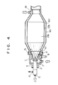
- Fig. 4 is a view illustrating a combustion chamber in a third embodiment, in cross-section.
- In an exhaust gas purifier of the present invention, two gas outlets of a four-way valve are connected to two filter elements which are received in a case, and one of two gas inlets thereof is connected to an exhaust pipe from an engine and the other is connected to a combustion chamber. This four-way valve switches over a gas flow through one of the filter elements from the exhaust gas from the engine to preheated gas from a burner to provide regeneration.
- The operation of this exhaust gas purifier is described below.
- During the normal operation of the engine, an elliptical vane of the four-way valve is at a neutral position with respect to the two gas outlets, so that the exhaust gas flowing into the four-way valve flow to the filter elements from the respective gas outlets, with particulates being filtered off and purified exhaust gas being exhausted to the air.
- When particulates have accumulated in the filter elements so that they must be regenerated, the elliptical vane in the four-way valve is moved so that one of the gas outlets communicates with the gas inlet connected to the exhaust pipe from the engine, and the other communicates with the gas inlet connected to the combustion chamber. The former gas outlet leads the exhaust gas to the corresponding filter element to continue capturing particulates, and the latter gas outlet leads preheated gas from the burner, which has started combustion, to the other filter element to regenerate it. After one of the filter elements has been completely regenerated, the elliptical vane is rotated so as to cause the exhaust gas to flow through the filter element which has regenerated and the preheated gas to flow through the other filter element to regenerate it. Therefore, no particulates are exhausted to the air during the regeneration, the preheated gas from the burner is supplied to the filter elements after being agitated by the four-way valve so that its temperature is made to be uniform and it thus heats the filter elements uniformly, and no large thermal stresses occur so that the filter elements do not rupture.
- The exhaust gas purifier of the present invention allows an engine to be operated with a very low back pressure during normal operation in which the two filter elements are being used, and thus can maintain the low penalty of engine power, and is an effective purifier which does not exhaust unpurified exhaust gas to the air during regeneration. In addition, since the exhaust gas from the engine and the combustion gas from the burner are isolated from each other by the four-way valve, the exhaust gas is not unnecessarily heated. Furthermore, since filter elements made of fiber ceramics with a small heat capacity are used, the size of the burner can be greatly reduced, resulting in the possibility of a great reduction in fuel consumption. Since the temperature gradient produced when the filter elements are heated is also very small, and thus does not create any problems concerning fracture and melting, regeneration can be economically and safely performed.
- A first embodiment of the present invention is described below.
- Fig. 1 shows a first embodiment of the present invention in which
reference numeral 1 denotes a burner;reference numeral 2, a nozzle; reference numeral 3, a burner body; andreference numeral 4, a stabilizer. Thenozzle 2 has an atomization air supply 5 and a fuel supply 6 which are connected to an air compressor (not shown) and an oil pump (not shown), respectively. The burner body 3 has acombustion air supply 7 which has an annular shape that is concentric with thenozzle 2. Thestabilizer 4, which has a funnel shape, extends from thecombustion air supply 7 to a position in front of thenozzle 2. Thestabilizer 4 is provided with aswirler 8. Aspark plug 9 connected to an induction coil (not shown) passes through the burner body 3 and thestabilizer 4 as far as a position near thenozzle 2. An annularintake air supply 10 is provided around the periphery of thestabilizer 4 in the vicinity of the top of the burner body 3. - A
combustion chamber 13 comprising an outer sleeve 11 and aninner sleeve 12 is connected to the front of theburner 1. Athermal insulator 14 made of ceramic fibers is charged between the outer sleeve 11 and theinner sleeve 12. The side of thecombustion chamber 13 opposite to theburner 1 is connected to apreheated air inlet 15 of a four-way valve 16. - Fig. 2 is a sectional view of the four-
way valve 16. - One side of a
cylinder 17 is opened to form a preheated air inlet to thecombustion chamber 13, and the other end is closed by aback cover 19 provided around abearing 18.Gas outlets preheated air inlet 15 so as to be opposite to each other in the direction perpendicular to the axis of thecylinder 17. Ashaft 21 is inserted into thecylinder 17, passing through thebearing 18, so as to be coaxial with thecylinder 17. Anelliptical vane 22 is fixed to one end of theshaft 21, and acylindrical vane 23 is fixed to the other end of theshaft 21, near theback cover 19 in thecylinder 17. The elliptical andcylindrical vanes slots circular rings slots shaft 21 passed through thebearing 18 is connected to amotor 28. Agas inlet 29 opens at acylinder 17 in position between theelliptical vane 22 and thecylindrical vane 23, and is connected to anexhaust pipe 30 from the engine. - In Fig 1, connection pipes 31a, 31b are connected to the
gas outlets cylindrical cases cylinder 17. Thecases filter elements mats filter elements cells plugs cases exhaust pipe 38 through anexhaust outlet cover 38. - A description will now be made to the operation in the above-described configuration of the first embodiment.
- During normal operation of the engine, the shorter axis of the ellipse of the
elliptical vane 22 in the four-way valve 16 is parallel to the line connecting theopposite gas outlets way valve 16 is at a neutral position so as to cause all the openings of thecylinder 17 to communicate with each other. In this case, the exhaust gas from the engine are branched to the connection pipes 31a, 31b from thegas outlets way valve 16, dispersed over the entire surfaces of thefilter elements cells cells outlet cover 38, are collected in theexhaust pipe 39, and are exhausted to the air. During this operation, air continuously flows from thecombustion air supply 7 and/or theintake air supply 10 of theburner 1 so that no exhaust gas enter theburner 1. During this time, atomization air and fuel are cut off at an intermediate position of the path by a solenoid valve (not shown). The exhaust gases introduced in the four-way valve 16 are prevented from leaking from theback cover 19 by the circular rings 27 provided on thecylindrical vane 23. - A description will now be made to the procedure used when the
filter elements - The
motor 28 is first energized to rotate theshaft 21. When theelliptical vane 22 has rotated 90° from its neutral position, the motor is stopped. In this state, thecombustion chamber 13 and theexhaust pipe 30 from the engine communicate with the connection pipes 31a and 31b, respectively. Then a high voltage of about 10,000 V is applied to thespark plug 9 to produce an electric discharge with spark at the top thereof. Several seconds later, the solenoid valves which had cut off the atomization air and the fuel are simultaneously opened to supply the air and the fuel, to which pressure is applied by the air compressor and the oil pump, respectively, to theatomizing nozzle 2. The fuel is atomized by the atomization air in theatomizing nozzle 2 and is then blown into thecombustion chamber 13. The fuel is then uniformly mixed with combustion air which has been forced into a vortex flow by being passed though the swirler of thestabilizer 4. At this point, the atomized fuel is ignited by the discharge of thespark plug 9 to form a flame. The flame is stabilized in front of theburner 1 by the vortex flow of thestabilizer 4 so that a good combustion state is maintained in thecombustion chamber 13. The intake air is blown out from theintake air supply 10 which is provided in the periphery of thestabilizer 4, passes along the inner periphery of thecombustion chamber 13 while surrounding the flame, and reaches theinlet 15 of the four-way valve 16. The burned gas and the intake air are well mixed during the time they pass through thecombustion chamber 13 and the four-way valve 16, to form a high-temperature gas which contains a large amount of oxygen and is at a controlled temperature, and which is then passed to theinlet cover 32a through the connection pipe 31a. The high-temperature gas is uniformly dispersed over the entire surface of thefilter element 34a in theinlet cover 32a and flows through thefilter element 34a. During this time, thefilter element 34a and the particulates accumulated therein are heated to about 600°C so that the particulates start to be incinerated. The burned gas generated by the combustion is passed through theoutlet cover 38 and exhausted to the air through theexhaust pipe 39. The temperature of the preheated gas can be controlled by controlling the amount of combustion in theburner 1 or the amount of intake air, or by controlling both amounts, whereby the oxygen content can be controlled. The exhaust gas from the engine is passed through thegas inlet 29 and then between theelliptical vane 22 and thecylindrical vane 23, and flow into theinlet cover 32b through the other connection pipe 31b while cooling theelliptical vane 22 and theshaft 21 which are at a high temperature because of the preheated gas. The exhaust gas continues to be filtered by thefilter element 34b, with particulates being accumulated in thecells 36b. After this process has been completed over a period of several minutes, the motor is inversely energized so as to reverse theshaft 21 by 180°. In this state, thecombustion chamber 13 and thegas inlet 29 are communicated with the connection pipes 31b, 31a, respectively, in a manner opposite to the above-described operation. Therefore, the preheated gas from theburner 1 and the exhaust gas from the engine are switched so that the engine exhaust gas is passed through thefilter element 34a which has been regenerated by the burning of the particulates therein by the flow of the preheated gas, and the preheated gas is passed through thefilter element 34b in which particulates have been accumulated by the flow of the engine exhaust gas. Consequently, the particulates accumulated in thefilter element 34b are rapidly heated to 600°C, which is their ignition temperature, and thus start to be incinerated. At the same time, particulates are again accumulated in the regeneratedfilter element 34a. After this operation has been completed over a period of several minutes, the motor is again energized to rotate theshaft 21 by 90° and return theelliptical vane 22 to its initial neutral position. - Therefore, the two filter elements are generally operated at the same time, producing extremely low back pressure, and this purifier can thus be operated without imposing any load on the engine. On the other hand, since one of the filter elements is operated for regeneration purposes and the other is operated as a filter during the regeneration, the exhaust gases from the engine are always passed through the
filter element burner 1 carrying out complete combustion passes through the four-way valve 16 and the connection pipe 31a or 31b, and is dispersed over the entire surface of thefilter element inlet cover filter element elliptical rings 26 provided in theelliptical vane 22 in the four-way valve 16, the exhaust gas will not be mixed with the preheated gas of theburner 1. Although the four-way valve 16 is heated during the operation of the engine, particularly during the regeneration, theelliptical rings 26 and the circular rings 27 respectively provided in theelliptical vane 22 and thecylindrical vane 23 prevent any leakage of the gas, as well as preventing stoppage of the rotation of these vanes due to any increase in friction resulting from the difference in thermal expansion between the vanes and thecylinder 17. - A second embodiment of the present invention is described below.
- Fig. 3 is a longitudinal sectioned view of another embodiment of the present invention in which members that are the same as those in the first embodiment are denoted by the same reference numerals and are thus not described below. In the drawing,
reference numerals cases connection pipes 31c, 31d, on the lines tangent to the outer shapes of the inlet covers. Consequently, the gas that has passed through theconnection pipe 31c or 31d flows into thefilter element inlet cover filter element filter element filter element filter element filter element mats - A third embodiment is described below with reference to Fig. 4 in which members that are the same as those in the first embodiment are denoted by the same reference numerals and are thus not described below. In this embodiment, a
combustion chamber 13b has a dual structure comprising an outer sleeve 11b and aninner sleeve 12b, and a space formed between the outer sleeve 11b and theinner sleeve 12b serves as anintake air passage 40. An intakeair connection portion 41 is provided on the side of theintake air passage 40 near thepreheated gas inlet 15 of the four-way valve 16, and the other side communicates with theintake air inlet 10. During regeneration, the combustion is started in theburner 1 so as to form a flame which starts to heat theinner sleeve 12b. At the same time, the intake air flows through theintake air passage 40 while cooling theinner sleeve 12b, blown out into thecombustion chamber 13b from theintake air inlet 10, mixed with the flame, and sent as a preheated gas at a given temperature to the filter element to be regenerated. In this embodiment, the temperature of the preheated gas is kept at 600°C. - When the
combustion chamber 13b of this embodiment is used, the fuel consumption of the burner in a stationary state is smaller than that immediately after the ignition, resulting in a smaller amount of fuel being consumed than in the first embodiment. In addition, the temperature of the outer sleeve 11b is increased by 50°C or less by the combustion of the burner because no heat of combustion of the burner is unnecessarily used for heating the thermal insulators. Therefore, the heat of the burner is most efficiently used for heating the filter elements, with a remarkable effect of thermal insulation being produced. - The present invention provides an effective purifier which uses two filter elements during normal operation of an engine and thus allows the engine to be operated with very low back pressure, ensuring high engine efficiency, and preventing emission of any gas not purified during regeneration of the filter elements. In addition, since the exhaust gas from the engine is isolated from the preheated gas from a burner by a four-way valve during regeneration, the exhaust gas needs not be heated. Furthermore, since each of the filter elements comprises fiber ceramics having a small heat capacity, the size of the burner and the fuel consumption can be greatly reduced.
Claims (7)
Applications Claiming Priority (6)
| Application Number | Priority Date | Filing Date | Title |
|---|---|---|---|
| JP62066411A JPS63235612A (en) | 1987-03-20 | 1987-03-20 | Diesel exhaust gas cleaning device |
| JP66410/87 | 1987-03-20 | ||
| JP66411/87 | 1987-03-20 | ||
| JP6641087A JPS63235775A (en) | 1987-03-20 | 1987-03-20 | Selector valve |
| JP206702/87 | 1987-08-20 | ||
| JP20670287A JPS6453010A (en) | 1987-08-20 | 1987-08-20 | Exhaust emission controlling burner |
Publications (3)
| Publication Number | Publication Date |
|---|---|
| EP0283240A2 true EP0283240A2 (en) | 1988-09-21 |
| EP0283240A3 EP0283240A3 (en) | 1989-01-25 |
| EP0283240B1 EP0283240B1 (en) | 1992-09-30 |
Family
ID=27299119
Family Applications (1)
| Application Number | Title | Priority Date | Filing Date |
|---|---|---|---|
| EP19880302237 Expired - Lifetime EP0283240B1 (en) | 1987-03-20 | 1988-03-15 | Diesel engine exhaust gas particle filter |
Country Status (5)
| Country | Link |
|---|---|
| US (1) | US4840028A (en) |
| EP (1) | EP0283240B1 (en) |
| AU (1) | AU597479B2 (en) |
| CA (1) | CA1308361C (en) |
| DE (1) | DE3874924T2 (en) |
Cited By (15)
| Publication number | Priority date | Publication date | Assignee | Title |
|---|---|---|---|---|
| DE3837472A1 (en) * | 1988-11-04 | 1990-05-10 | Kloeckner Humboldt Deutz Ag | PARTICLE FILTER SYSTEM |
| AU597479B2 (en) * | 1987-03-20 | 1990-05-31 | Matsushita Electric Industrial Co., Ltd. | A purifier of diesel particulates in exhaust gas |
| US5199257A (en) * | 1989-02-10 | 1993-04-06 | Centro Sviluppo Materiali S.P.A. | Device for removal of particulates from exhaust and flue gases |
| WO1997003277A1 (en) * | 1995-07-12 | 1997-01-30 | Firma Carl Freudenberg | Device for purifying waste gas from a mixture-compressing internal combustion engine |
| US6370871B2 (en) * | 1998-12-22 | 2002-04-16 | Toyota Jidosha Kabushiki Kaisha | Internal combustion engine having lean NOx catalyst |
| WO2003004134A2 (en) * | 2001-06-30 | 2003-01-16 | Gerd Gaiser | Method for purifying exhaust gases |
| FR2840354A1 (en) * | 2002-06-04 | 2003-12-05 | Jean Claude Fayard | EXHAUST GAS FILTERING DEVICE FOR A DIESEL ENGINE WITH CONTROLLED OBSTRUCTION VARIABLE FILTRATION SURFACE |
| EP1396616A1 (en) * | 2002-09-03 | 2004-03-10 | Arvin Technologies, Inc. | Exhaust processor comprising a first and a second soot filter and a heater for regeneration |
| WO2010144006A1 (en) * | 2009-06-11 | 2010-12-16 | Stt Emtec Ab | Exhaust gas recirculation system |
| CN101694173B (en) * | 2009-10-16 | 2011-09-07 | 徐和平 | Exhaust purifier of diesel engine |
| WO2013171409A1 (en) * | 2012-05-15 | 2013-11-21 | Valeo Systemes De Controle Moteur | Valve for controlling a flow of fluid, including a rotary closure means |
| CN103541788A (en) * | 2013-11-12 | 2014-01-29 | 上海三一重机有限公司 | Filtering device for engine exhaust gas and engineering machine with same |
| DE102012017278A1 (en) | 2012-08-31 | 2014-03-06 | Volkswagen Aktiengesellschaft | Drive device for motor car, has controllable switching unit arranged and equipped on connection point to selectively conduct exhaust gas partial stream guided by particle filter over exhaust gas return line for air line or into exhaust line |
| EP3660290A1 (en) * | 2018-11-27 | 2020-06-03 | Akrapovic d.d. | Gas flow and sound control valve and exhaust gas system |
| IT202000017989A1 (en) * | 2020-07-24 | 2022-01-24 | Marelli Europe Spa | HEATER DEVICE FOR AN EXHAUST SYSTEM OF AN INTERNAL COMBUSTION ENGINE |
Families Citing this family (45)
| Publication number | Priority date | Publication date | Assignee | Title |
|---|---|---|---|---|
| US5212948A (en) * | 1990-09-27 | 1993-05-25 | Donaldson Company, Inc. | Trap apparatus with bypass |
| US5284016A (en) * | 1992-08-28 | 1994-02-08 | General Motors Corporation | Exhaust gas burner reactor |
| US5339630A (en) * | 1992-08-28 | 1994-08-23 | General Motors Corporation | Exhaust burner catalyst preheater |
| US5320523A (en) * | 1992-08-28 | 1994-06-14 | General Motors Corporation | Burner for heating gas stream |
| US5444976A (en) * | 1994-06-27 | 1995-08-29 | General Motors Corporation | Catalytic converter heating |
| US5547641A (en) * | 1995-01-10 | 1996-08-20 | Caterpillar Inc. | Catalytic converter exhaust section for an internal combustion engine |
| US5616350A (en) * | 1995-04-10 | 1997-04-01 | Cincinnati Milacron Inc. | Dual flow divider with diverter valve |
| US5771683A (en) * | 1995-08-30 | 1998-06-30 | Southwest Research Institute | Active porous medium aftertreatment control system |
| KR100418159B1 (en) * | 1996-08-16 | 2004-04-17 | 김대식 | A Compact High Temperature Air Purifier |
| US6233926B1 (en) * | 2000-03-01 | 2001-05-22 | Illinois Valley Holding Company | Apparatus and method for filtering particulate in an exhaust trap |
| US6572357B2 (en) | 2001-02-27 | 2003-06-03 | Illinois Valley Holding Comany | Apparatus for manufacturing monolithic cross flow particulate traps |
| US6735940B2 (en) * | 2002-07-11 | 2004-05-18 | Fleetguard, Inc. | Adsorber aftertreatment system having dual adsorbers |
| US7269942B2 (en) * | 2003-05-15 | 2007-09-18 | Illinois Valley Holding Company | Wall flow particulate trap system |
| GB2408470B (en) * | 2003-11-25 | 2007-06-13 | Arvin Internat | An internal combustion engine exhaust system |
| US7628011B2 (en) * | 2004-01-13 | 2009-12-08 | Emcon Technologies Llc | Emission abatement assembly and method of operating the same |
| US7297174B2 (en) * | 2004-02-11 | 2007-11-20 | Et Us Holdings, Llc | Particulate filter assembly |
| DE102004008415A1 (en) * | 2004-02-20 | 2005-09-01 | Arvin Technologies, Inc., Troy | Device for cleaning vehicle exhaust gases, in particular diesel soot filters |
| DE102004013458A1 (en) * | 2004-03-18 | 2005-10-20 | Arvin Technologies Inc | Device for cleaning vehicle exhaust gases |
| DE102004016690A1 (en) * | 2004-04-05 | 2005-10-27 | Arvin Technologies, Inc., Troy | Device for cleaning vehicle exhaust gases, in particular diesel soot filters, and vehicle with corresponding device |
| US7332016B2 (en) * | 2004-07-30 | 2008-02-19 | Caterpillar Inc. | Particulate trap with selective blocking element |
| US20060048500A1 (en) * | 2004-09-09 | 2006-03-09 | Loving Ronald E | Engine exhaust re-burner system |
| AT501042B8 (en) * | 2005-02-02 | 2007-02-15 | Pankl Emission Control Systems | DEVICE FOR CLEANING MOTOR VEHICLE EXHAUST GASES |
| FR2881793B1 (en) * | 2005-02-04 | 2007-05-11 | Melchior Jean F | INTERNAL COMBUSTION ALTERNATIVE MOTOR AND METHOD FOR REMOVING BURNER GAS PARTICLES FOR SUCH AN ALTERNATIVE ENGINE |
| US20060218902A1 (en) * | 2005-03-31 | 2006-10-05 | Solar Turbines Incorporated | Burner assembly for particulate trap regeneration |
| US20060254260A1 (en) * | 2005-05-16 | 2006-11-16 | Arvinmeritor Emissions Technologies Gmbh | Method and apparatus for piezoelectric injection of agent into exhaust gas for use with emission abatement device |
| US7246005B2 (en) * | 2005-06-07 | 2007-07-17 | Arvin Technologies, Inc. | Method and apparatus for controlling a component by feed-forward closed-loop controller state modification |
| US7332142B2 (en) * | 2005-06-17 | 2008-02-19 | Emcon Tehnologies Germany (Augsburg) Gmbh | Method and apparatus for bubble injection of agent into exhaust gas for use with emission abatement device |
| US7481048B2 (en) * | 2005-06-30 | 2009-01-27 | Caterpillar Inc. | Regeneration assembly |
| US7406822B2 (en) * | 2005-06-30 | 2008-08-05 | Caterpillar Inc. | Particulate trap regeneration system and control strategy |
| US20070158466A1 (en) * | 2005-12-29 | 2007-07-12 | Harmon Michael P | Nozzle assembly |
| US20070228191A1 (en) * | 2006-03-31 | 2007-10-04 | Caterpillar Inc. | Cooled nozzle assembly for urea/water injection |
| US20070235556A1 (en) * | 2006-03-31 | 2007-10-11 | Harmon Michael P | Nozzle assembly |
| US7980061B2 (en) * | 2008-03-04 | 2011-07-19 | Tenneco Automotive Operating Company Inc. | Charged air bypass for aftertreatment combustion air supply |
| FR2990740B1 (en) * | 2012-05-15 | 2014-05-02 | Valeo Sys Controle Moteur Sas | FLUID CIRCULATION VALVE, IN PARTICULAR FOR A MOTOR VEHICLE, AND THERMAL CONDITIONING DEVICE COMPRISING SUCH A VALVE |
| US20140053519A1 (en) * | 2012-08-27 | 2014-02-27 | Wen-Lo Chen | Device for combustion and purification treatment of automobile smoky exhaust |
| US9352276B2 (en) | 2013-05-07 | 2016-05-31 | Tenneco Automotive Operating Company Inc. | Exhaust mixing device |
| US9364790B2 (en) | 2013-05-07 | 2016-06-14 | Tenneco Automotive Operating Company Inc. | Exhaust mixing assembly |
| US9289724B2 (en) | 2013-05-07 | 2016-03-22 | Tenneco Automotive Operating Company Inc. | Flow reversing exhaust gas mixer |
| US9291081B2 (en) | 2013-05-07 | 2016-03-22 | Tenneco Automotive Operating Company Inc. | Axial flow atomization module |
| US9314750B2 (en) | 2013-05-07 | 2016-04-19 | Tenneco Automotive Operating Company Inc. | Axial flow atomization module |
| US9334781B2 (en) | 2013-05-07 | 2016-05-10 | Tenneco Automotive Operating Company Inc. | Vertical ultrasonic decomposition pipe |
| US9534525B2 (en) | 2015-05-27 | 2017-01-03 | Tenneco Automotive Operating Company Inc. | Mixer assembly for exhaust aftertreatment system |
| DE102016220417A1 (en) * | 2016-10-18 | 2018-04-19 | Hug Engineering Ag | Separator and method of operating a separator |
| UA120644C2 (en) | 2017-10-27 | 2020-01-10 | Євген Олександрович Баранник | METHOD AND DEVICE FOR ULTRASOUND MEASUREMENT AND VISUALIZATION OF EFFICIENCY OF BIOLOGICAL TISSUES IN REAL TIME |
| CN113006915B (en) * | 2021-03-26 | 2022-08-02 | 重庆汽车消声器有限责任公司 | Noise-reduction environment-friendly silencer for small-tonnage internal combustion engine |
Citations (10)
| Publication number | Priority date | Publication date | Assignee | Title |
|---|---|---|---|---|
| FR958836A (en) * | 1950-03-21 | |||
| FR2300277A1 (en) * | 1975-02-04 | 1976-09-03 | Casem Lumello Carlo Francesco | Four way mixing valve - has rotatable valve member with oblique partitions controlling lateral inlets |
| US4373330A (en) * | 1981-06-29 | 1983-02-15 | General Motors Corporation | Diesel engine dual path exhaust cleaner and burner system |
| US4381643A (en) * | 1981-08-03 | 1983-05-03 | General Motors Corporation | Diesel exhaust cleaner and burner system with constant burner air mixture supply |
| DE3204176A1 (en) * | 1982-02-06 | 1983-08-11 | Forschungsgesellschaft für Energietechnik und Verbrennungsmotoren mbH, 5100 Aachen | Device for reducing the particulate emission of diesel engines by after-treatment of the exhaust gases |
| EP0087067A1 (en) * | 1982-02-16 | 1983-08-31 | Matsushita Electric Industrial Co., Ltd. | Exhaust gas filter and method of making the same |
| EP0121445A1 (en) * | 1983-04-05 | 1984-10-10 | Ngk Insulators, Ltd. | Multi-channel body |
| JPS60184917A (en) * | 1984-03-02 | 1985-09-20 | Hitachi Ltd | Device for decreasing diesel particulates |
| EP0207446A1 (en) * | 1985-06-26 | 1987-01-07 | Isuzu Motors Limited | Apparatus for regeneration of a particulate filter in diesel engine |
| DE8701816U1 (en) * | 1987-02-06 | 1987-04-09 | Man Technologie Gmbh, 8000 Muenchen, De |
Family Cites Families (10)
| Publication number | Priority date | Publication date | Assignee | Title |
|---|---|---|---|---|
| US4195063A (en) * | 1974-09-03 | 1980-03-25 | Matsushita Electric Industrial Co., Ltd. | Catalyst element for cleaning exhaust gases |
| US4169491A (en) * | 1977-11-18 | 1979-10-02 | Bajka Engineering Enterprises | Three port two-way diverter valve with integral drain on one output port |
| DE2902364C2 (en) * | 1979-01-22 | 1983-03-24 | Klein, Schanzlin & Becker Ag, 6710 Frankenthal | Transfer tube |
| JPS56118514A (en) * | 1980-02-25 | 1981-09-17 | Nippon Soken Inc | Cleaner for carbon particles of internal combustion engine |
| JPS5779209A (en) * | 1980-11-01 | 1982-05-18 | Nippon Denso Co Ltd | Exhaust gas purifier |
| JPS58101210A (en) * | 1981-12-10 | 1983-06-16 | Nippon Soken Inc | Exhaust gas particle purifier in internal-combustion engine |
| US4566628A (en) * | 1984-03-02 | 1986-01-28 | Tekmar Angewandte Elektronik Gmbh & Co. Kg | Method of and system for controlling the ratio between the water flow rate in the primary circuit and the water flow rate in the secondary circuit of a hot water heating system |
| JPS6111415A (en) * | 1984-06-27 | 1986-01-18 | Mitsubishi Electric Corp | On-vehicle combustion device |
| EP0213725A3 (en) * | 1985-08-05 | 1987-07-29 | BREHK Ventures | Method and apparatus for trapping and incinerating particulate matter found in diesel engine exhaust |
| EP0283240B1 (en) * | 1987-03-20 | 1992-09-30 | Matsushita Electric Industrial Co., Ltd. | Diesel engine exhaust gas particle filter |
-
1988
- 1988-03-15 EP EP19880302237 patent/EP0283240B1/en not_active Expired - Lifetime
- 1988-03-15 US US07/170,437 patent/US4840028A/en not_active Expired - Lifetime
- 1988-03-15 DE DE19883874924 patent/DE3874924T2/en not_active Expired - Fee Related
- 1988-03-16 AU AU13170/88A patent/AU597479B2/en not_active Ceased
- 1988-03-16 CA CA 561559 patent/CA1308361C/en not_active Expired - Lifetime
Patent Citations (10)
| Publication number | Priority date | Publication date | Assignee | Title |
|---|---|---|---|---|
| FR958836A (en) * | 1950-03-21 | |||
| FR2300277A1 (en) * | 1975-02-04 | 1976-09-03 | Casem Lumello Carlo Francesco | Four way mixing valve - has rotatable valve member with oblique partitions controlling lateral inlets |
| US4373330A (en) * | 1981-06-29 | 1983-02-15 | General Motors Corporation | Diesel engine dual path exhaust cleaner and burner system |
| US4381643A (en) * | 1981-08-03 | 1983-05-03 | General Motors Corporation | Diesel exhaust cleaner and burner system with constant burner air mixture supply |
| DE3204176A1 (en) * | 1982-02-06 | 1983-08-11 | Forschungsgesellschaft für Energietechnik und Verbrennungsmotoren mbH, 5100 Aachen | Device for reducing the particulate emission of diesel engines by after-treatment of the exhaust gases |
| EP0087067A1 (en) * | 1982-02-16 | 1983-08-31 | Matsushita Electric Industrial Co., Ltd. | Exhaust gas filter and method of making the same |
| EP0121445A1 (en) * | 1983-04-05 | 1984-10-10 | Ngk Insulators, Ltd. | Multi-channel body |
| JPS60184917A (en) * | 1984-03-02 | 1985-09-20 | Hitachi Ltd | Device for decreasing diesel particulates |
| EP0207446A1 (en) * | 1985-06-26 | 1987-01-07 | Isuzu Motors Limited | Apparatus for regeneration of a particulate filter in diesel engine |
| DE8701816U1 (en) * | 1987-02-06 | 1987-04-09 | Man Technologie Gmbh, 8000 Muenchen, De |
Non-Patent Citations (1)
| Title |
|---|
| PATENT ABSTRACTS OF JAPAN, vol. 10, no. 29 (M-451)[2086], 5th February 1986; & JP-A-60 184 917 (HITACHI SEISAKUSHO K.K.) 20-09-1985 * |
Cited By (25)
| Publication number | Priority date | Publication date | Assignee | Title |
|---|---|---|---|---|
| AU597479B2 (en) * | 1987-03-20 | 1990-05-31 | Matsushita Electric Industrial Co., Ltd. | A purifier of diesel particulates in exhaust gas |
| DE3837472A1 (en) * | 1988-11-04 | 1990-05-10 | Kloeckner Humboldt Deutz Ag | PARTICLE FILTER SYSTEM |
| DE3837472C2 (en) * | 1988-11-04 | 1998-09-24 | Deutz Ag | Particulate filter system |
| US5199257A (en) * | 1989-02-10 | 1993-04-06 | Centro Sviluppo Materiali S.P.A. | Device for removal of particulates from exhaust and flue gases |
| WO1997003277A1 (en) * | 1995-07-12 | 1997-01-30 | Firma Carl Freudenberg | Device for purifying waste gas from a mixture-compressing internal combustion engine |
| US6370871B2 (en) * | 1998-12-22 | 2002-04-16 | Toyota Jidosha Kabushiki Kaisha | Internal combustion engine having lean NOx catalyst |
| WO2003004134A2 (en) * | 2001-06-30 | 2003-01-16 | Gerd Gaiser | Method for purifying exhaust gases |
| WO2003004134A3 (en) * | 2001-06-30 | 2003-04-17 | Gerd Gaiser | Method for purifying exhaust gases |
| FR2840354A1 (en) * | 2002-06-04 | 2003-12-05 | Jean Claude Fayard | EXHAUST GAS FILTERING DEVICE FOR A DIESEL ENGINE WITH CONTROLLED OBSTRUCTION VARIABLE FILTRATION SURFACE |
| US7314501B2 (en) | 2002-06-04 | 2008-01-01 | Jean-Claude Fayard | Methods and device for filtration of exhaust gases for a diesel engine with a filtration surface which is variable by means of controlled obstruction |
| EP1396616A1 (en) * | 2002-09-03 | 2004-03-10 | Arvin Technologies, Inc. | Exhaust processor comprising a first and a second soot filter and a heater for regeneration |
| WO2010144006A1 (en) * | 2009-06-11 | 2010-12-16 | Stt Emtec Ab | Exhaust gas recirculation system |
| CN102803696A (en) * | 2009-06-11 | 2012-11-28 | Stt伊姆特克公司 | Exhaust gas recirculation system |
| CN101694173B (en) * | 2009-10-16 | 2011-09-07 | 徐和平 | Exhaust purifier of diesel engine |
| WO2013171409A1 (en) * | 2012-05-15 | 2013-11-21 | Valeo Systemes De Controle Moteur | Valve for controlling a flow of fluid, including a rotary closure means |
| FR2990739A1 (en) * | 2012-05-15 | 2013-11-22 | Valeo Sys Controle Moteur Sas | VALVE FOR CONTROLLING FLUID CIRCULATION, BY MEANS OF ROTARY SHUTTER |
| US9657843B2 (en) | 2012-05-15 | 2017-05-23 | Valeo Systemes De Controle Moteur | Valve for controlling a flow of fluid, including a rotary closure means |
| DE102012017278A1 (en) | 2012-08-31 | 2014-03-06 | Volkswagen Aktiengesellschaft | Drive device for motor car, has controllable switching unit arranged and equipped on connection point to selectively conduct exhaust gas partial stream guided by particle filter over exhaust gas return line for air line or into exhaust line |
| CN103541788A (en) * | 2013-11-12 | 2014-01-29 | 上海三一重机有限公司 | Filtering device for engine exhaust gas and engineering machine with same |
| EP3660290A1 (en) * | 2018-11-27 | 2020-06-03 | Akrapovic d.d. | Gas flow and sound control valve and exhaust gas system |
| WO2020109036A1 (en) * | 2018-11-27 | 2020-06-04 | Akrapovic D.D. | Gas flow and sound control valve and exhaust gas system |
| CN113302385A (en) * | 2018-11-27 | 2021-08-24 | 天蝎排气股份有限公司 | Gas flow and sound control valve and exhaust system |
| TWI754859B (en) * | 2018-11-27 | 2022-02-11 | 斯洛維尼亞商蠍子管有限責任公司 | An exhaust system of an internal combustion engine and a gas flow and sound control valve |
| CN113302385B (en) * | 2018-11-27 | 2023-08-29 | 天蝎排气股份有限公司 | Gas flow and sound control valve and exhaust system |
| IT202000017989A1 (en) * | 2020-07-24 | 2022-01-24 | Marelli Europe Spa | HEATER DEVICE FOR AN EXHAUST SYSTEM OF AN INTERNAL COMBUSTION ENGINE |
Also Published As
| Publication number | Publication date |
|---|---|
| AU597479B2 (en) | 1990-05-31 |
| DE3874924T2 (en) | 1993-04-01 |
| DE3874924D1 (en) | 1992-11-05 |
| US4840028A (en) | 1989-06-20 |
| AU1317088A (en) | 1988-10-20 |
| EP0283240B1 (en) | 1992-09-30 |
| CA1308361C (en) | 1992-10-06 |
| EP0283240A3 (en) | 1989-01-25 |
Similar Documents
| Publication | Publication Date | Title |
|---|---|---|
| US4840028A (en) | Purifier of diesel particulates in exhaust gas | |
| US4730455A (en) | Process and system for the regeneration of particulate filter traps | |
| US5671600A (en) | Method of reducing the NOx emission of a supercharged piston-type internal combustion engine | |
| US5904042A (en) | Diesel exhaust conditioning system | |
| US4858431A (en) | Apparatus for removing solid particles, especially soot particles, from the exhaust gas of an internal combustion engine | |
| KR20010093134A (en) | Filter for egr system heated by an enclosing catalyst | |
| WO1998058164A1 (en) | Anti-pollution system | |
| CN101405486A (en) | Methods and device for filtration of exhaust gases for a diesel engine with a filtration surface which is variable by means of controlled obstruction | |
| US6461398B2 (en) | Regenerable particle filter for the removal of soot particles from exhaust gases | |
| US4054417A (en) | Regenerative-filter-incinerator device | |
| US5014511A (en) | Filtration system for diesel engine exhaust-II | |
| US3802194A (en) | Exhaust gas cleaning device | |
| US8424291B2 (en) | Flame glow plug | |
| JPS6231165B2 (en) | ||
| EP0591180A1 (en) | Particulate filter trap for a diesel engine | |
| EP0151558A1 (en) | Particle filter for cleaning exhaust gas from internal combustion engines | |
| JPS5820918A (en) | Purifier of exhaust gas | |
| JPH06221137A (en) | Exhaust gas disposing device | |
| WO1997024516A1 (en) | Device for removing particulate materials from exhaust gas of diesel vehicles | |
| JP3078941B2 (en) | Exhaust gas treatment device | |
| CA2220210C (en) | Diesel exhaust conditioning system | |
| JP3078942B2 (en) | Exhaust gas treatment device | |
| JPH0532562B2 (en) | ||
| JP3078940B2 (en) | Exhaust gas treatment device | |
| JPH06173643A (en) | Exhaust gas treatment device |
Legal Events
| Date | Code | Title | Description |
|---|---|---|---|
| PUAI | Public reference made under article 153(3) epc to a published international application that has entered the european phase |
Free format text: ORIGINAL CODE: 0009012 |
|
| AK | Designated contracting states |
Kind code of ref document: A2 Designated state(s): DE FR GB |
|
| PUAL | Search report despatched |
Free format text: ORIGINAL CODE: 0009013 |
|
| AK | Designated contracting states |
Kind code of ref document: A3 Designated state(s): DE FR GB |
|
| 17P | Request for examination filed |
Effective date: 19890331 |
|
| 17Q | First examination report despatched |
Effective date: 19891123 |
|
| GRAA | (expected) grant |
Free format text: ORIGINAL CODE: 0009210 |
|
| AK | Designated contracting states |
Kind code of ref document: B1 Designated state(s): DE FR GB |
|
| REF | Corresponds to: |
Ref document number: 3874924 Country of ref document: DE Date of ref document: 19921105 |
|
| ET | Fr: translation filed | ||
| PLBE | No opposition filed within time limit |
Free format text: ORIGINAL CODE: 0009261 |
|
| STAA | Information on the status of an ep patent application or granted ep patent |
Free format text: STATUS: NO OPPOSITION FILED WITHIN TIME LIMIT |
|
| 26N | No opposition filed | ||
| REG | Reference to a national code |
Ref country code: GB Ref legal event code: 746 Effective date: 19950224 |
|
| REG | Reference to a national code |
Ref country code: FR Ref legal event code: D6 |
|
| REG | Reference to a national code |
Ref country code: GB Ref legal event code: IF02 |
|
| PGFP | Annual fee paid to national office [announced via postgrant information from national office to epo] |
Ref country code: FR Payment date: 20040309 Year of fee payment: 17 |
|
| PGFP | Annual fee paid to national office [announced via postgrant information from national office to epo] |
Ref country code: GB Payment date: 20040310 Year of fee payment: 17 |
|
| PGFP | Annual fee paid to national office [announced via postgrant information from national office to epo] |
Ref country code: DE Payment date: 20040325 Year of fee payment: 17 |
|
| PG25 | Lapsed in a contracting state [announced via postgrant information from national office to epo] |
Ref country code: GB Free format text: LAPSE BECAUSE OF NON-PAYMENT OF DUE FEES Effective date: 20050315 |
|
| PG25 | Lapsed in a contracting state [announced via postgrant information from national office to epo] |
Ref country code: DE Free format text: LAPSE BECAUSE OF NON-PAYMENT OF DUE FEES Effective date: 20051001 |
|
| GBPC | Gb: european patent ceased through non-payment of renewal fee |
Effective date: 20050315 |
|
| PG25 | Lapsed in a contracting state [announced via postgrant information from national office to epo] |
Ref country code: FR Free format text: LAPSE BECAUSE OF NON-PAYMENT OF DUE FEES Effective date: 20051130 |
|
| REG | Reference to a national code |
Ref country code: FR Ref legal event code: ST Effective date: 20051130 |