EP0282886A2 - Process for regulating the start temperature in a heat transfer system - Google Patents
Process for regulating the start temperature in a heat transfer system Download PDFInfo
- Publication number
- EP0282886A2 EP0282886A2 EP88103684A EP88103684A EP0282886A2 EP 0282886 A2 EP0282886 A2 EP 0282886A2 EP 88103684 A EP88103684 A EP 88103684A EP 88103684 A EP88103684 A EP 88103684A EP 0282886 A2 EP0282886 A2 EP 0282886A2
- Authority
- EP
- European Patent Office
- Prior art keywords
- flow
- temperature
- working medium
- energy
- circulating
- Prior art date
- Legal status (The legal status is an assumption and is not a legal conclusion. Google has not performed a legal analysis and makes no representation as to the accuracy of the status listed.)
- Granted
Links
- 238000000034 method Methods 0.000 title claims abstract description 25
- 230000001105 regulatory effect Effects 0.000 title claims description 5
- 238000010438 heat treatment Methods 0.000 claims description 26
- 230000005540 biological transmission Effects 0.000 claims description 12
- 230000001276 controlling effect Effects 0.000 claims description 3
- 238000005259 measurement Methods 0.000 claims description 2
- 238000005496 tempering Methods 0.000 claims 1
- 230000007704 transition Effects 0.000 claims 1
- 230000007423 decrease Effects 0.000 description 4
- 238000005338 heat storage Methods 0.000 description 2
- 238000004378 air conditioning Methods 0.000 description 1
- 230000033228 biological regulation Effects 0.000 description 1
- 238000001816 cooling Methods 0.000 description 1
- 230000007812 deficiency Effects 0.000 description 1
- 238000010586 diagram Methods 0.000 description 1
- 230000017525 heat dissipation Effects 0.000 description 1
- 238000009434 installation Methods 0.000 description 1
- 238000010327 methods by industry Methods 0.000 description 1
- 230000002250 progressing effect Effects 0.000 description 1
- 238000009423 ventilation Methods 0.000 description 1
- 238000010792 warming Methods 0.000 description 1
- 239000002918 waste heat Substances 0.000 description 1
- XLYOFNOQVPJJNP-UHFFFAOYSA-N water Substances O XLYOFNOQVPJJNP-UHFFFAOYSA-N 0.000 description 1
Images


Classifications
-
- F—MECHANICAL ENGINEERING; LIGHTING; HEATING; WEAPONS; BLASTING
- F24—HEATING; RANGES; VENTILATING
- F24D—DOMESTIC- OR SPACE-HEATING SYSTEMS, e.g. CENTRAL HEATING SYSTEMS; DOMESTIC HOT-WATER SUPPLY SYSTEMS; ELEMENTS OR COMPONENTS THEREFOR
- F24D19/00—Details
- F24D19/10—Arrangement or mounting of control or safety devices
- F24D19/1006—Arrangement or mounting of control or safety devices for water heating systems
- F24D19/1009—Arrangement or mounting of control or safety devices for water heating systems for central heating
- F24D19/1012—Arrangement or mounting of control or safety devices for water heating systems for central heating by regulating the speed of a pump
-
- G—PHYSICS
- G05—CONTROLLING; REGULATING
- G05D—SYSTEMS FOR CONTROLLING OR REGULATING NON-ELECTRIC VARIABLES
- G05D23/00—Control of temperature
- G05D23/19—Control of temperature characterised by the use of electric means
- G05D23/1919—Control of temperature characterised by the use of electric means characterised by the type of controller
-
- Y—GENERAL TAGGING OF NEW TECHNOLOGICAL DEVELOPMENTS; GENERAL TAGGING OF CROSS-SECTIONAL TECHNOLOGIES SPANNING OVER SEVERAL SECTIONS OF THE IPC; TECHNICAL SUBJECTS COVERED BY FORMER USPC CROSS-REFERENCE ART COLLECTIONS [XRACs] AND DIGESTS
- Y02—TECHNOLOGIES OR APPLICATIONS FOR MITIGATION OR ADAPTATION AGAINST CLIMATE CHANGE
- Y02B—CLIMATE CHANGE MITIGATION TECHNOLOGIES RELATED TO BUILDINGS, e.g. HOUSING, HOUSE APPLIANCES OR RELATED END-USER APPLICATIONS
- Y02B30/00—Energy efficient heating, ventilation or air conditioning [HVAC]
- Y02B30/70—Efficient control or regulation technologies, e.g. for control of refrigerant flow, motor or heating
Definitions
- the invention relates to a method for controlling the flow temperature of the working medium of a plant for heat energy transmission, in particular for temperature control of the air in a closed space.
- a method is generally known in which the flow temperature of a heating system is controlled in accordance with the outside temperature.
- the intention is to adapt the heating output of the system to the constantly changing gradient between room temperature and outside temperature.
- this method is not able to take into account the heat storage capacity of the building masonry. This deficiency can lead to the fact that in the event of a fall in the weather after a longer heating period, the system is quickly brought to an increased heating capacity, although the heat stored in the masonry would initially allow the heating energy to be completely or at least partially dispensed with.
- a rapid rise in temperature after a long cold period leads to an equally rapid decrease in heating output, even though the masonry is still very cold and generally heats up much more slowly than the outside air.
- Outside temperature sensors have become known which are embedded in the masonry, but these sensors only detect the temperature of the masonry in its immediate vicinity giving. As a result, the meaningfulness of their measurements for the entire building complex is questionable.
- the invention is based on the object of specifying a method for controlling the flow temperature which takes into account secondary influences, for example heat stored in the masonry, and internal loads on the control of the energy requirement of a room.
- the solution is to measure the flow of energy consumed in the working medium circuit and then determine the flow temperature in the working medium circuit using a system-specific three-dimensional block of characteristics, the dimensions of which are determined by the flow and return temperature as well as the circulating flow of the working medium in the system.
- a load level in the heating operation of a system results from the respective gradient between room temperature and outside temperature.
- a certain flow temperature is assigned to each load level.
- the actual heat loss flow in the heating circuit can be calculated for each load level from the difference between the flow and return temperatures as well as the circulating flow, which is therefore also assigned a specific flow temperature.
- the actual heat loss flow in the heating circuit is measured and the associated flow temperature is then determined in each case.
- the influences by the heat storage capacity of the masonry on the control of the flow temperature and the heating power of a system can be taken into account in full. This results in savings in heating energy and an increase in heating comfort.
- the weather sensor which is indispensable in conventional flow temperature control methods, including the measured value transmission lines, is no longer required.
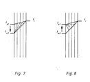
- the operation of the system according to FIG. 6 is as follows: It is assumed that the heating system has adjusted itself to an outside temperature t a1 on a mild winter day. The temperature gradient from t i to t a1 is small, as is the heat dissipation from heating surface 8. The product of the difference between the flow and return temperatures multiplied by the circulating volume flow corresponds to an integrated load level field within the system's characteristic curve block. If there is a drop in temperature from t a1 to t a2 ⁇ , then the heat stored in the masonry 12 is first consumed in layers from the outside, as is shown in simplified form in FIG. 7.
- the computer 4 now calculates the new, larger load step field on the basis of the new measured values of the sensors 1, 2 and 3 and shifts this within the stored characteristic curve block of the system towards a higher flow temperature until it can be fully integrated again.
- the setpoint value for the flow temperature that is automatically found and assigned to the new load level field is compared with the actual value measured by sensor 1.
- the computer 4 calculates an actuating signal which adjusts the mixing valve 5 via the motorized actuator 6 until the flow temperature corresponds to the new setpoint.
- the circulation pump 9 also receives a signal from the computer 4 for power adjustment, which is monitored on the basis of the measured values of the flow rate sensor 3.
- the layered heating of the masonry also takes a certain time. During this time, however, the heat output of the heating surfaces 8 also gradually decreases, as can be seen from the corresponding rise in the return temperature.
- the load level field becomes smaller and can be shifted in the direction of a lower flow temperature, which then results as a new setpoint when the new load level field is fully integrated in the characteristic block of the system.
- the mixing valve 5 and the circulation pump 9 are then controlled accordingly.
- the procedure is then basically the same, if the room temperature also changes due to internal loads.
- a decrease in the room temperature e.g. B. by ventilation, increases the temperature difference between flow and return and thus also the load level field, which is now shifted in the direction of a higher flow temperature.
- a warming of the room air e.g. by a larger number of people or by waste heat from non-heating devices, leads to a reduction in the temperature spread between flow and return and thus to a shift in the load level field in the direction of a lower flow temperature.
- the computer 4 controls the heat generator directly. Furthermore, the computer 4 takes into account their different specific heat when operating with media other than water. Moreover, it is easy to see that the invention is not only suitable for room air temperature control, but also for industrial heat consumers, for process engineering purposes and the like, i. H. for heating systems in the broadest sense. The process for cooling and air conditioning systems can also be easily reversed.
Abstract
Es wird ein Verfahren zur Energieübertragung beschrieben, bei welchem der in einem Arbeitsmittelkreis verbrauchte Energiemengenstrom gemessen und danach die Vorlauftemperatur im Arbeitsmittelkreis bestimmt wird.A method for energy transfer is described, in which the amount of energy flow consumed in a work medium circuit is measured and the flow temperature in the work medium circuit is then determined.
Description
Die Erfindung betrifft ein Verfahren zum Steuern der Vorlauftemperatur des Arbeitsmittels einer Anlage zur Wärmeenergieübertragung, insbesondere zur Temperierung der Luft in einem geschlossenen Raum.The invention relates to a method for controlling the flow temperature of the working medium of a plant for heat energy transmission, in particular for temperature control of the air in a closed space.
Allgemein bekannt ist ein Verfahren, bei welchem die Vorlauftemperatur einer Heizungsanlage nach Maßgabe der Außentemperatur gesteuert wird. Damit wird die Absicht verfolgt, die Heizleistung der Anlage dem ständig sich ändernden Gefälle zwischen Raumtemperatur und Außentemperatur anzupassen. Dieses Verfahren ist jedoch nicht in der Lage, das Wärmespeicherungsvermögen des Gebäudemauerwerks zu berücksichtigen. Dieser Mangel kann dazu führen, daß im Falle eines Wettersturzes nach einer längeren Wärmeperiode die Anlage schnell auf eine erhöhte Heizleistung gebracht wird, obwohl es die im Mauerwerk gespeicherte Wärme erlauben würde, zunächst ganz oder zumindest teilweise auf Heizenergie zu verzichten. Andererseits führt ein rascher Temperaturanstieg nach einer längeren Kälteperiode zu einer ebenso schnellen Zurücknahme der Heizleistung, obwohl das Mauerwerk noch stark ausgekühlt ist und sich in der Regel deutlich langsamer erwärmt als die Außenluft. Es sind zwar Außentemperaturfühler bekanntgeworden, welche in das Mauerwerk eingelassen werden, diese Fühler erfassen jedoch lediglich die Mauerwerkstemperatur in ihrer unmittelbaren Um gebung. Dadurch ist die Aussagekraft ihrer Messungen für den gesamten Gebäudekomplex zweifelhaft.A method is generally known in which the flow temperature of a heating system is controlled in accordance with the outside temperature. The intention is to adapt the heating output of the system to the constantly changing gradient between room temperature and outside temperature. However, this method is not able to take into account the heat storage capacity of the building masonry. This deficiency can lead to the fact that in the event of a fall in the weather after a longer heating period, the system is quickly brought to an increased heating capacity, although the heat stored in the masonry would initially allow the heating energy to be completely or at least partially dispensed with. On the other hand, a rapid rise in temperature after a long cold period leads to an equally rapid decrease in heating output, even though the masonry is still very cold and generally heats up much more slowly than the outside air. Outside temperature sensors have become known which are embedded in the masonry, but these sensors only detect the temperature of the masonry in its immediate vicinity giving. As a result, the meaningfulness of their measurements for the entire building complex is questionable.
Darüber hinaus ist eine solche Anlage selbstverständlich überfordert, wenn sie auch noch die inneren Lasten eines Gebäudekomplexes berücksichtigen soll. Um den möglicherweise zusätzlichen Verlust oder Zugewinn von Wärmeenergie durch nichtheiztechnische Installationen auszugleichen, müssen in diesem Fall zusätzliche Steuerungs- oder Regelgeräte verwendet werden.In addition, such a system is of course overwhelmed if it should also take into account the internal loads of a building complex. In this case, additional control or regulating devices have to be used to compensate for the possible additional loss or gain of thermal energy due to non-heating installations.
Der Erfindung liegt die Aufgabe zu Grunde, ein Verfahren zum Steuern der Vorlauftemperatur anzugeben, welches Nebeneinflüsse, beispielsweise im Mauerwerk gespeicherte Wärme sowie innere Lasten auf die Steuerung des Energiebedarfs eines Raumes berücksichtigt.The invention is based on the object of specifying a method for controlling the flow temperature which takes into account secondary influences, for example heat stored in the masonry, and internal loads on the control of the energy requirement of a room.
Die Lösung besteht darin, daß der im Arbeitsmittelkreis verbrauchte Energiemengenstrom gemessen und danach die Vorlauftemperatur im Arbeitsmittelkreis mit Hilfe eines anlagenspezifischen dreidimensionalen Kennlinienblocks bestimmt wird, dessen Dimensionen durch die Vorlauf- und Rücklauftemperatur sowie den Umwälzmengenstrom des Arbeitsmittels der Anlage bestimmt sind.The solution is to measure the flow of energy consumed in the working medium circuit and then determine the flow temperature in the working medium circuit using a system-specific three-dimensional block of characteristics, the dimensions of which are determined by the flow and return temperature as well as the circulating flow of the working medium in the system.
Bekanntlich ergibt sich eine Laststufe im Heizbetrieb einer Anlage aus dem jeweiligen Gefälle zwischen Raumtemperatur und Außentemperatur. Jeder Laststufe ist laut Heizkurven-Diagramm eine bestimmte Vorlauftemperatur zugeordnet. Aus der Differenz zwischen Vorlauf- und Rücklauftemperatur sowie dem Umwälzmengenstrom läßt sich für jede Laststufe der tatsächliche Wärmeverluststrom im Heizkreis errechnen, dem somit ebenfalls eine bestimmte Vorlauftemperatur zugeordnet ist.As is known, a load level in the heating operation of a system results from the respective gradient between room temperature and outside temperature. According to the heating curve diagram, a certain flow temperature is assigned to each load level. The actual heat loss flow in the heating circuit can be calculated for each load level from the difference between the flow and return temperatures as well as the circulating flow, which is therefore also assigned a specific flow temperature.
Bei dem Verfahren nach der Erfindung wird der tatsächliche Wärmeverluststrom im Heizkreis gemessen und danach jeweils die zugeordnete Vorlauftemperatur bestimmt.In the method according to the invention, the actual heat loss flow in the heating circuit is measured and the associated flow temperature is then determined in each case.
Mit dem Verfahren nach der Erfindung lassen sich beispielsweise die Einflüsse durch das Wärmespeicherungsvermögen des Mauerwerks auf die Steuerung der Vorlauftemperatur und der Heizleistung einer Anlage im vollen Umfang berücksichtigen. Dadurch ergeben sich Einsparungen an Heizenergie und eine Steigerung des Heizkomforts. Außerdem entfällt der bei herkömmlichen Verfahren zur Vorlauftemperatursteuerung unverzichtbare Witterungsfühler einschließlich der Meßwert-Übertragungsleitungen.With the method according to the invention, for example, the influences by the heat storage capacity of the masonry on the control of the flow temperature and the heating power of a system can be taken into account in full. This results in savings in heating energy and an increase in heating comfort. In addition, the weather sensor, which is indispensable in conventional flow temperature control methods, including the measured value transmission lines, is no longer required.
An Hand der Figuren der Zeichnung wird nachstehend die Erfindung näher erläutert.
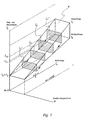
- Fig. 1 läßt den Ablauf des Verfahrens in einer Anlage mit gleichbleibendem Umwälzmengenstrom erkennen. In einem dreidimensionalen Koordinatensystem mit den Achswerten für die Temperaturen des Arbeitsmittels tH und der Außenluft ta sowie für den Umwälz-Mengenstrom m ist ein anlagenspezifischer Kennlinienblock K₁ eingezeichnet. Der Kennlinienblock wird durch die Summe aller Laststufenfelder einer Anlage gebildet. Ein Laststufenfeld ist das Produkt der Differenz zwischen einer Vorlauftemperatur tV und der dieser zugeordneten Rücklauftemperatur tR mit dem zugeordneten Umwälz-Mengenstrom m nach der Formel (tV - tR) × m. Die in dem Nomogramm als Querschnittsflächen dargestellten, in den dreidimensionalen Kennlinienblock K nicht integrierten Laststufenfelder L1ʹ bzw. L2ʹ entsprechen momentan gemessenen Wärmeverlusten. Sie werden innerhalb des Kennlinienblocks durch einen Rechner R (Fig. 6) solange verschoben, bis sie sich mit den flächengleichen, in den Kennlinienblock genau eingepaßten Laststufenfeldern L₁ bzw. L₂ decken. Die den eingepaßten Laststufen feldern zugeordneten Vorlauftemperaturen tV1 bzw. tV2 sind dann die gesuchten Werte.
- Fig. 2 zeigt den Verfahrensablauf in einer Anlage, in welcher einzelne Anlagenteile abgeschaltet werden und der Umwälzmengenstrom entsprechend reduziert wird. Der Vorgang ist im wesentlichen der gleiche wie in Fig. 1 dargestellt, lediglich die Größe der jeweiligen Laststufenfläche wird um einen Faktor vermindert, welcher der Verminderung des Umwälzmengenstromes, beispielsweise von m₄ bis m₁, entspricht.
- Fig. 3 zeigt prinzipiell den gleichen Vorgang wie in Fig. 1, jedoch unter dem Aspekt eines gedrosselten, aber ungeregelten Umwälzmengenstroms, wie er beispielsweise in Heizungsanlagen mit thermostatischen Heizkörperventilen, bei deren temperaturbedingtem Schließen jedoch bei mit voller Leistung weiterlaufender Umwälzpumpe auftritt. Hier wird ein nicht integriertes Laststufenfeld solange verschoben, bis sein Produkt aus der Differenz zwischen Vorlauf- und Rücklauftemperatur und dem Umwälzmengenstrom gleich ist dem entsprechenden Produkt eines integrierten flächengleichen Laststufenfeldes.
- Fig. 4 zeigt die Anwendung des Verfahrens in einer Anlage mit stufenweise geregeltem Umwälzmengenstrom. Der Gesamt-Kennlinienblock zerfällt entsprechend der Anzahl der Mengenstrom-Regelstufen in mehrere Einzelblöcke K₁, K₂, K₃, K₄. Innerhalb eines Einzelblocks, z. B. K₂, wird ein nicht integriertes Laststufenfeld L2ʹ in gleicher Weise nach L₂ verschoben wie in Fig. 1 dargestellt. Muß jedoch die Grenze zwischen zwei Einzelblöcken, z. B von K₃ nach K₄, übersprungen werden, dann wird das Produkt (tV - tR) × m des Laststufenfeldes L₃, zunächst dividiert durch den Wert m des neuen Einzelblocks K₄. Das dabei neu entstehende, nicht integrierte Laststufenfeld L₄, wird im neuen Einzelblock K₄ solange verschoben, bis es sich mit einem integrierten Laststufenfeld L₄ deckt.
- Fig. 5 zeigt eine weitere Variante des gleichen Grundprinzips, jedoch mit stufenlos geregeltem Umwälzmengenstrom. Sie ist gekennzeichnet von einer bestimmten linearen oder nichtlinearen Abnahme der Flächen der einzelnen integrierten Laststufenfelder im Bereich zwischen Vollast und Stillstand der Anlage. Auch hier wird ein nicht integriertes Laststufenfeld innerhalb eines Kennlinienblocks solange verschoben, bis sein Produkt aus der Differenz zwischen Vorlauf- und Rücklauftemperatur und dem Umwälzmengenstrom gleich ist dem Produkt eines flächengleichen, jedoch integrierten Laststufenfeldes.
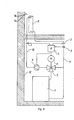
- In Fig. 6 ist das Ausführungsbeispiel einer Heizungsanlage zur Durchführung des erfindungsgemäßen Verfahrens dargestellt. Im Heizkreis befinden sich der
Vorlauftemperaturfühler 1, derRücklauftemperaturfühler 2 sowie derMengenstromfühler 3. Sie sind mittels Übertragungsleitungen mit dem Rechner 4 verbunden. Weitere Übertragungsleitungen führen vom Rechner 4 zummotorischen Stellglied 6 desMischventils 5 sowie zur Umwälzpumpe 9. Die Vorlaufleitung ist mit 10, die Rücklaufleitung von derHeizfläche 8 mit 11 bezeichnet.
- Fig. 1 shows the sequence of the method in a plant with a constant circulation flow. In a three-dimensional coordinate system with the axis values for the temperatures of the working medium t H and the outside air t a as well as for the circulation flow rate m, a system-specific characteristic
curve block K 1 is drawn. The block of characteristics is formed by the sum of all load level fields in a system. A load step field is the product of the difference between a flow temperature t V and the return temperature t R assigned to it with the assigned circulation flow rate m according to the formula (t V - t R ) × m. The load step fields L 1ʹ or L 2ʹ shown in the nomogram as cross-sectional areas, which are not integrated in the three-dimensional characteristic curve block K, correspond to the heat losses currently measured. They are moved within the characteristic block by a computer R (Fig. 6) until they coincide with the same-sized, precisely fitted loadlevel fields L 1 andL 2 in the characteristic block. The adjusted load levels The flow temperatures t V1 and t V2 assigned to the fields are the values searched for. - Fig. 2 shows the process flow in a plant in which individual parts of the plant are switched off and the circulating flow is reduced accordingly. The process is essentially the same as shown in Fig. 1, only the size of the respective load step area is reduced by a factor which corresponds to the reduction in the circulating flow, for example from m₄ to m₁.
- Fig. 3 shows in principle the same process as in Fig. 1, but from the aspect of a throttled, but unregulated circulation flow, as occurs, for example, in heating systems with thermostatic radiator valves, but whose temperature-related closing occurs with the circulating pump running at full capacity. Here a non-integrated load level field is shifted until its product of the difference between the flow and return temperature and the circulating flow is equal to the corresponding product of an integrated area level field.
- Fig. 4 shows the application of the method in a system with a step-by-step circulating flow. The total block of characteristics breaks down according to the number of flow control stages into several individual blocks K₁, K₂, K₃, K₄. Within a single block, e.g. B. K₂, a non-integrated load field L 2ʹ is moved to L₂ in the same way as shown in Fig. 1. However, the boundary between two individual blocks, e.g. B from K₃ to K₄, are skipped, then the product (t V - t R ) × m of the load step field L₃, first divided by the value m of the new single block K₄. The newly created, non-integrated load level field L dabei is shifted in the new single block K₄ until until it coincides with an integrated load level field L₄.
- 5 shows a further variant of the same basic principle, but with a continuously regulated circulation flow. It is characterized by a certain linear or non-linear decrease in the areas of the individual integrated load level fields in the area between full load and plant standstill. Here, too, a non-integrated load step field is shifted within a block of characteristics until its product of the difference between the flow and return temperature and the circulating flow is equal to the product of a load step field of the same area but integrated.
- 6 shows the exemplary embodiment of a heating system for carrying out the method according to the invention. The
flow temperature sensor 1, thereturn temperature sensor 2 and thevolume flow sensor 3 are located in the heating circuit. They are connected to the computer 4 by means of transmission lines. Further transmission lines lead from the computer 4 to themotorized actuator 6 of the mixingvalve 5 and to the circulation pump 9. The feed line is designated by 10, the return line from theheating surface 8 by 11.
Die Wirkungsweise der Anlage nach Fig. 6 ist folgende: Es sei angenommen, die Heizungsanlage habe sich auf eine Außentemperatur ta1 eines milden Wintertages einreguliert. Das Temperaturgefälle von ti nach ta1 ist gering, desgleichen auch die Wärmeabgabe der Heizfläche 8. Das Produkt aus der Differenz zwischen Vorlauf- und Rücklauftemperatur multipliziert mit dem Umwälzmengenstrom entspricht einem integrierten Laststufenfeld innerhalb des Kennlinienblocks der Anlage. Tritt nun ein Temperatursturz ein von ta1 nach ta2ʹ, dann wird zunächst die im Mauerwerk 12 gespeicherte Wärme schichtweise von außen her aufgezehrt, wie dies in Fig. 7 vereinfacht dargestellt ist. Dies ist ein allmählich fortschreitender Vorgang, bei welchem jedoch die Wärmeabgabe der Heizfläche 8 in gleichem Maße zunimmt, erkennbar am Absinken der Rücklauftemperatur. Die nunmehr eingetretene Laststufe kann der vorgegebenen Vorlauftemperatur nicht mehr zugeordnet werden. Der Rechner 4 errechnet nun an Hand der neuen Meßwerte der Fühler 1, 2 und 3 das neue, größere Laststufenfeld und verschiebt dieses innerhalb des gespeicherten Kennlinienblocks der Anlage soweit in Richtung auf eine höhere Vorlauftemperatur, bis es sich wieder voll integrieren läßt. Der hierbei selbsttätig aufgefundene, dem neuen Laststufenfeld zugeordnete Sollwert für die Vorlauftemperatur wird mit dem vom Fühler 1 gemessenen Istwert verglichen. Bei Abweichung errechnet der Rechner 4 ein Stellsignal, welches das Mischventil 5 über das motorische Stellglied 6 solange verstellt, bis die Vorlauftemperatur dem neuen Sollwert entspricht. Bei Anlagen mit Umwälzmengenregulierung erhält auch die Umwälzpumpe 9 vom Rechner 4 ein Signal zur Leistungsanpassung, die anhand der Meßwerte des Mengenstromfühlers 3 überwacht wird.The operation of the system according to FIG. 6 is as follows: It is assumed that the heating system has adjusted itself to an outside temperature t a1 on a mild winter day. The temperature gradient from t i to t a1 is small, as is the heat dissipation from
Steigt die Außentemperatur wieder an, beispielsweise von ta2 nach ta1 (Fig. 8), dann benötigt die schichtweise Erwärmung des Mauerwerks ebenfalls eine bestimmte Zeit. In dieser Zeit vermindert sich aber auch allmählich die Wärmeabgabe der Heizflächen 8, erkennbar am entsprechenden Ansteigen der Rücklauftemperatur. Das Laststufenfeld wird kleiner und kann in Richtung auf eine niedrigere Vorlauftemperatur verschoben werden, die sich dann bei der völligen Integration des neuen Laststufenfeldes im Kennlinienblock der Anlaqe als neuer Sollwert ergibt. Dementsprechend werden dann auch das Mischventil 5 und die Umwälzpumpe 9 gesteuert.If the outside temperature rises again, for example from t a2 to t a1 (FIG. 8), then the layered heating of the masonry also takes a certain time. During this time, however, the heat output of the heating surfaces 8 also gradually decreases, as can be seen from the corresponding rise in the return temperature. The load level field becomes smaller and can be shifted in the direction of a lower flow temperature, which then results as a new setpoint when the new load level field is fully integrated in the characteristic block of the system. The mixing
Der Verfahrensablauf ist auch dann prinzipiell der gleiche, wenn sich die Raumtemperatur zusätzlich durch innere Lasten ändert. Ein Absinken der Raumtemperatur, z. B. durch Lüften, vergrößert die Temperaturdifferenz zwischen Vorlauf und Rücklauf und somit auch das Laststufenfeld, welches nun in Richtung auf eine höhere Vorlauftemperatur verschoben wird. Umgekehrt führt eine Erwärmung der Raumluft, z B. durch eine größere Anzahl von Personen oder durch Abwärme von nicht heiztechnischen Einrichtungen zu einer Verringerung der Temperaturspreizung zwischen Vorlauf und Rücklauf und damit zu einer Verschiebung des Laststufenfeldes in Richtung auf eine niedrigere Vorlauftemperatur.The procedure is then basically the same, if the room temperature also changes due to internal loads. A decrease in the room temperature, e.g. B. by ventilation, increases the temperature difference between flow and return and thus also the load level field, which is now shifted in the direction of a higher flow temperature. Conversely, a warming of the room air, e.g. by a larger number of people or by waste heat from non-heating devices, leads to a reduction in the temperature spread between flow and return and thus to a shift in the load level field in the direction of a lower flow temperature.
Bei Anlagen, die ohne Mischventil betrieben werden können, steuert der Rechner 4 den Wärmeerzeuger auf direktem Wege. Desweiteren berücksichtigt der Rechner 4 beim Betrieb mit anderen Medien als Wasser deren abweichende spezifische Wärme. Im übrigen ist leicht erkennbar, daß die Erfindung nicht nur für die Raumlufttemperierung, sondern auch für industrielle Wärmeverbraucher, für verfahrenstechnische Zwecke und dergleichen geeignet ist, d. h. für Heizungsanlagen im weitesten Sinne. Auch eine Umkehrung des Verfahrens für Kühl- und Klimaanlagen ist ohne weiteres realisierbar.In systems that can be operated without a mixing valve, the computer 4 controls the heat generator directly. Furthermore, the computer 4 takes into account their different specific heat when operating with media other than water. Moreover, it is easy to see that the invention is not only suitable for room air temperature control, but also for industrial heat consumers, for process engineering purposes and the like, i. H. for heating systems in the broadest sense. The process for cooling and air conditioning systems can also be easily reversed.
Claims (11)
Priority Applications (1)
| Application Number | Priority Date | Filing Date | Title |
|---|---|---|---|
| AT88103684T ATE82630T1 (en) | 1987-03-19 | 1988-03-09 | METHOD OF CONTROLLING THE DELIVERY TEMPERATURE OF A HEAT TRANSMISSION SYSTEM. |
Applications Claiming Priority (2)
| Application Number | Priority Date | Filing Date | Title |
|---|---|---|---|
| DE3709085 | 1987-03-19 | ||
| DE19873709085 DE3709085A1 (en) | 1987-03-19 | 1987-03-19 | METHOD FOR CONTROLLING THE FLOW TEMPERATURE OF A HEATING SYSTEM |
Publications (3)
| Publication Number | Publication Date |
|---|---|
| EP0282886A2 true EP0282886A2 (en) | 1988-09-21 |
| EP0282886A3 EP0282886A3 (en) | 1988-11-30 |
| EP0282886B1 EP0282886B1 (en) | 1992-11-19 |
Family
ID=6323538
Family Applications (1)
| Application Number | Title | Priority Date | Filing Date |
|---|---|---|---|
| EP88103684A Expired - Lifetime EP0282886B1 (en) | 1987-03-19 | 1988-03-09 | Process for regulating the start temperature in a heat transfer system |
Country Status (8)
| Country | Link |
|---|---|
| US (1) | US4884743A (en) |
| EP (1) | EP0282886B1 (en) |
| JP (1) | JPH01119811A (en) |
| CN (1) | CN1013065B (en) |
| AT (1) | ATE82630T1 (en) |
| DE (2) | DE3709085A1 (en) |
| DK (1) | DK150388A (en) |
| FI (1) | FI881313A (en) |
Cited By (8)
| Publication number | Priority date | Publication date | Assignee | Title |
|---|---|---|---|---|
| EP0624760A1 (en) * | 1993-05-11 | 1994-11-17 | Georg Lachenmeier | Method for controlling the pump of a heating installation |
| EP1191287A2 (en) | 2000-09-20 | 2002-03-27 | KSB Aktiengesellschaft | Pipe system for thermal energy exchange |
| EP1645928A1 (en) * | 2004-10-07 | 2006-04-12 | Techem Energy Services GmbH | Method of determining the supply state of a heating surface and supply state regulator |
| WO2013078570A1 (en) | 2011-11-28 | 2013-06-06 | Belimo Holding Ag | Method for regulating the room temperature in a room or in a group comprising multiple rooms, and apparatus for carrying out the method |
| EP2913594A1 (en) * | 2014-02-28 | 2015-09-02 | Robert Bosch Gmbh | Method for operating a heating system with no buffer storage, in particular for guaranteeing safe and correct operation |
| EP2498010A3 (en) * | 2011-03-11 | 2016-05-18 | Gebr. Tuxhorn GmbH & Co. KG | Method for return temperature raising and device for return temperature raising |
| EP3889511A1 (en) * | 2020-03-25 | 2021-10-06 | Robert Bosch GmbH | Heating system and method for controlling a heating circuit of a heating system, control unit for a heating system |
| EP4332445A1 (en) * | 2022-08-31 | 2024-03-06 | Danfoss A/S | Method for controlling a temperature influencing system and temperature influencing system |
Families Citing this family (15)
| Publication number | Priority date | Publication date | Assignee | Title |
|---|---|---|---|---|
| DE4219653C1 (en) * | 1992-06-16 | 1993-10-21 | Dieter Dipl Ing Bohn | Process for temperature control using heating systems |
| DE4312150C2 (en) * | 1993-04-14 | 1998-12-24 | Ewald Hennel | Method for adjusting the delivery rate of a circulation pump |
| US5501265A (en) * | 1994-05-31 | 1996-03-26 | Carrier Corporation | Fluid flow control for HVAC system with valve position readjustment to equalize conditioning rates in multiple zones |
| JP4582511B2 (en) * | 1998-07-17 | 2010-11-17 | 株式会社フジキン | Design apparatus and design method for fluid control device |
| US7925389B2 (en) * | 2006-06-15 | 2011-04-12 | International Business Machines Corporation | Method of detecting recirculation of heated air within a rack enclosure |
| DE102008054043A1 (en) | 2008-10-30 | 2010-05-12 | Techem Energy Services Gmbh | Method and device for heat demand-guided adaptation of the flow temperature of a heating system |
| KR100929210B1 (en) * | 2009-04-29 | 2009-12-01 | 주식회사 삼양발부종합메이커 | Apparatus for automatic control of constant flow |
| DE102012101625A1 (en) * | 2012-02-28 | 2013-08-29 | Kermi Gmbh | heating control |
| US20160230767A1 (en) * | 2015-02-11 | 2016-08-11 | Steve Thompson | High efficiency hydronic circulator with sensors |
| SE542257C2 (en) * | 2016-09-26 | 2020-03-24 | Clean Bio Heat Sverige Ab | Flue gas treatment system and method |
| CN108338414B (en) * | 2017-01-25 | 2022-05-27 | 贵州中烟工业有限责任公司 | Control method and control system of electric heating smoking system |
| CN108338416B (en) * | 2017-01-25 | 2022-05-31 | 贵州中烟工业有限责任公司 | Inner core type heating smoking system |
| CN108338417B (en) * | 2017-01-25 | 2022-05-27 | 贵州中烟工业有限责任公司 | Electric heating smoking system based on micro-heater |
| CN108338415B (en) * | 2017-01-25 | 2022-05-31 | 贵州中烟工业有限责任公司 | Peripheral heating smoking system |
| CN113124572B (en) * | 2021-03-30 | 2022-07-19 | 青岛海尔空调器有限总公司 | Fan heater control method, fan heater and storage medium |
Citations (3)
| Publication number | Priority date | Publication date | Assignee | Title |
|---|---|---|---|---|
| DE2811153A1 (en) * | 1978-03-15 | 1979-09-20 | Wolfgang Behm | Automatic room heating control system - uses supply and return flow temps. under stationary conditions to establish flow temp. and control circuit |
| US4497438A (en) * | 1982-12-23 | 1985-02-05 | Honeywell Inc. | Adaptive, modulating boiler control system |
| EP0195255A2 (en) * | 1985-02-18 | 1986-09-24 | HAPPEL GmbH & Co. | Method and apparatus for space temperature regulation |
Family Cites Families (12)
| Publication number | Priority date | Publication date | Assignee | Title |
|---|---|---|---|---|
| US2893634A (en) * | 1956-11-15 | 1959-07-07 | Bailey Meter Co | Three dimensional calculator |
| US3979710A (en) * | 1970-11-16 | 1976-09-07 | Danfoss A/S | Apparatus for adjusting and indicating the operating curve of a weather-responsive heating regulator |
| DE2731922A1 (en) * | 1977-05-06 | 1978-11-09 | Elesta Ag Elektronik | PROTECTIVE CIRCUIT AGAINST LOW TEMPERATURE CORROSION OF THE BOILER |
| DE2747969A1 (en) * | 1977-10-26 | 1979-05-10 | Braukmann Armaturen | CONTROL DEVICE FOR A HEATING SYSTEM |
| DE3036121A1 (en) * | 1980-09-25 | 1982-05-06 | Heinrich Ing.(grad.) 4000 Düsseldorf Brockerhoff | Central-heating operating system - has charge temperature following predetermined curve and pump delivering reduced quantity above freezing |
| US4437164A (en) * | 1981-03-05 | 1984-03-13 | Bristol Babcock Inc. | Ridge circuit compensation for environmental effects |
| DE3203832A1 (en) * | 1982-02-04 | 1983-08-18 | Centra-Bürkle GmbH & Co, 7036 Schönaich | Method and regulating device for regulating a heating circuit |
| CH666129A5 (en) * | 1984-01-13 | 1988-06-30 | Jakob Huber | METHOD FOR CONTROLLING A THERMAL SYSTEM. |
| DE3404091A1 (en) * | 1984-02-07 | 1985-08-08 | Stiebel Eltron Gmbh & Co Kg, 3450 Holzminden | Control device for a heating plant |
| SE457671B (en) * | 1984-02-17 | 1989-01-16 | Lampert Heinz | DEVICE FOR Saturation of the amount of heat emitted to a room and the regulation of room temperature |
| DE3568859D1 (en) * | 1984-12-24 | 1989-04-20 | Tno | Apparatus and method for adjusting a central heating installation |
| DE3544905A1 (en) * | 1985-12-19 | 1987-06-25 | Rhein Westfael Elect Werk Ag | METHOD FOR CONTROLLING A BIVALENT HEATING DEVICE |
-
1987
- 1987-03-19 DE DE19873709085 patent/DE3709085A1/en not_active Withdrawn
-
1988
- 1988-03-09 AT AT88103684T patent/ATE82630T1/en not_active IP Right Cessation
- 1988-03-09 DE DE8888103684T patent/DE3875988D1/en not_active Expired - Lifetime
- 1988-03-09 EP EP88103684A patent/EP0282886B1/en not_active Expired - Lifetime
- 1988-03-18 FI FI881313A patent/FI881313A/en not_active IP Right Cessation
- 1988-03-18 JP JP63063784A patent/JPH01119811A/en active Pending
- 1988-03-18 DK DK150388A patent/DK150388A/en not_active IP Right Cessation
- 1988-03-19 CN CN88102154A patent/CN1013065B/en not_active Expired
- 1988-03-21 US US07/171,479 patent/US4884743A/en not_active Expired - Fee Related
Patent Citations (3)
| Publication number | Priority date | Publication date | Assignee | Title |
|---|---|---|---|---|
| DE2811153A1 (en) * | 1978-03-15 | 1979-09-20 | Wolfgang Behm | Automatic room heating control system - uses supply and return flow temps. under stationary conditions to establish flow temp. and control circuit |
| US4497438A (en) * | 1982-12-23 | 1985-02-05 | Honeywell Inc. | Adaptive, modulating boiler control system |
| EP0195255A2 (en) * | 1985-02-18 | 1986-09-24 | HAPPEL GmbH & Co. | Method and apparatus for space temperature regulation |
Cited By (10)
| Publication number | Priority date | Publication date | Assignee | Title |
|---|---|---|---|---|
| EP0624760A1 (en) * | 1993-05-11 | 1994-11-17 | Georg Lachenmeier | Method for controlling the pump of a heating installation |
| EP1191287A2 (en) | 2000-09-20 | 2002-03-27 | KSB Aktiengesellschaft | Pipe system for thermal energy exchange |
| DE10046862A1 (en) * | 2000-09-20 | 2002-03-28 | Ksb Ag | Pipe system for thermal energy transfer |
| EP1645928A1 (en) * | 2004-10-07 | 2006-04-12 | Techem Energy Services GmbH | Method of determining the supply state of a heating surface and supply state regulator |
| EP1933220A3 (en) * | 2004-10-07 | 2010-02-17 | Techem Energy Services GmbH | Method of determining the supply state of a heating surface and supply state regulator |
| EP2498010A3 (en) * | 2011-03-11 | 2016-05-18 | Gebr. Tuxhorn GmbH & Co. KG | Method for return temperature raising and device for return temperature raising |
| WO2013078570A1 (en) | 2011-11-28 | 2013-06-06 | Belimo Holding Ag | Method for regulating the room temperature in a room or in a group comprising multiple rooms, and apparatus for carrying out the method |
| EP2913594A1 (en) * | 2014-02-28 | 2015-09-02 | Robert Bosch Gmbh | Method for operating a heating system with no buffer storage, in particular for guaranteeing safe and correct operation |
| EP3889511A1 (en) * | 2020-03-25 | 2021-10-06 | Robert Bosch GmbH | Heating system and method for controlling a heating circuit of a heating system, control unit for a heating system |
| EP4332445A1 (en) * | 2022-08-31 | 2024-03-06 | Danfoss A/S | Method for controlling a temperature influencing system and temperature influencing system |
Also Published As
| Publication number | Publication date |
|---|---|
| EP0282886A3 (en) | 1988-11-30 |
| DE3875988D1 (en) | 1992-12-24 |
| FI881313A0 (en) | 1988-03-18 |
| CN1013065B (en) | 1991-07-03 |
| CN88102154A (en) | 1988-12-21 |
| DE3709085A1 (en) | 1988-09-29 |
| ATE82630T1 (en) | 1992-12-15 |
| DK150388A (en) | 1988-09-20 |
| DK150388D0 (en) | 1988-03-18 |
| US4884743A (en) | 1989-12-05 |
| FI881313A (en) | 1988-09-20 |
| JPH01119811A (en) | 1989-05-11 |
| EP0282886B1 (en) | 1992-11-19 |
Similar Documents
| Publication | Publication Date | Title |
|---|---|---|
| EP0282886B1 (en) | Process for regulating the start temperature in a heat transfer system | |
| DE3116521C2 (en) | ||
| DE3246838C2 (en) | ||
| DE2714511C2 (en) | Device for regulating the flow temperature in a collective heating system | |
| EP3722680B1 (en) | Method for carrying out a hydraulic adjustment of a heating system for a building and heating system designed for this purpose | |
| EP2965161B1 (en) | Method and system for the temperature control of components | |
| EP2913594A1 (en) | Method for operating a heating system with no buffer storage, in particular for guaranteeing safe and correct operation | |
| EP2636959B1 (en) | Heater control | |
| EP2095028B1 (en) | Temperature regulation system, and method for cooling-mode and heating-mode operation of such a temperature regulation system | |
| EP3101352A1 (en) | Method for operating a heating installation and controller with differential pressure sensor | |
| DE2908355A1 (en) | Tempering recirculated heat transfer medium - by providing inlet and outlet of recirculating circuit with by=pass for mixing medium with tempered medium | |
| DE3030565A1 (en) | Boiler for domestic heating systems - has burner connected to and regulated by room temp. control using three=way valve | |
| EP0643271B1 (en) | Process for controlling the temperature and the humidity of the air in rooms with an air conditioning installation | |
| DE2529858C2 (en) | Method and device for regulating a heat transfer system | |
| DE102010056301A1 (en) | Method for automatic optimizing heat-up phase of heating system comprising heat generator for heating room, involves simulating actual and proximate target room temperature | |
| EP0352401B1 (en) | Process for regulating the amount of heat carried to the consumers of a heating system and control unit. | |
| DE3408622A1 (en) | Heating plate for a press | |
| EP2655979B1 (en) | Method for controlling a heat generator of a heating system, and heating system | |
| DE102010053209A1 (en) | Heating system and method for heating a plurality of rooms | |
| EP3816531B1 (en) | Method for adjusting the operating state of a circuit composite system of an air technical, preferably space-air technical installation | |
| DE2524302A1 (en) | Building central heating plant - includes automatic preset regulating valve in flow line | |
| EP2638447B1 (en) | Device for adjusting an individual operating temperature of machine elements of a machine tool | |
| EP0103859B1 (en) | Control process for the temperature of the forward or backward flow of a heating plant, fed by a heat source | |
| DE2712110A1 (en) | Combined system for heating and cooling - has refrigerating circuit with auxiliary condenser which is loaded at predetermined refrigerant pressure | |
| EP0711960A1 (en) | Method and device for heating water for domestic use |
Legal Events
| Date | Code | Title | Description |
|---|---|---|---|
| PUAI | Public reference made under article 153(3) epc to a published international application that has entered the european phase |
Free format text: ORIGINAL CODE: 0009012 |
|
| AK | Designated contracting states |
Kind code of ref document: A2 Designated state(s): AT BE CH DE FR GB IT LI NL SE |
|
| PUAL | Search report despatched |
Free format text: ORIGINAL CODE: 0009013 |
|
| AK | Designated contracting states |
Kind code of ref document: A3 Designated state(s): AT BE CH DE FR GB IT LI NL SE |
|
| 17P | Request for examination filed |
Effective date: 19881102 |
|
| 17Q | First examination report despatched |
Effective date: 19900312 |
|
| 111Z | Information provided on other rights and legal means of execution |
Free format text: AT BE CH DE FR GB IT LI NL SE |
|
| GRAA | (expected) grant |
Free format text: ORIGINAL CODE: 0009210 |
|
| AK | Designated contracting states |
Kind code of ref document: B1 Designated state(s): AT BE CH DE FR GB IT LI NL SE |
|
| PG25 | Lapsed in a contracting state [announced via postgrant information from national office to epo] |
Ref country code: IT Free format text: LAPSE BECAUSE OF FAILURE TO SUBMIT A TRANSLATION OF THE DESCRIPTION OR TO PAY THE FEE WITHIN THE PRE;WARNING: LAPSES OF ITALIAN PATENTS WITH EFFECTIVE DATE BEFORE 2007 MAY HAVE OCCURRED AT ANY TIME BEFORE 2007. THE CORRECT EFFECTIVE DATE MAY BE DIFFERENT FROM THE ONE RECORDED.SCRIBED TIME-LIMIT Effective date: 19921119 Ref country code: NL Effective date: 19921119 Ref country code: FR Effective date: 19921119 Ref country code: GB Effective date: 19921119 Ref country code: SE Effective date: 19921119 Ref country code: BE Effective date: 19921119 |
|
| REF | Corresponds to: |
Ref document number: 82630 Country of ref document: AT Date of ref document: 19921215 Kind code of ref document: T |
|
| REF | Corresponds to: |
Ref document number: 3875988 Country of ref document: DE Date of ref document: 19921224 |
|
| PG25 | Lapsed in a contracting state [announced via postgrant information from national office to epo] |
Ref country code: AT Effective date: 19930309 |
|
| PG25 | Lapsed in a contracting state [announced via postgrant information from national office to epo] |
Ref country code: LI Effective date: 19930331 Ref country code: CH Effective date: 19930331 |
|
| EN | Fr: translation not filed | ||
| NLV1 | Nl: lapsed or annulled due to failure to fulfill the requirements of art. 29p and 29m of the patents act | ||
| GBV | Gb: ep patent (uk) treated as always having been void in accordance with gb section 77(7)/1977 [no translation filed] |
Effective date: 19921119 |
|
| PLBE | No opposition filed within time limit |
Free format text: ORIGINAL CODE: 0009261 |
|
| STAA | Information on the status of an ep patent application or granted ep patent |
Free format text: STATUS: NO OPPOSITION FILED WITHIN TIME LIMIT |
|
| 26N | No opposition filed | ||
| REG | Reference to a national code |
Ref country code: CH Ref legal event code: PL |
|
| PG25 | Lapsed in a contracting state [announced via postgrant information from national office to epo] |
Ref country code: DE Free format text: LAPSE BECAUSE OF NON-PAYMENT OF DUE FEES Effective date: 19940331 |
|
| PGFP | Annual fee paid to national office [announced via postgrant information from national office to epo] |
Ref country code: DE Payment date: 19990412 Year of fee payment: 12 |