EP0282868B1 - Steuerschieber mit Hebelbetätigung - Google Patents
Steuerschieber mit Hebelbetätigung Download PDFInfo
- Publication number
- EP0282868B1 EP0282868B1 EP88103533A EP88103533A EP0282868B1 EP 0282868 B1 EP0282868 B1 EP 0282868B1 EP 88103533 A EP88103533 A EP 88103533A EP 88103533 A EP88103533 A EP 88103533A EP 0282868 B1 EP0282868 B1 EP 0282868B1
- Authority
- EP
- European Patent Office
- Prior art keywords
- spool
- coupling member
- valve according
- spool valve
- lever
- Prior art date
- Legal status (The legal status is an assumption and is not a legal conclusion. Google has not performed a legal analysis and makes no representation as to the accuracy of the status listed.)
- Expired - Lifetime
Links
- 230000008878 coupling Effects 0.000 claims abstract description 52
- 238000010168 coupling process Methods 0.000 claims abstract description 52
- 238000005859 coupling reaction Methods 0.000 claims abstract description 52
- 230000033001 locomotion Effects 0.000 claims abstract description 22
- 230000005540 biological transmission Effects 0.000 claims description 4
- 210000004907 gland Anatomy 0.000 description 2
- 230000001771 impaired effect Effects 0.000 description 2
- 238000004519 manufacturing process Methods 0.000 description 2
- 238000005452 bending Methods 0.000 description 1
- 238000007789 sealing Methods 0.000 description 1
Images

Classifications
-
- F—MECHANICAL ENGINEERING; LIGHTING; HEATING; WEAPONS; BLASTING
- F16—ENGINEERING ELEMENTS AND UNITS; GENERAL MEASURES FOR PRODUCING AND MAINTAINING EFFECTIVE FUNCTIONING OF MACHINES OR INSTALLATIONS; THERMAL INSULATION IN GENERAL
- F16K—VALVES; TAPS; COCKS; ACTUATING-FLOATS; DEVICES FOR VENTING OR AERATING
- F16K27/00—Construction of housing; Use of materials therefor
- F16K27/02—Construction of housing; Use of materials therefor of lift valves
-
- F—MECHANICAL ENGINEERING; LIGHTING; HEATING; WEAPONS; BLASTING
- F16—ENGINEERING ELEMENTS AND UNITS; GENERAL MEASURES FOR PRODUCING AND MAINTAINING EFFECTIVE FUNCTIONING OF MACHINES OR INSTALLATIONS; THERMAL INSULATION IN GENERAL
- F16K—VALVES; TAPS; COCKS; ACTUATING-FLOATS; DEVICES FOR VENTING OR AERATING
- F16K31/00—Actuating devices; Operating means; Releasing devices
- F16K31/44—Mechanical actuating means
Definitions
- the invention relates to a spool of the type specified in the preamble of claim 1.
- the coupling member is screwed into the slide piston with an axial stop, in such a way that the interlocking threads are supported on one another with their flanks in the axial direction.
- the coupling member forms a rigid extension of the slide piston, so to speak.
- the movement components of the articulation point between the coupling member and the actuating lever, which are directed around the longitudinal axis of the spool piston, are eliminated in the compensation device, which consists of a longitudinal slot in the actuating lever, in which a pivot pin of the coupling member is slidably supported.
- the attachment of the longitudinal slot means an additional effort in the manufacture of the actuating lever.
- the adjustment accuracy is impaired because the longitudinal slot allows the pivot pin to make slight transverse movements, by means of which the lever movement is only transmitted inexactly to the slide piston.
- the coupling member is via a cross pin pivotally connected to the slide piston, which forms the compensation device for the transverse components.
- the pivot connection between the coupling member and the spool is relatively complex to manufacture and difficult to assemble.
- valve element In a valve for high pressure known from US-A-201 47 59, the valve element is designed as an elongated hollow piston which protrudes from the valve housing and is connected to an L-shaped coupling member which is screwed into a continuous threaded bore in the piston crown with an external thread is.
- the piston passes through a gland and an elongated gland sleeve, which also acts as a guide for the piston.
- the coupling member is anchored outside the valve housing.
- the coupling member is connected to the actuating lever via a pivot pin.
- the actuating lever is in turn mounted in a yoke that can be pivoted on the valve housing.
- Movement components of the articulation point between the coupling member and the actuating lever directed transversely to the longitudinal axis of the piston are compensated for in that the articulation area of the actuating lever on the yoke is pivoted about the yoke pivot axis on the valve housing.
- the invention has for its object to provide a control valve of the type mentioned with a structurally and assembly technically simple compensation device.
- claim 2 is important because the threaded connection is not tightened to a fixed stop, but because of the lack of an axial stop, a desired slight play between the threads is guaranteed.
- the coupling member has the pivoting movement sufficient to compensate for the arc movement of the articulation point.
- the slide piston has a recess at one end, in which the screw-in point of the coupling member lies inside the slide piston.
- a particularly low load with low wear of the seal is achieved in the embodiment according to claim 5.
- the seal is set so far towards the screw-in point that the external thread no longer enters the seal and damages it.
- the coupling member is slightly inclined in the middle position of the actuating lever.
- the coupling member in the middle position of the actuating lever were aligned precisely with the longitudinal axis of the slide piston, it would be deflected relatively far out of the middle position in the two end positions of the slide piston, which in some circumstances would mean an unusually high and one-sided load for the seal.
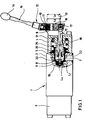
- a control slide 1 according to FIG. 1 has a block-shaped housing 2 with end caps 3 and 4 as well as a continuous slide bore 5 for a slide piston 6 which can be moved back and forth in a straight line.
- the slide piston is moved by springs 25 in one Held in the middle position.
- the springs are also responsible for securing the slide piston 6 against rotation.
- An open recess 7 is formed in one end of the slide piston 6, which opens access to a threaded bore 8.
- a bearing block 9 for a pivot bearing 10 is fastened to the end cap 4, the axis of which is designated 11 is laterally offset by a distance L3 from the longitudinal axis 12 of the slide piston.
- a two-armed manual control lever 12 is pivotally mounted, one arm 15 of which carries a handle 14 at the free end.
- the other, designated 16 arm of the actuating lever 12 is pivotally connected in an articulation point 17 to one end of a pin-shaped coupling member 18.
- the coupling member 18 protrudes into the recess 7 of the slide piston 6 and is anchored at its end 19 in the slide piston 6.
- the end 19 carries an external thread 20 which is screwed into the threaded bore 8 of the slide piston 6.
- the threaded bore 8 has a greater thread depth L1 than the screw-in depth L4 of the external thread 20, so that it is not tightened against the stop.
- the distance L2 between the axis 11 of the pivot bearing 10 and the articulation point 17 is greater than the distance L3 between the axis 11 and the longitudinal axis 12, so that the longitudinal axis 13 of the coupling member 18 in the illustrated central position of the slide piston 6 with the longitudinal axis 12 is a small one Includes angle.
- the end cap 4 has a protruding collar 26 which surrounds the coupling member 18 with lateral play and projects into the recess 7 of the slide piston 6 with lateral play.
- the inner wall of the collar 26 is designated 21.
- a seal 22 is held in which the coupling member 18 is guided in a sliding fit.
- Fig. 2 is enlarged and can be seen in detail that between the inner wall 21 of the collar 26 and the coupling member 18 in the zero position 0 designated with the actuating lever 12 there is a greater distance S1 than S2 below, due to the deliberate inclination of the coupling member 28 with respect to the longitudinal axis of the slide piston 2.
- the screwing depth L4 of the external thread 20 into the threaded bore 8 of the slide piston 6 is approximately D to 1.5D, where D is the thread diameter.
- the slide piston 6 has a total stroke of 16 mm, ie a stroke of 8 mm from the zero position of the actuating lever 12.
- the actuating lever 12 swivels between the two end positions I and II by 16 ° to each side.
- the external thread 20 of the coupling member 18 is at least a distance of 8 mm from the seal 22, so that the external thread 20 cannot damage the seal 22.
- the articulation point 17 executes an arc movement up to the end points 17I and 17II, whereby it carries out a transverse stroke X in relation to its position in the zero position.
- the coupling member 18 is in the zero position so far inclined against the slide piston longitudinal axis 12 that the slide piston longitudinal axis 12 approximately halves the transverse stroke X. In this way, the load on the seal 22 is as uniform as possible.
- the coupling member 18 also performs a pivoting movement about a fictitious point 24, the seal 22 alternatingly in each case according to both Sides is charged.
- the distance S1 changes, ie it becomes smaller, while the distance S2 increases.
- the coupling member 18 can be removed from the slide piston 6 by simply unscrewing it, if, for example, pressure pilot control of the slide piston 6 is provided instead of actuating the lever. It is then only necessary to insert a sealing plug into the inner bore 23 of the collar 26. Since the threaded connection between the coupling member 18 and the spool 6 is not tightened to the stop, it is expedient to provide an anti-rotation device for the spool 6. In the present embodiment, the springs 25 take over this anti-rotation. Alternatively, however, other anti-rotation devices, e.g. positive anti-rotation locks may be provided. It is furthermore expedient to make the coupling member 18 as slim as possible in its area passing through the seal 22 in order to increase the bending elasticity of the coupling member 18. However, the coupling member 18 may only be so slim that it still has sufficient buckling rigidity.
Landscapes
- Engineering & Computer Science (AREA)
- General Engineering & Computer Science (AREA)
- Mechanical Engineering (AREA)
- Mechanically-Actuated Valves (AREA)
Priority Applications (1)
| Application Number | Priority Date | Filing Date | Title |
|---|---|---|---|
| AT88103533T ATE77456T1 (de) | 1987-03-20 | 1988-03-07 | Steuerschieber mit hebelbetaetigung. |
Applications Claiming Priority (2)
| Application Number | Priority Date | Filing Date | Title |
|---|---|---|---|
| DE19873709151 DE3709151A1 (de) | 1987-03-20 | 1987-03-20 | Steuerschieber mit hebelbetaetigung |
| DE3709151 | 1987-03-20 |
Publications (3)
| Publication Number | Publication Date |
|---|---|
| EP0282868A2 EP0282868A2 (de) | 1988-09-21 |
| EP0282868A3 EP0282868A3 (en) | 1989-07-26 |
| EP0282868B1 true EP0282868B1 (de) | 1992-06-17 |
Family
ID=6323570
Family Applications (1)
| Application Number | Title | Priority Date | Filing Date |
|---|---|---|---|
| EP88103533A Expired - Lifetime EP0282868B1 (de) | 1987-03-20 | 1988-03-07 | Steuerschieber mit Hebelbetätigung |
Country Status (3)
| Country | Link |
|---|---|
| EP (1) | EP0282868B1 (https=) |
| AT (1) | ATE77456T1 (https=) |
| DE (2) | DE3709151A1 (https=) |
Families Citing this family (2)
| Publication number | Priority date | Publication date | Assignee | Title |
|---|---|---|---|---|
| DE4443178C1 (de) * | 1994-11-23 | 1996-03-28 | Mannesmann Ag | Direktgesteuertes Wegeschieberventil |
| CN121251830B (zh) * | 2025-12-04 | 2026-03-17 | 福建云联中汇环保科技有限公司 | 一种污水处理用防淤堵阀门 |
Family Cites Families (8)
| Publication number | Priority date | Publication date | Assignee | Title |
|---|---|---|---|---|
| DE1249042B (https=) * | 1967-08-31 | |||
| US1384670A (en) * | 1920-07-13 | 1921-07-12 | Arturo Munder Y Barrie | Faucet |
| US2014759A (en) * | 1935-01-16 | 1935-09-17 | Ollie C Clay | High pressure valve |
| US2347676A (en) * | 1943-03-10 | 1944-05-02 | Manning Maxwell & Moore Inc | Safety valve |
| FR968477A (fr) * | 1947-06-28 | 1950-11-28 | Perfectionnements à un ensemble de robinets | |
| US3656710A (en) * | 1970-07-09 | 1972-04-18 | Golconda Corp | Bottom opening valve |
| DE3000085A1 (de) * | 1980-01-03 | 1981-07-09 | Heilmeier & Weinlein Fabrik für Oel-Hydraulik GmbH & Co KG, 8000 München | Hebelbetaetigtes steuerventil |
| DE3208359A1 (de) * | 1982-03-09 | 1983-09-22 | Rötelmann & Co, 5980 Werdohl | Ventil zur steuerung hydraulischer systeme |
-
1987
- 1987-03-20 DE DE19873709151 patent/DE3709151A1/de active Granted
-
1988
- 1988-03-07 AT AT88103533T patent/ATE77456T1/de not_active IP Right Cessation
- 1988-03-07 DE DE8888103533T patent/DE3872004D1/de not_active Expired - Lifetime
- 1988-03-07 EP EP88103533A patent/EP0282868B1/de not_active Expired - Lifetime
Also Published As
| Publication number | Publication date |
|---|---|
| DE3872004D1 (de) | 1992-07-23 |
| DE3709151C2 (https=) | 1990-06-28 |
| ATE77456T1 (de) | 1992-07-15 |
| EP0282868A2 (de) | 1988-09-21 |
| EP0282868A3 (en) | 1989-07-26 |
| DE3709151A1 (de) | 1988-09-29 |
Similar Documents
| Publication | Publication Date | Title |
|---|---|---|
| EP0047826B1 (de) | In Offenstellung verrastbarer Türschliesser | |
| DE102013111456B4 (de) | Abschaltventil | |
| EP2334952A1 (de) | Spindeltrieb mit verdrehsicherung | |
| WO2001029432A2 (de) | Betätigungsvorrichtung für ein drehbares verschlussteil eines ventils | |
| DE69716849T2 (de) | Selbsteinstellendes endstück für bowdenzugkabel | |
| EP2320100B1 (de) | Zug-Druck-Stange | |
| DE2832801A1 (de) | Betaetigungseinrichtung fuer ein ventil | |
| EP0567787A1 (de) | Stellventil | |
| EP0282868B1 (de) | Steuerschieber mit Hebelbetätigung | |
| EP0622574A2 (de) | Betätigungsvorrichtung für ein drehbares Verschlussstück eines Ventils | |
| EP4621271A1 (de) | Adapter zum anschliessen eines antriebsmittels an einen manuell betätigbaren absperrhahn und system aus einem solchen adapter und einem manuell betätigbaren absperrhahn | |
| DE102020102081A1 (de) | Verbindungsvorrichtung zur Verbindung einer Ventilstange mit einem Verschlussglied eines Vakuumventils | |
| DE19845684C2 (de) | Stellungsregler für einen druckmittelbetriebenen Stellantrieb | |
| DD245292A5 (de) | Gelenkbolzen- oder -achsenfuehrung, insbesondere fuer ein musikinstrument | |
| DE19702251C2 (de) | Zentralverriegelungsstellelement für Türen oder Klappen von Kraftfahrzeugen | |
| DE2709228C2 (de) | Klappenstütze | |
| DE10044182A1 (de) | Stellglied | |
| DE69413797T2 (de) | Verschlussventil für eine selbsteinstellende hydraulische einrichtung | |
| DE3812285C2 (https=) | ||
| DE102012213220B4 (de) | Linearbewegungsvorrichtung | |
| DE3000086C2 (https=) | ||
| DE102008010135B4 (de) | Eckventil | |
| DE3135109C2 (de) | Ventil, insbesondere Steuer- oder Regelventil | |
| DE3000085C2 (https=) | ||
| DE3208359A1 (de) | Ventil zur steuerung hydraulischer systeme |
Legal Events
| Date | Code | Title | Description |
|---|---|---|---|
| PUAI | Public reference made under article 153(3) epc to a published international application that has entered the european phase |
Free format text: ORIGINAL CODE: 0009012 |
|
| AK | Designated contracting states |
Kind code of ref document: A2 Designated state(s): AT DE FR GB IT NL SE |
|
| PUAL | Search report despatched |
Free format text: ORIGINAL CODE: 0009013 |
|
| RHK1 | Main classification (correction) |
Ipc: F16K 1/48 |
|
| AK | Designated contracting states |
Kind code of ref document: A3 Designated state(s): AT DE FR GB IT NL SE |
|
| 17P | Request for examination filed |
Effective date: 19890829 |
|
| 17Q | First examination report despatched |
Effective date: 19901002 |
|
| RAP3 | Party data changed (applicant data changed or rights of an application transferred) |
Owner name: HEILMEIER & WEINLEIN FABRIK FUER OEL-HYDRAULIK GMB |
|
| GRAA | (expected) grant |
Free format text: ORIGINAL CODE: 0009210 |
|
| AK | Designated contracting states |
Kind code of ref document: B1 Designated state(s): AT DE FR GB IT NL SE |
|
| REF | Corresponds to: |
Ref document number: 77456 Country of ref document: AT Date of ref document: 19920715 Kind code of ref document: T |
|
| GBT | Gb: translation of ep patent filed (gb section 77(6)(a)/1977) | ||
| REF | Corresponds to: |
Ref document number: 3872004 Country of ref document: DE Date of ref document: 19920723 |
|
| ET | Fr: translation filed | ||
| ITF | It: translation for a ep patent filed | ||
| PLBE | No opposition filed within time limit |
Free format text: ORIGINAL CODE: 0009261 |
|
| STAA | Information on the status of an ep patent application or granted ep patent |
Free format text: STATUS: NO OPPOSITION FILED WITHIN TIME LIMIT |
|
| 26N | No opposition filed | ||
| EAL | Se: european patent in force in sweden |
Ref document number: 88103533.1 |
|
| PGFP | Annual fee paid to national office [announced via postgrant information from national office to epo] |
Ref country code: GB Payment date: 19980223 Year of fee payment: 11 |
|
| PGFP | Annual fee paid to national office [announced via postgrant information from national office to epo] |
Ref country code: AT Payment date: 19980226 Year of fee payment: 11 |
|
| PGFP | Annual fee paid to national office [announced via postgrant information from national office to epo] |
Ref country code: FR Payment date: 19980319 Year of fee payment: 11 |
|
| PGFP | Annual fee paid to national office [announced via postgrant information from national office to epo] |
Ref country code: SE Payment date: 19980325 Year of fee payment: 11 |
|
| PGFP | Annual fee paid to national office [announced via postgrant information from national office to epo] |
Ref country code: NL Payment date: 19980331 Year of fee payment: 11 |
|
| PG25 | Lapsed in a contracting state [announced via postgrant information from national office to epo] |
Ref country code: GB Free format text: LAPSE BECAUSE OF NON-PAYMENT OF DUE FEES Effective date: 19990307 Ref country code: AT Free format text: LAPSE BECAUSE OF NON-PAYMENT OF DUE FEES Effective date: 19990307 |
|
| PG25 | Lapsed in a contracting state [announced via postgrant information from national office to epo] |
Ref country code: SE Free format text: LAPSE BECAUSE OF NON-PAYMENT OF DUE FEES Effective date: 19990308 |
|
| PG25 | Lapsed in a contracting state [announced via postgrant information from national office to epo] |
Ref country code: NL Free format text: LAPSE BECAUSE OF NON-PAYMENT OF DUE FEES Effective date: 19991001 |
|
| GBPC | Gb: european patent ceased through non-payment of renewal fee |
Effective date: 19990307 |
|
| EUG | Se: european patent has lapsed |
Ref document number: 88103533.1 |
|
| PG25 | Lapsed in a contracting state [announced via postgrant information from national office to epo] |
Ref country code: FR Free format text: LAPSE BECAUSE OF NON-PAYMENT OF DUE FEES Effective date: 19991130 |
|
| NLV4 | Nl: lapsed or anulled due to non-payment of the annual fee |
Effective date: 19991001 |
|
| EUG | Se: european patent has lapsed |
Ref document number: 88103533.1 |
|
| REG | Reference to a national code |
Ref country code: FR Ref legal event code: ST |
|
| PGFP | Annual fee paid to national office [announced via postgrant information from national office to epo] |
Ref country code: DE Payment date: 20020429 Year of fee payment: 15 |
|
| PG25 | Lapsed in a contracting state [announced via postgrant information from national office to epo] |
Ref country code: DE Free format text: LAPSE BECAUSE OF NON-PAYMENT OF DUE FEES Effective date: 20031001 |
|
| PG25 | Lapsed in a contracting state [announced via postgrant information from national office to epo] |
Ref country code: IT Free format text: LAPSE BECAUSE OF NON-PAYMENT OF DUE FEES;WARNING: LAPSES OF ITALIAN PATENTS WITH EFFECTIVE DATE BEFORE 2007 MAY HAVE OCCURRED AT ANY TIME BEFORE 2007. THE CORRECT EFFECTIVE DATE MAY BE DIFFERENT FROM THE ONE RECORDED. Effective date: 20050307 |