EP0282337A2 - Reinforcement of foam composites - Google Patents
Reinforcement of foam composites Download PDFInfo
- Publication number
- EP0282337A2 EP0282337A2 EP88302163A EP88302163A EP0282337A2 EP 0282337 A2 EP0282337 A2 EP 0282337A2 EP 88302163 A EP88302163 A EP 88302163A EP 88302163 A EP88302163 A EP 88302163A EP 0282337 A2 EP0282337 A2 EP 0282337A2
- Authority
- EP
- European Patent Office
- Prior art keywords
- foam
- mat
- skins
- corrugations
- composite according
- Prior art date
- Legal status (The legal status is an assumption and is not a legal conclusion. Google has not performed a legal analysis and makes no representation as to the accuracy of the status listed.)
- Withdrawn
Links
Images




Classifications
-
- B—PERFORMING OPERATIONS; TRANSPORTING
- B32—LAYERED PRODUCTS
- B32B—LAYERED PRODUCTS, i.e. PRODUCTS BUILT-UP OF STRATA OF FLAT OR NON-FLAT, e.g. CELLULAR OR HONEYCOMB, FORM
- B32B5/00—Layered products characterised by the non- homogeneity or physical structure, i.e. comprising a fibrous, filamentary, particulate or foam layer; Layered products characterised by having a layer differing constitutionally or physically in different parts
- B32B5/18—Layered products characterised by the non- homogeneity or physical structure, i.e. comprising a fibrous, filamentary, particulate or foam layer; Layered products characterised by having a layer differing constitutionally or physically in different parts characterised by features of a layer of foamed material
-
- B—PERFORMING OPERATIONS; TRANSPORTING
- B29—WORKING OF PLASTICS; WORKING OF SUBSTANCES IN A PLASTIC STATE IN GENERAL
- B29C—SHAPING OR JOINING OF PLASTICS; SHAPING OF MATERIAL IN A PLASTIC STATE, NOT OTHERWISE PROVIDED FOR; AFTER-TREATMENT OF THE SHAPED PRODUCTS, e.g. REPAIRING
- B29C44/00—Shaping by internal pressure generated in the material, e.g. swelling or foaming ; Producing porous or cellular expanded plastics articles
- B29C44/02—Shaping by internal pressure generated in the material, e.g. swelling or foaming ; Producing porous or cellular expanded plastics articles for articles of definite length, i.e. discrete articles
- B29C44/12—Incorporating or moulding on preformed parts, e.g. inserts or reinforcements
- B29C44/1214—Anchoring by foaming into a preformed part, e.g. by penetrating through holes
-
- B—PERFORMING OPERATIONS; TRANSPORTING
- B29—WORKING OF PLASTICS; WORKING OF SUBSTANCES IN A PLASTIC STATE IN GENERAL
- B29C—SHAPING OR JOINING OF PLASTICS; SHAPING OF MATERIAL IN A PLASTIC STATE, NOT OTHERWISE PROVIDED FOR; AFTER-TREATMENT OF THE SHAPED PRODUCTS, e.g. REPAIRING
- B29C44/00—Shaping by internal pressure generated in the material, e.g. swelling or foaming ; Producing porous or cellular expanded plastics articles
- B29C44/20—Shaping by internal pressure generated in the material, e.g. swelling or foaming ; Producing porous or cellular expanded plastics articles for articles of indefinite length
- B29C44/32—Incorporating or moulding on preformed parts, e.g. linings, inserts or reinforcements
- B29C44/321—Incorporating or moulding on preformed parts, e.g. linings, inserts or reinforcements the preformed part being a lining, e.g. a film or a support lining
-
- B—PERFORMING OPERATIONS; TRANSPORTING
- B32—LAYERED PRODUCTS
- B32B—LAYERED PRODUCTS, i.e. PRODUCTS BUILT-UP OF STRATA OF FLAT OR NON-FLAT, e.g. CELLULAR OR HONEYCOMB, FORM
- B32B29/00—Layered products comprising a layer of paper or cardboard
- B32B29/002—Layered products comprising a layer of paper or cardboard as the main or only constituent of a layer, which is next to another layer of the same or of a different material
- B32B29/007—Layered products comprising a layer of paper or cardboard as the main or only constituent of a layer, which is next to another layer of the same or of a different material next to a foam layer
-
- B—PERFORMING OPERATIONS; TRANSPORTING
- B32—LAYERED PRODUCTS
- B32B—LAYERED PRODUCTS, i.e. PRODUCTS BUILT-UP OF STRATA OF FLAT OR NON-FLAT, e.g. CELLULAR OR HONEYCOMB, FORM
- B32B29/00—Layered products comprising a layer of paper or cardboard
- B32B29/08—Corrugated paper or cardboard
-
- B—PERFORMING OPERATIONS; TRANSPORTING
- B32—LAYERED PRODUCTS
- B32B—LAYERED PRODUCTS, i.e. PRODUCTS BUILT-UP OF STRATA OF FLAT OR NON-FLAT, e.g. CELLULAR OR HONEYCOMB, FORM
- B32B3/00—Layered products comprising a layer with external or internal discontinuities or unevennesses, or a layer of non-planar shape; Layered products comprising a layer having particular features of form
- B32B3/26—Layered products comprising a layer with external or internal discontinuities or unevennesses, or a layer of non-planar shape; Layered products comprising a layer having particular features of form characterised by a particular shape of the outline of the cross-section of a continuous layer; characterised by a layer with cavities or internal voids ; characterised by an apertured layer
- B32B3/266—Layered products comprising a layer with external or internal discontinuities or unevennesses, or a layer of non-planar shape; Layered products comprising a layer having particular features of form characterised by a particular shape of the outline of the cross-section of a continuous layer; characterised by a layer with cavities or internal voids ; characterised by an apertured layer characterised by an apertured layer, the apertures going through the whole thickness of the layer, e.g. expanded metal, perforated layer, slit layer regular cells B32B3/12
-
- B—PERFORMING OPERATIONS; TRANSPORTING
- B32—LAYERED PRODUCTS
- B32B—LAYERED PRODUCTS, i.e. PRODUCTS BUILT-UP OF STRATA OF FLAT OR NON-FLAT, e.g. CELLULAR OR HONEYCOMB, FORM
- B32B3/00—Layered products comprising a layer with external or internal discontinuities or unevennesses, or a layer of non-planar shape; Layered products comprising a layer having particular features of form
- B32B3/26—Layered products comprising a layer with external or internal discontinuities or unevennesses, or a layer of non-planar shape; Layered products comprising a layer having particular features of form characterised by a particular shape of the outline of the cross-section of a continuous layer; characterised by a layer with cavities or internal voids ; characterised by an apertured layer
- B32B3/28—Layered products comprising a layer with external or internal discontinuities or unevennesses, or a layer of non-planar shape; Layered products comprising a layer having particular features of form characterised by a particular shape of the outline of the cross-section of a continuous layer; characterised by a layer with cavities or internal voids ; characterised by an apertured layer characterised by a layer comprising a deformed thin sheet, i.e. the layer having its entire thickness deformed out of the plane, e.g. corrugated, crumpled
-
- E—FIXED CONSTRUCTIONS
- E04—BUILDING
- E04C—STRUCTURAL ELEMENTS; BUILDING MATERIALS
- E04C2/00—Building elements of relatively thin form for the construction of parts of buildings, e.g. sheet materials, slabs, or panels
- E04C2/02—Building elements of relatively thin form for the construction of parts of buildings, e.g. sheet materials, slabs, or panels characterised by specified materials
- E04C2/10—Building elements of relatively thin form for the construction of parts of buildings, e.g. sheet materials, slabs, or panels characterised by specified materials of wood, fibres, chips, vegetable stems, or the like; of plastics; of foamed products
- E04C2/20—Building elements of relatively thin form for the construction of parts of buildings, e.g. sheet materials, slabs, or panels characterised by specified materials of wood, fibres, chips, vegetable stems, or the like; of plastics; of foamed products of plastics
- E04C2/205—Building elements of relatively thin form for the construction of parts of buildings, e.g. sheet materials, slabs, or panels characterised by specified materials of wood, fibres, chips, vegetable stems, or the like; of plastics; of foamed products of plastics of foamed plastics, or of plastics and foamed plastics, optionally reinforced
-
- E—FIXED CONSTRUCTIONS
- E04—BUILDING
- E04C—STRUCTURAL ELEMENTS; BUILDING MATERIALS
- E04C2/00—Building elements of relatively thin form for the construction of parts of buildings, e.g. sheet materials, slabs, or panels
- E04C2/02—Building elements of relatively thin form for the construction of parts of buildings, e.g. sheet materials, slabs, or panels characterised by specified materials
- E04C2/10—Building elements of relatively thin form for the construction of parts of buildings, e.g. sheet materials, slabs, or panels characterised by specified materials of wood, fibres, chips, vegetable stems, or the like; of plastics; of foamed products
- E04C2/24—Building elements of relatively thin form for the construction of parts of buildings, e.g. sheet materials, slabs, or panels characterised by specified materials of wood, fibres, chips, vegetable stems, or the like; of plastics; of foamed products laminated and composed of materials covered by two or more of groups E04C2/12, E04C2/16, E04C2/20
- E04C2/246—Building elements of relatively thin form for the construction of parts of buildings, e.g. sheet materials, slabs, or panels characterised by specified materials of wood, fibres, chips, vegetable stems, or the like; of plastics; of foamed products laminated and composed of materials covered by two or more of groups E04C2/12, E04C2/16, E04C2/20 combinations of materials fully covered by E04C2/16 and E04C2/20
-
- B—PERFORMING OPERATIONS; TRANSPORTING
- B32—LAYERED PRODUCTS
- B32B—LAYERED PRODUCTS, i.e. PRODUCTS BUILT-UP OF STRATA OF FLAT OR NON-FLAT, e.g. CELLULAR OR HONEYCOMB, FORM
- B32B2262/00—Composition or structural features of fibres which form a fibrous or filamentary layer or are present as additives
- B32B2262/10—Inorganic fibres
- B32B2262/101—Glass fibres
-
- B—PERFORMING OPERATIONS; TRANSPORTING
- B32—LAYERED PRODUCTS
- B32B—LAYERED PRODUCTS, i.e. PRODUCTS BUILT-UP OF STRATA OF FLAT OR NON-FLAT, e.g. CELLULAR OR HONEYCOMB, FORM
- B32B2266/00—Composition of foam
- B32B2266/02—Organic
- B32B2266/0214—Materials belonging to B32B27/00
- B32B2266/0285—Condensation resins of aldehydes, e.g. with phenols, ureas, melamines
-
- B—PERFORMING OPERATIONS; TRANSPORTING
- B32—LAYERED PRODUCTS
- B32B—LAYERED PRODUCTS, i.e. PRODUCTS BUILT-UP OF STRATA OF FLAT OR NON-FLAT, e.g. CELLULAR OR HONEYCOMB, FORM
- B32B2266/00—Composition of foam
- B32B2266/08—Closed cell foam
-
- B—PERFORMING OPERATIONS; TRANSPORTING
- B32—LAYERED PRODUCTS
- B32B—LAYERED PRODUCTS, i.e. PRODUCTS BUILT-UP OF STRATA OF FLAT OR NON-FLAT, e.g. CELLULAR OR HONEYCOMB, FORM
- B32B2305/00—Condition, form or state of the layers or laminate
- B32B2305/02—Cellular or porous
- B32B2305/026—Porous
-
- B—PERFORMING OPERATIONS; TRANSPORTING
- B32—LAYERED PRODUCTS
- B32B—LAYERED PRODUCTS, i.e. PRODUCTS BUILT-UP OF STRATA OF FLAT OR NON-FLAT, e.g. CELLULAR OR HONEYCOMB, FORM
- B32B2305/00—Condition, form or state of the layers or laminate
- B32B2305/08—Reinforcements
-
- B—PERFORMING OPERATIONS; TRANSPORTING
- B32—LAYERED PRODUCTS
- B32B—LAYERED PRODUCTS, i.e. PRODUCTS BUILT-UP OF STRATA OF FLAT OR NON-FLAT, e.g. CELLULAR OR HONEYCOMB, FORM
- B32B2317/00—Animal or vegetable based
- B32B2317/12—Paper, e.g. cardboard
- B32B2317/122—Kraft paper
-
- Y—GENERAL TAGGING OF NEW TECHNOLOGICAL DEVELOPMENTS; GENERAL TAGGING OF CROSS-SECTIONAL TECHNOLOGIES SPANNING OVER SEVERAL SECTIONS OF THE IPC; TECHNICAL SUBJECTS COVERED BY FORMER USPC CROSS-REFERENCE ART COLLECTIONS [XRACs] AND DIGESTS
- Y10—TECHNICAL SUBJECTS COVERED BY FORMER USPC
- Y10T—TECHNICAL SUBJECTS COVERED BY FORMER US CLASSIFICATION
- Y10T428/00—Stock material or miscellaneous articles
- Y10T428/24—Structurally defined web or sheet [e.g., overall dimension, etc.]
- Y10T428/24273—Structurally defined web or sheet [e.g., overall dimension, etc.] including aperture
- Y10T428/24322—Composite web or sheet
- Y10T428/24331—Composite web or sheet including nonapertured component
- Y10T428/24339—Keyed
-
- Y—GENERAL TAGGING OF NEW TECHNOLOGICAL DEVELOPMENTS; GENERAL TAGGING OF CROSS-SECTIONAL TECHNOLOGIES SPANNING OVER SEVERAL SECTIONS OF THE IPC; TECHNICAL SUBJECTS COVERED BY FORMER USPC CROSS-REFERENCE ART COLLECTIONS [XRACs] AND DIGESTS
- Y10—TECHNICAL SUBJECTS COVERED BY FORMER USPC
- Y10T—TECHNICAL SUBJECTS COVERED BY FORMER US CLASSIFICATION
- Y10T428/00—Stock material or miscellaneous articles
- Y10T428/24—Structurally defined web or sheet [e.g., overall dimension, etc.]
- Y10T428/24628—Nonplanar uniform thickness material
- Y10T428/24669—Aligned or parallel nonplanarities
- Y10T428/24694—Parallel corrugations
-
- Y—GENERAL TAGGING OF NEW TECHNOLOGICAL DEVELOPMENTS; GENERAL TAGGING OF CROSS-SECTIONAL TECHNOLOGIES SPANNING OVER SEVERAL SECTIONS OF THE IPC; TECHNICAL SUBJECTS COVERED BY FORMER USPC CROSS-REFERENCE ART COLLECTIONS [XRACs] AND DIGESTS
- Y10—TECHNICAL SUBJECTS COVERED BY FORMER USPC
- Y10T—TECHNICAL SUBJECTS COVERED BY FORMER US CLASSIFICATION
- Y10T428/00—Stock material or miscellaneous articles
- Y10T428/24—Structurally defined web or sheet [e.g., overall dimension, etc.]
- Y10T428/24628—Nonplanar uniform thickness material
- Y10T428/24669—Aligned or parallel nonplanarities
- Y10T428/24694—Parallel corrugations
- Y10T428/24711—Plural corrugated components
-
- Y—GENERAL TAGGING OF NEW TECHNOLOGICAL DEVELOPMENTS; GENERAL TAGGING OF CROSS-SECTIONAL TECHNOLOGIES SPANNING OVER SEVERAL SECTIONS OF THE IPC; TECHNICAL SUBJECTS COVERED BY FORMER USPC CROSS-REFERENCE ART COLLECTIONS [XRACs] AND DIGESTS
- Y10—TECHNICAL SUBJECTS COVERED BY FORMER USPC
- Y10T—TECHNICAL SUBJECTS COVERED BY FORMER US CLASSIFICATION
- Y10T428/00—Stock material or miscellaneous articles
- Y10T428/249921—Web or sheet containing structurally defined element or component
- Y10T428/249953—Composite having voids in a component [e.g., porous, cellular, etc.]
- Y10T428/24996—With internal element bridging layers, nonplanar interface between layers, or intermediate layer of commingled adjacent foam layers
-
- Y—GENERAL TAGGING OF NEW TECHNOLOGICAL DEVELOPMENTS; GENERAL TAGGING OF CROSS-SECTIONAL TECHNOLOGIES SPANNING OVER SEVERAL SECTIONS OF THE IPC; TECHNICAL SUBJECTS COVERED BY FORMER USPC CROSS-REFERENCE ART COLLECTIONS [XRACs] AND DIGESTS
- Y10—TECHNICAL SUBJECTS COVERED BY FORMER USPC
- Y10T—TECHNICAL SUBJECTS COVERED BY FORMER US CLASSIFICATION
- Y10T428/00—Stock material or miscellaneous articles
- Y10T428/249921—Web or sheet containing structurally defined element or component
- Y10T428/249953—Composite having voids in a component [e.g., porous, cellular, etc.]
- Y10T428/249982—With component specified as adhesive or bonding agent
- Y10T428/249984—Adhesive or bonding component contains voids
Definitions
- This invention relates of foam composites and specifically to a method of mechanically reinforcing same.
- the invention is especially effective to reduce shrinkage during storage of such composites.
- the shrinkage at room temperature can be as much as 2% over periods as extensive as two months, before the panel achieves an equilibrium between the shrinkage forces of the foam and the restraining force of the kraft paper.
- the kraft paper offers little resistance to shrinkage of the foam. Therefore, the shrinkage of the boards in the machine direction is significantly larger than in the "cross machine” direction (along the corrugated flutes).
- one method of restraining shrinkage of the foam, in such a composite is to provide perforations in the kraft paper, through which the foam passes and effectively keys itself to the paper.
- the filling of the corrugated flutes with phenolic resin through the perforations happens in a random fashion and, as a result, the shrinkage values in the machine direction show a much larger variability than in the cross-machine direction.
- a further object of the present invention is to provide a method of reinforcing foam composites in general - i.e. those composites having cores of closed cell or open cell phenolic foams, urethanes, isocyanurates, and the like - in order to increase the mechanical strength of such composites and provide increased resistance to bending and other deformations.
- the permeable layer is permeable so as to permit the foam to permeate through the layer and into contact with the corrugations, so as to embed the reinforcement in the foam.
- the reinforcement may be in the form of continuous layer.
- it may be a mat which is porous or perforated to permit the foam to pass therethrough.
- fibreglass which is porous and inherently dimensionally stable with respect to hygrothermal stresses.
- the raising foam is forced during the manufacturing process through the pores of the mat or, additionally, through perforations made through the mat.
- the catalysed resin penetrating through such pores or perforations assures the bond between the consecutive layers of foam, mat and corrugated skin.
- the resin penetrating the pores of the mat forms a high density composite with the mat, providing a superior compression modulus entity, which, in the case of closed cell phenolic foam cored composites, is capable of resisting the shrinkage forces induced by the closed cell phenolic foam.
- the reinforcement may be in the form of strips.
- porous or non-porous materials such as steel strapping, fibreglass, Arborite (trade mark), cellulosic felt, gypsum paper and extruded polymer profile.
- Arborite trademark
- cellulosic felt gypsum paper
- extruded polymer profile The raising phenolic foam is forced during the manufacturing process around the reinforcing strips, sticking them to the corrugated paper by wrapping around or through the pores of the mat, and adhering to the paper.
- the in-plane compression modulus of a closed cell phenolic foam composite board reinforced in accordance with the present invention is increased to such an extent that the forces of compression induced by the shrinking foam can be resisted with little deformation, and the shrinkage of the composite board is significantly reduced.
- the protective skin 12 used in forming a conventional composite heat insulating board or panel in accordance with the present invention.
- the protective skin 12 comprises a single faced corrugated kraft paper board structure having a corrugated paper board medium 14 and an outer liner 16 adhered to the crest portions of the corrugated medium with a suitable adhesive, such as for example a wet strength adhesive.
- FIG. 2 a conventional heat insulating panel 10 which utilizes the protectiving skin 12.
- the panel 10 comprises upper and lower protective skins 12, 13 having a core 24 of phenolic foam material therebetween, which is dimensionally sensitive to moisture, heat and aging.
- the foam tends to shrink after manufacture and eventually reaches an equilibrium between the shrinkage forces and the restraining forces of the skins. It will be apparent that the corrugated structure has considerably more stiffness in the direction longitudinally of the corrugations than it does across the corrugations - i.e. in the "machine" direction - than it is in the "cross-machine” direction.
- a mat of porous reinforcement material 30 is provided across the spices or tips of the corrugation 14 and is secured thereto by adhesive.
- the mat 30 may be in the form of fibreglass or the like, in which case a typical thickness of the mat would be about 1mm.
- each resin-impregnated mat 30 provides a region of reinforcement across the tips of the corrugations 14, which greatly increases the restraining forces against shrinkage of the foam and ensures that any shrinkage which does take place is substantially uniform in the machine and cross-machine directions of the panel.
- the resulting structure, with the foam filling the corrugations 14, may clearly be seen in sectional view of Figure 5.
- Figure 4 illustrates a further embodiment of the invention, wherein through-holes 32 are provided in the mats 30.
- the through-holes facilitate communication between the phenolic foam and the corrugations 14 and allow the foam to pass through the holes 32 to fill the corrugations and thereby enhance the adhesion and reinforcement properties discussed above.
- the formations are not limited to a conical shape but may be, for example, pyramidal, oval, triangular, etc. - depending upon the shape of punch used to form the holes.
- the formations 34 are typically formed in a grid pattern of 3.7 ⁇ 3.7cm and the project up to 1.2cm into the foam core to provide a three-dimensional matrix of bonding which enhances adhesion between the foam and the mat.
- there is significant improvement in the resistance of delamination of the composite especially peeling and delamination of skins (facers) used on phenolic foam cores for roof insulation.
- FIG. 7 illustrates a further embodiment of the invention, wherein anchor points 33 are provided upon the mat 30.
- anchor points 33 may be in the form of small pieces of cellulosic felt or Velcro (trade mark) glued to the continuous mat 30.
- the anchor pieces may be formed from perforated bead board, pieces of cured closed cell phenolic foam or spots of adhesive such as epoxy or catalysed resin.
- the purpose of the anchor points is to provide locally increased adhesion between the phenolic foam core 24 and the mat 30 and thus further improve the tensile strength of the composite.
- Figure 8 illustrates yet a further embodiment of the invention wherein, instead of a continuous mat 30, strips 42 are employed, these being laid across the tips of the corrugations 14.
- the resulting composite has the strips 42 embedded in the foam core 24, by encapsulating the strips as the foam rises and fills the corrugations.
- the essence of the invention lies in the ability of the foam to fill the corrugations 14 and also encapsulate the reinforcement medium.
- the medium is continuous, - as in the embodiment of Figure 3 - then it must be porous to enable passage of the foam therethrough.
- the medium need not be porous since the foam has unimpeded access to the corrugations.
- FIG 10 shows, in schematic form, part of the production line for manufacturing foam composites according to the invention.
- Each kraft paper run has a continuous or apertured mat 30 of reinforcement material applied across the corrugations thereof in a previous stage (not shown) and the layers 30 face each other as they approach the gap between belts 100,200.
- the kraft paper runs (which will form the skins 12 and 13) are as shown in Figure 3 or 4.
- each kraft paper run may have the strips of Figure 8 applied across the corrugations in a previous stage.
- Foam precursor 24 is introduced into the lower kraft paper run 13 from a dispenser 300 and as the lower run transports the foam into the region between the belts 100, 200 the foam is partially compressed and forced through the sheet 30 or strips 42 to fill the corrugations of the kraft paper. From the belt conveyors 100, 200, the composite passes into a heating tunnel 400, wherein controlled foaming and curing takes place.
- the apparatus illustrated in Figure 10 is entirely conventional and the invention is thus adaptable to existing production lines with minimal modifications required.
- Figure 11 illustrates a modification of the production method illustrated by Figure 10, wherein means are provided for forming the through holes 32 and conical formations 34.
- the top run of fibreglass mat 30 is fed to the foam 24 separately from the kraft paper run 12 and is led around a forming roller 134.
- the roller 134 is provided with suitably spaced, conical punches 234 projecting from the roller surface.
- the conical punches perforate the mat and due to the "memory" of the glass fibres which are displaced into a conical ring of fibres around each hole, the displaced fibres retain their shape during subsequent processing.
- the perforated mat is laid onto the uncured foaming mixture 24 with the conical rings of fibres extending downwardly into the wet, uncured foam and, thereafter, the kraft paper skin 12 is laid down onto the fibreglass mat.
- the composite so-formed is then transported to the heating tunnel 400.
- Figure 12 illustrates the situation where both the top and bottom skins 12 and 13 have fibreglass reinforcement mats which are fed separately from the kraft paper runs and are led around forming rollers 134.
- the precise pattern, size and shape of the projections 34 may be varied to provide optimum delamination resistance for specific situations.
- rounded conical punches produce the most effective results (see Figure 13).
- the relatively blunt edges of the punches are found to displace the fibres to an adequate height from the mat surface and also over a relatively wide area.
- Sharp, conical punches were found to result in adequate vertical displacement but lower area coverage.
- Other shapes demonstrated significantly inferior results.
- it is believed that best results are likely to be derived from use of conical or rounded punches which break apart the fibreglass matrix and displace the fibres rather than cleanly cutting through the mat.
Landscapes
- Engineering & Computer Science (AREA)
- Architecture (AREA)
- Life Sciences & Earth Sciences (AREA)
- Wood Science & Technology (AREA)
- Civil Engineering (AREA)
- Structural Engineering (AREA)
- Laminated Bodies (AREA)
- Manufacture Of Porous Articles, And Recovery And Treatment Of Waste Products (AREA)
Abstract
A foam composite 10 that is especially useful as an insulating board comprises first and second opposed corrugated skins 14 having corrugations with inwardly facing spices, one of each of the skins being provided with a mat of porous or apertured reinforcement material 30 extending across the spices of the corrugations and the foam 24 extending through the pores of apertures of each mat to fill the spaces defined by the inwardly facing surfaces of the corrugations and embed the reinforcement material within the cured foam. As an alternative to a continuous mat a plurality of spaced apart strips of reinforcement material may be used. The mat or strips reinforce the skin and resist dimensional change due to shrinkage of the foam core during storage.
Description
- This invention relates of foam composites and specifically to a method of mechanically reinforcing same. In the case of closed cell phenolic foam composites, the invention is especially effective to reduce shrinkage during storage of such composites.
- Considering the case of closed cell phenolic foams, some of these have an excessive tendency to shrink after manufacture. Even when these foams are incorporated into insulating boards by sandwiching the foam between corrugated kraft paper skins, shrinkage can occur.
- The shrinkage at room temperature can be as much as 2% over periods as extensive as two months, before the panel achieves an equilibrium between the shrinkage forces of the foam and the restraining force of the kraft paper. Especially in the "machine direction" of the corrugated board manufacturing process - that is in the direction perpendicular to the corrugated kraft paper flutes - the kraft paper offers little resistance to shrinkage of the foam. Therefore, the shrinkage of the boards in the machine direction is significantly larger than in the "cross machine" direction (along the corrugated flutes).
- It is one object of the present invention, therefore, to reinforce the skin of closed cell phenolic foam composite in order to resist shrinkage of the foam. It may be noted that one method of restraining shrinkage of the foam, in such a composite is to provide perforations in the kraft paper, through which the foam passes and effectively keys itself to the paper. However, the filling of the corrugated flutes with phenolic resin through the perforations happens in a random fashion and, as a result, the shrinkage values in the machine direction show a much larger variability than in the cross-machine direction.
- A further object of the present invention is to provide a method of reinforcing foam composites in general - i.e. those composites having cores of closed cell or open cell phenolic foams, urethanes, isocyanurates, and the like - in order to increase the mechanical strength of such composites and provide increased resistance to bending and other deformations.
- According to the present invention, we provide reinforcement of the corrugated skin by locating a permeable layer of reinforcement material across the pieces of corrugations on the side adjacent to the foam. The permeable layer is permeable so as to permit the foam to permeate through the layer and into contact with the corrugations, so as to embed the reinforcement in the foam.
- The reinforcement may be in the form of continuous layer. Thus it may be a mat which is porous or perforated to permit the foam to pass therethrough. Especially suitable for this purpose is fibreglass, which is porous and inherently dimensionally stable with respect to hygrothermal stresses. The raising foam is forced during the manufacturing process through the pores of the mat or, additionally, through perforations made through the mat. The catalysed resin penetrating through such pores or perforations assures the bond between the consecutive layers of foam, mat and corrugated skin.
- Especially where the mat is porous, the resin penetrating the pores of the mat forms a high density composite with the mat, providing a superior compression modulus entity, which, in the case of closed cell phenolic foam cored composites, is capable of resisting the shrinkage forces induced by the closed cell phenolic foam.
- Instead of being in the form of a continuous mat the reinforcement may be in the form of strips. A variety of porous or non-porous materials may be used, such as steel strapping, fibreglass, Arborite (trade mark), cellulosic felt, gypsum paper and extruded polymer profile. The raising phenolic foam is forced during the manufacturing process around the reinforcing strips, sticking them to the corrugated paper by wrapping around or through the pores of the mat, and adhering to the paper.
- The in-plane compression modulus of a closed cell phenolic foam composite board reinforced in accordance with the present invention is increased to such an extent that the forces of compression induced by the shrinking foam can be resisted with little deformation, and the shrinkage of the composite board is significantly reduced. We have found that accelerated curing at 82°C for one hour of a typical composite board according to the invention, having a foam thickness of 3.7cm, exhibits a reduction in shrinkage from almost 2% (for a conventional, non-reinforced board) to about 0.5% in the cross-machine direction, even using foam cores having normal shrinkage factors as high as 3.5%.
- The invention will now be described further by way of example only, with reference to the accompanying drawings, wherein:
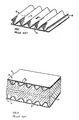
- Figure 1 illustrates a conventional protective kraft paper skin for use in a heat insulating panel;
- Figure 2 illustrates a convention heat insulating panel utilizing the protective skin of Figure 1;
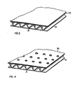
- Figure 3 illustrates a protective skin as shown in Figure 1, provided with a mat of reinforcement material in accordance with one embodiment of the present invention;
- Figure 4 is a view similar to that of Figure 3 but illustrating a further embodiment of the invention;
- Figure 5 is a sectional view of a composite employing the reinforcement mat shown in Figure 3;
- Figures 6, 7 and 8 illustrate further embodiments of the invention;
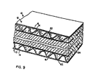
- Figure 9 is a sectional view of a composite employing the reinforcement strips shown in Figure 8;
- Figure 10 shows, in schematic form, part of a production line for manufacturing foam composites according to the invention;
- Figures 11 and 12 show, in schematic form, modified production lines specifically for manufacturing foam composites according to the embodiment of Figure 6; and
- Figure 13 illustrates a punch configuration especially suited for use in the production line of Figure 11.
- Referring now to the drawings, there is shown in Figure 1 a
protective skin 12 used in forming a conventional composite heat insulating board or panel in accordance with the present invention. Theprotective skin 12 comprises a single faced corrugated kraft paper board structure having a corrugated paper board medium 14 and anouter liner 16 adhered to the crest portions of the corrugated medium with a suitable adhesive, such as for example a wet strength adhesive. - There is shown in Figure 2 a conventional
heat insulating panel 10 which utilizes the protectivingskin 12. Thepanel 10 comprises upper and lowerprotective skins 12, 13 having acore 24 of phenolic foam material therebetween, which is dimensionally sensitive to moisture, heat and aging. - As discussed above, the foam tends to shrink after manufacture and eventually reaches an equilibrium between the shrinkage forces and the restraining forces of the skins. It will be apparent that the corrugated structure has considerably more stiffness in the direction longitudinally of the corrugations than it does across the corrugations - i.e. in the "machine" direction - than it is in the "cross-machine" direction.
- In the embodiment of the invention illustrated by Figure 3, in order to provide reinforcement in both directions - and thus provide uniformity of restraint to the shrinkage of the foam - a mat of
porous reinforcement material 30 is provided across the spices or tips of the corrugation 14 and is secured thereto by adhesive. Themat 30 may be in the form of fibreglass or the like, in which case a typical thickness of the mat would be about 1mm. - During the manufacturing process, the
phenolic foam 24 is sandwiched between theskins 12 and 13 - which have themats 30 applied thereto - and is cured. The raising phenolic foam is forced through the pores of themat 30 and fills the corrugations 14 - thus not only assuring the bond between the consecutive layers offoam 24,mats 30 andcorrugated skins 12 and 13 but also encapsulating th the material of themats 30. Thus, each resin-impregnatedmat 30 provides a region of reinforcement across the tips of the corrugations 14, which greatly increases the restraining forces against shrinkage of the foam and ensures that any shrinkage which does take place is substantially uniform in the machine and cross-machine directions of the panel. The resulting structure, with the foam filling the corrugations 14, may clearly be seen in sectional view of Figure 5. - Figure 4 illustrates a further embodiment of the invention, wherein through-holes 32 are provided in the
mats 30. The through-holes facilitate communication between the phenolic foam and the corrugations 14 and allow the foam to pass through the holes 32 to fill the corrugations and thereby enhance the adhesion and reinforcement properties discussed above. - All foam composites are vulnerable to delamination during use - especially where they are subjected to rough handling, cutting, traffic, etc. Such products are especially vulnerable to delamination caused by cutting, by the sticky wheels of asphalt spreaders or by sticky boots - to all of which conditions the products are subjected to the normal course of roof construction. Resistance of delamination of the composite can be increased by provision of through holes, as in Figure 4, but modified to create, during formation of the holes, vertical regions of adhesion within the foam core. These regions are provided by
formations 34. Conveniently, they are formed from the material displaced by punching out the holes 32, as will hereinafter be described. Theformations 34 comprise rings of vertical angled fibres formed around the holes 32. The formations are not limited to a conical shape but may be, for example, pyramidal, oval, triangular, etc. - depending upon the shape of punch used to form the holes. Theformations 34 are typically formed in a grid pattern of 3.7 × 3.7cm and the project up to 1.2cm into the foam core to provide a three-dimensional matrix of bonding which enhances adhesion between the foam and the mat. Thus, there is significant improvement in the resistance of delamination of the composite especially peeling and delamination of skins (facers) used on phenolic foam cores for roof insulation. - Figure 7 illustrates a further embodiment of the invention, wherein anchor points 33 are provided upon the
mat 30. These may be in the form of small pieces of cellulosic felt or Velcro (trade mark) glued to thecontinuous mat 30. Alternatively, the anchor pieces may be formed from perforated bead board, pieces of cured closed cell phenolic foam or spots of adhesive such as epoxy or catalysed resin. In all of the foregoing, the purpose of the anchor points is to provide locally increased adhesion between thephenolic foam core 24 and themat 30 and thus further improve the tensile strength of the composite. - Figure 8 illustrates yet a further embodiment of the invention wherein, instead of a
continuous mat 30,strips 42 are employed, these being laid across the tips of the corrugations 14. As may clearly be seen from Figure 9, the resulting composite has thestrips 42 embedded in thefoam core 24, by encapsulating the strips as the foam rises and fills the corrugations. - This, it will be appreciated that the essence of the invention lies in the ability of the foam to fill the corrugations 14 and also encapsulate the reinforcement medium. Thus, if the medium is continuous, - as in the embodiment of Figure 3 - then it must be porous to enable passage of the foam therethrough. However, if it is discontinuous in the sense of having through-holes (Figures 4 and 6) or is in the form of strips (Figure 8), the medium need not be porous since the foam has unimpeded access to the corrugations.
- Figure 10 shows, in schematic form, part of the production line for manufacturing foam composites according to the invention. First and second runs of
kraft pater 12, 13 and separately fed into a forming means comprising a pair of belt conveyors 100,200, which are spaced apart by the desired thickness of the composite to be manufactured. Each kraft paper run has a continuous orapertured mat 30 of reinforcement material applied across the corrugations thereof in a previous stage (not shown) and thelayers 30 face each other as they approach the gap between belts 100,200. Thus, in cross-section, the kraft paper runs (which will form theskins 12 and 13) are as shown in Figure 3 or 4. Alternatively, each kraft paper run may have the strips of Figure 8 applied across the corrugations in a previous stage. - As an alternative to pre-applying the mats or strips to the
skins 12, 13, they may be fed separately in the manner illustrated by Figure 11. -
Foam precursor 24 is introduced into the lower kraft paper run 13 from adispenser 300 and as the lower run transports the foam into the region between thebelts sheet 30 orstrips 42 to fill the corrugations of the kraft paper. From thebelt conveyors heating tunnel 400, wherein controlled foaming and curing takes place. Of course, the apparatus illustrated in Figure 10 is entirely conventional and the invention is thus adaptable to existing production lines with minimal modifications required. - Figure 11 illustrates a modification of the production method illustrated by Figure 10, wherein means are provided for forming the through holes 32 and
conical formations 34. The top run offibreglass mat 30 is fed to thefoam 24 separately from thekraft paper run 12 and is led around a formingroller 134. Theroller 134 is provided with suitably spaced,conical punches 234 projecting from the roller surface. As the fibreglass mat passes around the forming roller, the conical punches perforate the mat and due to the "memory" of the glass fibres which are displaced into a conical ring of fibres around each hole, the displaced fibres retain their shape during subsequent processing. From the forming roller 135, the perforated mat is laid onto theuncured foaming mixture 24 with the conical rings of fibres extending downwardly into the wet, uncured foam and, thereafter, thekraft paper skin 12 is laid down onto the fibreglass mat. The composite so-formed is then transported to theheating tunnel 400. - Figure 12 illustrates the situation where both the top and
bottom skins 12 and 13 have fibreglass reinforcement mats which are fed separately from the kraft paper runs and are led around formingrollers 134. - The precise pattern, size and shape of the
projections 34 may be varied to provide optimum delamination resistance for specific situations. In practice, we have found that rounded conical punches produce the most effective results (see Figure 13). The relatively blunt edges of the punches are found to displace the fibres to an adequate height from the mat surface and also over a relatively wide area. Sharp, conical punches were found to result in adequate vertical displacement but lower area coverage. Other shapes demonstrated significantly inferior results. Thus, it is believed that best results are likely to be derived from use of conical or rounded punches which break apart the fibreglass matrix and displace the fibres rather than cleanly cutting through the mat.
Claims (16)
1. A foam composite comprising first and second opposed corrugated skins having corrugation with inwardly facing spices and a core of foam material between the opposed inwardly facing surfaces of said skins, characterised in that there is a permeable layer of reinforcement material across the spices of one or each of the skins on the side adjacent the foam, and the foam extends through the permeable layer and into contact with the corrugations.
2. A composite according to claim 1 wherein the reinforcement on one or each of said skins is a mat of porous or apertured reinforcement material extended across the spices of said corrugations and said foam extends through the pores of apertures of each said mat to fill the spaces defined by the inwardly facing surfaces of said corrugations and embed said reinforcement material within said foam.
3. A foam composite as defined in claim 2 wherein said reinforcement material is fibreglass.
4. A composite according to claim 1 wherein the reinforcement on one or each of said skins is a plurality of strips of rigid reinforcement material, spaced apart and extending across the spices of said corrugations, and said foam extends through the gaps between said strips to fill the spaces defined by the inwardly facing surfaces of said corrugations and embed said strips of reinforcement material within said foam.
5. A composite according to claim 4 wherein said reinforcement material is selected from fibreglass, steel strapping, cellulosic felt, gypsum paper and extruded polymer profile.
6. A composite according to claim 2 or claim 3 wherein the or each said mat is provided with a plurality of through-holes through which said foam extends.
7. A composite according to claim 6 wherein each said through hole is surrounded by a ring of fibres displaced from said mat during formation of said through-holes and extending into said foam.
8. A composite according to claim 6 wherein each said through-hole is surrounded by a conically tapering ring of fibres displaced from said mat during formation of said through-holes and extending into said foam.
9. A composite according to any of claim 2, 3 or 6 to 8 wherein the or each said mat is provided with a plurality of anchor points secured to said mat on its surface adjacent said foam core and providing locally increased adhesion between said foam and said mat.
10. A composite according to any of claim 9 wherein anchor points are in the form of pieces of cellulosic felt, Velcro, bead board, or phenolic foam, or spots of epoxy or catalysed resin adhesive.
11. A composite according to any preceding claim wherein said corrugated skins are kraft paper.
12. A composite according to any preceding claim wherein said foam is selected from closed-celled or open-celled phenolic foam, urethane and isocyanurate foams.
13. A composite according to any preceding claim wherein said foam is a closed-cell phenolic foam and the skins are of kraft paper.
14. A composite according to any preceding claim in which the said reinforcement is provided on both skins.
15. A method of manufacturing a foam composite comprising first and second opposed corrugated skins having corrugations with inwardly facing spices and a core of closed cell foam material between the opposed inwardly facing surfaces of said skins, characterised in that a permeable reinforcement material is applied across the spices of at least one said skin, and applying uncured foaming mixture between said skins and foaming the mixture through the reinforcement material.
16. A method according to claim 15 and which is performed in a manner so as to produce a composite as defined in any of claims 1 to 14.
Applications Claiming Priority (2)
| Application Number | Priority Date | Filing Date | Title |
|---|---|---|---|
| CA532004 | 1987-03-13 | ||
| CA532004 | 1987-03-13 |
Publications (2)
| Publication Number | Publication Date |
|---|---|
| EP0282337A2 true EP0282337A2 (en) | 1988-09-14 |
| EP0282337A3 EP0282337A3 (en) | 1989-04-26 |
Family
ID=4135177
Family Applications (1)
| Application Number | Title | Priority Date | Filing Date |
|---|---|---|---|
| EP88302163A Withdrawn EP0282337A3 (en) | 1987-03-13 | 1988-03-11 | Reinforcement of foam composites |
Country Status (4)
| Country | Link |
|---|---|
| US (1) | US4861642A (en) |
| EP (1) | EP0282337A3 (en) |
| JP (1) | JPS6420128A (en) |
| NO (1) | NO881094L (en) |
Cited By (7)
| Publication number | Priority date | Publication date | Assignee | Title |
|---|---|---|---|---|
| EP1979147A1 (en) | 2006-01-30 | 2008-10-15 | Kingsplan Holdings (IRL) Limited | A phenolic foam board |
| WO2010040004A1 (en) | 2008-10-01 | 2010-04-08 | The Boeing Company | Composite truss panel having fluted core and sitffener made of foam and method for making the same |
| FR2994881A1 (en) * | 2012-08-28 | 2014-03-07 | Cera | METHOD FOR PRODUCING A CARRIER TRIM PANEL |
| US8834667B2 (en) | 2010-10-19 | 2014-09-16 | The Boeing Company | Method for joining sandwich truss core panels and composite structures produced therefrom |
| EP2971398A4 (en) * | 2013-03-15 | 2016-08-10 | Certainteed Gypsum Inc | BUILDING PANEL WITH ACOUSTIC FOAM |
| US20160303922A1 (en) * | 2013-10-24 | 2016-10-20 | Bentley Motors Limited | Tyre cavity noise absorber |
| US11753817B2 (en) | 2016-12-15 | 2023-09-12 | Certainteed Gypsum, Inc. | Plaster boards and methods for making them |
Families Citing this family (9)
| Publication number | Priority date | Publication date | Assignee | Title |
|---|---|---|---|---|
| SE501682C2 (en) * | 1992-08-24 | 1995-04-24 | Ericsson Karl Gustav | Disc construction and process for making them |
| US5366723A (en) * | 1993-03-05 | 1994-11-22 | Istvan Tulok | Method of alleviating toxicity originating from treatment with anticancer platinum compounds |
| US6205728B1 (en) * | 1997-04-30 | 2001-03-27 | Frank Sutelan | Laminated composite building component |
| CA2422365C (en) * | 2000-09-13 | 2009-03-03 | Serge Meilleur | Insulated formwork panels and process for their manufacture |
| US6711872B2 (en) | 2001-07-30 | 2004-03-30 | International Paper Company | Lightweight panel construction |
| GB0327065D0 (en) * | 2003-11-20 | 2003-12-24 | Intier Automotive Interiors Lt | Apparatus and method for positioning reinforcement material within an interior trim panel |
| US8381471B2 (en) * | 2005-12-09 | 2013-02-26 | Stephen C. Kobre | Packaging/construction material to make variable sized structures with intrinsic cushioning |
| WO2012162684A2 (en) * | 2011-05-25 | 2012-11-29 | E. I. Du Pont De Nemours And Company | Closed-cell tannin-based foams without formaldehyde |
| WO2024254366A1 (en) * | 2023-06-09 | 2024-12-12 | Dow Global Technologies Llc | Method for producing corrugated laminated panels |
Family Cites Families (9)
| Publication number | Priority date | Publication date | Assignee | Title |
|---|---|---|---|---|
| FR1243545A (en) * | 1958-10-06 | 1960-10-14 | Owens Corning Fiberglass Corp | Fibro-cellular product and its manufacturing process |
| US3467569A (en) * | 1966-06-03 | 1969-09-16 | Dow Chemical Co | Resin foam-metal laminate composites |
| US3637459A (en) * | 1970-03-17 | 1972-01-25 | Dow Chemical Co | Structural panel having foam plastic core |
| US4091142A (en) * | 1974-04-23 | 1978-05-23 | Dura-Plex Industries, Inc. | Structural panel and method of making same |
| US4077821A (en) * | 1975-09-15 | 1978-03-07 | Detroit Gasket Company | Method of forming foam laminates and headliners |
| US4227356A (en) * | 1978-03-23 | 1980-10-14 | Exxon Research & Engineering Co. | Composite foam roof insulation |
| US4358498A (en) * | 1980-09-24 | 1982-11-09 | Chavannes Marc A | Reinforced laminated and corrugated board-like structures and method for the manufacturing thereof |
| US4425396A (en) * | 1982-09-28 | 1984-01-10 | The B. F. Goodrich Company | Insulative panel |
| US4500596A (en) * | 1983-07-18 | 1985-02-19 | Lee Jimmy D | Polyurethane foamed in-situ against skin terpolymer comprising ethylene and propylene |
-
1988
- 1988-03-09 US US07/165,748 patent/US4861642A/en not_active Expired - Fee Related
- 1988-03-11 JP JP63056524A patent/JPS6420128A/en active Pending
- 1988-03-11 NO NO881094A patent/NO881094L/en unknown
- 1988-03-11 EP EP88302163A patent/EP0282337A3/en not_active Withdrawn
Cited By (14)
| Publication number | Priority date | Publication date | Assignee | Title |
|---|---|---|---|---|
| EP1979147A1 (en) | 2006-01-30 | 2008-10-15 | Kingsplan Holdings (IRL) Limited | A phenolic foam board |
| US9586379B2 (en) | 2008-10-01 | 2017-03-07 | The Boeing Company | Joining curved composite sandwich panels |
| WO2010040004A1 (en) | 2008-10-01 | 2010-04-08 | The Boeing Company | Composite truss panel having fluted core and sitffener made of foam and method for making the same |
| US8815038B2 (en) | 2008-10-01 | 2014-08-26 | The Boeing Company | Joining curved composite sandwich panels |
| US10293572B2 (en) | 2008-10-01 | 2019-05-21 | The Boeing Company | Method for joining sandwich truss core panels and composite structures produced therefrom |
| US8834667B2 (en) | 2010-10-19 | 2014-09-16 | The Boeing Company | Method for joining sandwich truss core panels and composite structures produced therefrom |
| FR2994881A1 (en) * | 2012-08-28 | 2014-03-07 | Cera | METHOD FOR PRODUCING A CARRIER TRIM PANEL |
| US10731337B2 (en) | 2013-03-15 | 2020-08-04 | Certainteed Gypsum, Inc. | Building board with acoustical foam |
| EP2971398A4 (en) * | 2013-03-15 | 2016-08-10 | Certainteed Gypsum Inc | BUILDING PANEL WITH ACOUSTIC FOAM |
| US11536022B2 (en) | 2013-03-15 | 2022-12-27 | Certainteed Gypsum, Inc. | Building board with acoustical foam |
| US12110680B2 (en) | 2013-03-15 | 2024-10-08 | Certainteed Gypsum, Inc. | Building board with acoustical foam |
| US20160303922A1 (en) * | 2013-10-24 | 2016-10-20 | Bentley Motors Limited | Tyre cavity noise absorber |
| US11186126B2 (en) * | 2013-10-24 | 2021-11-30 | Bentley Motors Limited | Tyre cavity noise absorber |
| US11753817B2 (en) | 2016-12-15 | 2023-09-12 | Certainteed Gypsum, Inc. | Plaster boards and methods for making them |
Also Published As
| Publication number | Publication date |
|---|---|
| US4861642A (en) | 1989-08-29 |
| NO881094L (en) | 1988-09-14 |
| JPS6420128A (en) | 1989-01-24 |
| NO881094D0 (en) | 1988-03-11 |
| EP0282337A3 (en) | 1989-04-26 |
Similar Documents
| Publication | Publication Date | Title |
|---|---|---|
| US4861642A (en) | Reinforcement of phenolic foams composite | |
| US5834082A (en) | Reinforced foam cores and method and apparatus of production | |
| US5066531A (en) | Variable thickness foam plank | |
| US6030483A (en) | Method of forming laminates using a tessellated core | |
| US4418108A (en) | Composite roofing panel | |
| US4798756A (en) | Laminate structure of interior finishing material | |
| MX9706921A (en) | Polyisocyanurate boards with reduced moisture absorbency and lower air permeability and related methods. | |
| CA2216027A1 (en) | Composite roofing members having improved dimensional stability and related methods | |
| US5876835A (en) | Molded stressed-skin panels | |
| US20050086905A1 (en) | Shear wall panel | |
| US3506533A (en) | Porous products of foamed polymeric materials and method of producing same | |
| JPS60229745A (en) | Sheet-shaped sandwich structure | |
| US4279958A (en) | Composite foam panel | |
| JPH0528179B2 (en) | ||
| JPH10505025A (en) | Sandwich panel made of starch foam | |
| AU2007209000A1 (en) | A phenolic foam board | |
| US4877671A (en) | Reducing shrinkage of phenolic foam composites | |
| CA1210557A (en) | Pattern matrix having uniform backer thickness | |
| US4673614A (en) | Roof insulation board and method of making | |
| EP0038091B1 (en) | Energy absorbing structure, esp. for skis | |
| JP2559276B2 (en) | Core material for automobile interior | |
| SE1450978A1 (en) | Method for producing a sandwich panel | |
| US7674356B2 (en) | Paper machine belt | |
| EP0048582A1 (en) | Composite building slab and method and apparatus for making slabs | |
| US4501794A (en) | Phenolic foam composites and process for making them |
Legal Events
| Date | Code | Title | Description |
|---|---|---|---|
| PUAI | Public reference made under article 153(3) epc to a published international application that has entered the european phase |
Free format text: ORIGINAL CODE: 0009012 |
|
| AK | Designated contracting states |
Kind code of ref document: A2 Designated state(s): DE GB NL SE |
|
| PUAL | Search report despatched |
Free format text: ORIGINAL CODE: 0009013 |
|
| AK | Designated contracting states |
Kind code of ref document: A3 Designated state(s): DE GB NL SE |
|
| STAA | Information on the status of an ep patent application or granted ep patent |
Free format text: STATUS: THE APPLICATION IS DEEMED TO BE WITHDRAWN |
|
| 18D | Application deemed to be withdrawn |
Effective date: 19891027 |