EP0281490A1 - Multi-purpose apparatus for the production and distribution of powdery animal feedstuffs - Google Patents
Multi-purpose apparatus for the production and distribution of powdery animal feedstuffs Download PDFInfo
- Publication number
- EP0281490A1 EP0281490A1 EP88450008A EP88450008A EP0281490A1 EP 0281490 A1 EP0281490 A1 EP 0281490A1 EP 88450008 A EP88450008 A EP 88450008A EP 88450008 A EP88450008 A EP 88450008A EP 0281490 A1 EP0281490 A1 EP 0281490A1
- Authority
- EP
- European Patent Office
- Prior art keywords
- tank
- products
- mixing unit
- unit
- mixing
- Prior art date
- Legal status (The legal status is an assumption and is not a legal conclusion. Google has not performed a legal analysis and makes no representation as to the accuracy of the status listed.)
- Ceased
Links
Images


Classifications
-
- A—HUMAN NECESSITIES
- A23—FOODS OR FOODSTUFFS; TREATMENT THEREOF, NOT COVERED BY OTHER CLASSES
- A23N—MACHINES OR APPARATUS FOR TREATING HARVESTED FRUIT, VEGETABLES OR FLOWER BULBS IN BULK, NOT OTHERWISE PROVIDED FOR; PEELING VEGETABLES OR FRUIT IN BULK; APPARATUS FOR PREPARING ANIMAL FEEDING- STUFFS
- A23N17/00—Apparatus specially adapted for preparing animal feeding-stuffs
- A23N17/007—Apparatus specially adapted for preparing animal feeding-stuffs for mixing feeding-stuff components
Definitions
- the present invention relates to a general-purpose installation for the manufacture and distribution of pulverulent feed for animals.
- the invention aims to propose an installation capable of carrying out the loading, weighing, mixing and fractional distribution operations of all types of powdered food, both dry and wet, such as corn in particular, all of the operations for transferring products to be treated, from one station to another and including the upstream phases (recovery of the starting products) and downstream (distribution to places of consumption) being carried out pneumatically.
- the existing installations or devices are not designed to integrate the entire chain of transfers between the various weighing, grinding and mixing stations, from storage. starting products to the place of consumption.
- corn intended for feeding pigs in France suffers from a major problem. After harvesting, it requires drying in order to be stored and this operation tends to become more and more expensive.
- This product does not keep when in contact with air for more than one to two hours, which means that the product has to be desiled twice a day and practically prohibits the use of automatic chains in which the product tends to ferment between two distributions.
- this product tends to compress and to vault, generally causing a blockage in all mechanical systems based on worms or pellets in tubes.
- the invention therefore aims to overcome these drawbacks by offering a total solution to the mechanization of the manufacture of food from dry products as well as non-dry products such as wet cereals in powder form.
- the subject of the invention is a multipurpose installation for the manufacture and distribution of pulverulent feed for animals, characterized in that it comprises: - a grinding-mixing assembly mounted on a weighing device and comprising a grinding unit consisting of a hopper for waiting products to be ground and a grinder, and a mixing unit consisting of a tank provided internally with 'a brewing system and connected to the grinding unit; - a plurality of fixed silos for storing different products or ingredients to be mixed, in powder or granular form, dry or wet, connected by flexible pipes to the grinding unit or to the mixing unit; a pneumatic distribution system for the mixed ground products, connected, on the one hand, to the extraction orifice of said mixing unit, on the other hand, to a silo for storing the finished product and, finally, to a or several distribution devices of the latter; - a pneumatic suction-compression system connected to the grinding unit, the mixing unit and the distribution system, and - a microcomputer automaton connected to the weighing device
- Such an installation constitutes a total chain of integral mechanization ensuring the link between the storage of the products used in the composition of the finished food and the animal lodges.
- this installation is capable of ensuring the total mechanization of the production of food from wet cereals in powder form while all the systems currently proposed go through the liquid phase (making a soup by adding water ) which poses the adaptation problems mentioned above.
- FIG. 1 The installation shown very diagrammatically in FIG. 1 comprises an assembly mounted on a chassis 1, called a weighing frame, and consisting of a grinding unit 2 and a mixing unit 3.
- a weighing means has been symbolized at 4 supporting the chassis 1 and connected to a microcomputer automaton 5 and responsible for sending thereto data relating to the instantaneous real weight of the assembly. 1-2-3.
- This weighing means can be strain gauges which are well known and need not be described in more detail.
- the grinding unit consists of a vertical cylindrical sealed tank 6, extended at the bottom by a cone trunk 7, at the bottom end of which is placed in the elbow evacuation, an automatic valve symbolized at 8, connected to the automaton 5.
- the evacuation elbow of the holding hopper constituted by the assembly 6-7 is connected to a grinder 9.
- a pipe 10 provided with an automatic valve 11 and itself connected to two separate, fixed silos, 12 and 13, by means of two pipes 14 and 15, each provided an automatic valve, 16 and 17, the valves 11, 16 and 17 being of course connected to the automaton.
- Silos 12 and 13 contain, for example, wheat and soy respectively in powder or granular form.
- the grinder 9 can be constituted by any of the known grinding devices used in animal feed.
- the mixing unit 3 consists for example of a horizontal sealed cylindrical tank 18 in which are arranged two coaxial turns 19 and 20, creating two opposite currents in the mass of the products to be mixed.
- the two turns are integral with the same horizontal shaft 21 sealingly passing through the tank 18 at each end, one of the ends of the shaft being driven in rotation by means of a geared motor 22 fixed to the tank and connected to the controller 5.
- the crusher 9 is connected to the tank 18 by a pipe 23 opening into a decompression cyclone 24 surmounted by a detent sleeve 25.
- the cyclone 24 communicates with the upper part of the tank 18 by means of an automatic valve symbolized at 26, connected to the automaton 5.
- the extraction of the finished product is done by a pipe 29 crossing the pan 27 and emerging in the center of the fabric 28.
- Line 29 is connected in parallel to various devices, for example a fixed silo 31 for finished food, a battery of cyclones 32 for filling animal lodges, via a line 33 and bypass valves connected to the automaton 5, a manual distribution cyclone 34 via a pipe 35, or a pair of portable cyclones 36 mounted on a mobile carriage automatically controlled by the automaton 5.
- the cyclones 36 are connected, by two pipes each provided with an automatic valve symbolized at 37 and connected to the automaton 5, to a main pipe 38 connected to the pipe 29.
- Automatic valves symbolized at 39 are provided at the start of each supply pipe for the devices 31 , 32, 34 and 36, these valves being connected to the automaton 5.
- the tank 18 is also directly connected by a pipe 40 to a silage screw 41 of a silo 42 with powdery wet corn, as well as to a reserve 43 with powdery minerals by means of a pipe 44.
- the silos 42 and reserve 43 are stationary and the pipes 40 and 44 are provided with automatic valves symbolized at 45 and 46 and connected to the machine 5 as well as the silage screw 41.
- the installation comprises a motor-compressor-vacuum pump group 47, mounted fixed and connected by a pipe 48 to a dispensing ramp 49 secured to the tank and shown in more detail in FIG. 3.
- the ramp 49 is connected by a pipe 50 provided with an automatic valve 51, to an air filter symbolized at 52 placed inside and in the upper part of the tank 6.
- the ramp 49 is connected by a pipe 53 provided with an automatic valve 54 to a suction filter 55 placed in the upper part in the tank 18.
- the ramp 49 is connected by a pipe 56 provided with an automatic valve 57 to the pan 27 for fluidization.
- the ramp 49 is connected by a pipe 58 provided with an automatic valve 59, to the pipe 29, between the pan 27 and the valve 30.
- the ramp 49 is, finally, connected by a pipe 60 provided with an automatic valve 61, to the pipe 29, downstream of the valve 30.
- the ramp 49 is provided with a pressure safety valve 62 and a vacuum safety valve 63.
- Valves 51, 54, 57, 59 and 61 are of course connected to the PLC 5.
- the introduction of the product (s) to be ground is done by suction using group 47.
- the latter can be of any type and must be capable of changing quickly and simply from operating under pressure to operating under vacuum.
- a particularly practical and economical way of producing a vacuum pump-compressor system capable of being used in the installation according to the invention consists in using a slurry tank compressor by changing the normal pallets equipping this type of device by special paddles allowing this compressor to work for at least one hour continuously.
- All the pipes also have non-return valves, whether in the pressure network or in the empty network.
- the pressures, depressions and flow rates are very variable depending on the working conditions, namely: nature of the product to be treated, length and section of the pipes, yield and flow rate of solid sought.
- the group 47 makes it possible, via the ramp 49 and the pipe 53, to transfer minerals from the reserve 43 directly into the tank 18 via the pipe 44, desiled wet corn from the silo 42 directly into the tank 18 via the pipe 40.
- the group 47 makes it possible to extract the finished product from the tank 18 to send it via the line 29 in one of the devices 31, 32, 34, 36 of your choice.
- the group 47 sends pressurized air to the tank 18 through the line 53, fluidizing air in the pan 27 through the line 56, secondary extraction air in the line 29 upstream (primary dilution) and downstream of the valve 30, respectively by the lines 58 and 60.
- the combination of the valve 30 and the additional air line 60 makes it possible to create air separations in the line 29 and individualize the doses of food during transport in the latter.
- the automaton 5 of course manages the whole process from the selective sampling of the product (s) or ingredients to the sending of the finished product into the appropriate device (s) via the valves (30,37,39, etc. ..).
- the microcomputer of the automaton can be of any type provided that it can manage the operations of loading, formulation, grinding, mixing, distribution and of course weighing of the various products or ingredients to be mixed.
- valves of the installation are, for example, valves controlled by jacks themselves actuated on command from the controller 5.
- the tank 18 can optionally be provided laterally with a fabric fluidization device supplied with air from the group 47, if this proves necessary in particular to avoid compaction and the phenomenon of arch in the tank 18 and to obtain correct extraction. and regular especially in the case of wet products such as corn.
- the stirring system using the two turns 19 and 20 in the tank 18 can be replaced by any other system capable of obtaining the same result.
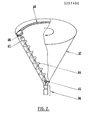
- FIG. 2 illustrates an alternative embodiment of the mixing unit according to which the tank 18 ⁇ is frustoconical with the tip down and the internal stirring system consists of a screw 64 secured to a shaft driven in rotation, by the intermediate a universal joint 65, by a geared motor 66 fixed to the lower end of the tank 18 ⁇ .
- the upper end of the screw-holding shaft 64 drives, by a reducer 67, a pinion 68 engaged with a ring gear or the like 69 inside and at the upper part of the tank 18 ⁇ , means being provided to prevent any disengagement between the pinion and the crown during movement oscillating of the screw 64 along the frustoconical wall.
- the double movement of the screw 64 ensures excellent mixing by raising the product located near the wall of the tank and taking up this product once dropped into the lower part of the tank.
- the extraction of the product is carried out laterally in the lower part of the tank 18 ⁇ , that is to say at the right of the universal joint 65, with the help of a fluidization fabric supplied with air from the ramp dispenser 49, the extraction orifice and the fluidizing fabric not being shown for the sake of clarity, in FIG. 2.
- the tank of unit 3 can also be cylindrical-conical with a vertical axis, the stirring system being for example constituted by a vertical screw rotating inside a tube and whose rotation ensures the recovery at the bottom of the products. and their rise in the upper part of the tank.
- a system for filtering the air for pressurizing or vacuuming the tank as well as possibly a filtering sleeve disposed in the mass of the product and responsible for fluidizing the latter and avoiding any compaction (in the case of wet corn in particular).
- unit 3 may include additional product inlets allowing direct connection with product silos that do not require grinding, or already ground, unit 3 filling with product directly, by suction, according to the quantities in weight programmed in the microcomputer of the automaton.
- the unit 2 can be omitted if there is no need to grind the products, in which case only the unit 3 is subjected to continuous weighing.
- the grinding unit 2 could be also at a fixed station, only unit 3 being subjected to continuous weighing.
- the invention is obviously not limited to the embodiments shown and described above, but on the contrary covers all variants thereof, in particular with regard to the nature and arrangement of the mixing unit 3, of the system. internal mixing unit 3, continuous weighing system, or device (s) for distributing the finished product.
Abstract
Description
La présente invention a trait à une installation polyvalente pour la fabrication et la distribution d'aliments pulvérulents pour animaux.The present invention relates to a general-purpose installation for the manufacture and distribution of pulverulent feed for animals.
L'invention vise à proposer une installation capable d'effectuer les opérations de chargement, pesage, mélange et distribution fractionnée de tous types d'aliments pulvérulents, aussi bien secs qu'humides tels le maïs notamment, l'ensemble des opérations de transfert des produits à traiter, d'un poste à l'autre et y compris les phases d'amont (reprise des produits de départ) et d'aval (distribution sur les lieux de consommation) étant effectuées de manière pneumatique.The invention aims to propose an installation capable of carrying out the loading, weighing, mixing and fractional distribution operations of all types of powdered food, both dry and wet, such as corn in particular, all of the operations for transferring products to be treated, from one station to another and including the upstream phases (recovery of the starting products) and downstream (distribution to places of consumption) being carried out pneumatically.
La préparation et la distribution d'aliments pour animaux posent encore divers problèmes qui ne sont pas résolus.The preparation and distribution of animal feed still poses a number of unresolved problems.
C'est ainsi que dans le domaine de la préparation et la distribution d'aliments pulvérulents secs, les installations ou dispositifs existants ne sont pas conçus pour intégrer toute la chaîne des transferts entre les divers postes de pesage, broyage et mélange, depuis le stockage des produits de départ jusqu'à l'endroit de la consommation.Thus, in the field of preparation and distribution of dry powdered food, the existing installations or devices are not designed to integrate the entire chain of transfers between the various weighing, grinding and mixing stations, from storage. starting products to the place of consumption.
D'autre part, ces dispositifs sont totalement inaptes au traitement d'aliments pulvérulents humides tel le maïs.On the other hand, these devices are totally unsuitable for the treatment of moist powdery foods such as corn.
En effet, le maïs destiné à l'alimentation du porc en France souffre d'un problème majeur. Après la récolte, il nécessite un séchage afin de pouvoir être conservé et cette opération tend à devenir de plus en plus onéreuse.Indeed, corn intended for feeding pigs in France suffers from a major problem. After harvesting, it requires drying in order to be stored and this operation tends to become more and more expensive.
Pour pallier ce problème, il a été mis au point une méthode de conservation par voie humide.To overcome this problem, a wet storage method has been developed.
Malheureusement, ce produit ainsi transformé possède des inconvénients majeurs.Unfortunately, this product thus transformed has major drawbacks.
Ce produit ne se conserve pas lorsqu'il est au contact de l'air pendant plus d'une à deux heures, ce qui oblige à un désilage du produit deux fois par jour et interdit pratiquement l'emploi de chaînes automatiques dans lesquelles le produit tend à fermenter entre deux distributions.This product does not keep when in contact with air for more than one to two hours, which means that the product has to be desiled twice a day and practically prohibits the use of automatic chains in which the product tends to ferment between two distributions.
De plus, ce produit a tendance à se comprimer et à voûter en entraînant en général un bourrage dans tous les systèmes mécaniques à base de vis sans fin ou de pastille sous tube.In addition, this product tends to compress and to vault, generally causing a blockage in all mechanical systems based on worms or pellets in tubes.
Les systèmes de distribution qui ont permis de trouver une solution acceptable sont tous basés sur le principe de l'alimentation en soupe ce qui, d'une part, entraîne des investissements très lourds et, d'autre part, n'est pas adaptable aux porcheries déjà construites puisque la soupe nécessite un sol en caillebotis intégral.The distribution systems which made it possible to find an acceptable solution are all based on the principle of the soup supply which, on the one hand, involves very heavy investments and, on the other hand, is not adaptable to pigsties already built since the soup requires a full slatted floor.
L'invention a donc pour but de pallier ces inconvénients en offrant une solution totale de la mécanisation de la fabrication d'aliments à partir de produits secs tout aussi bien que de produits non secs tels que des céréales humides se présentant sous forme pulvérulente.The invention therefore aims to overcome these drawbacks by offering a total solution to the mechanization of the manufacture of food from dry products as well as non-dry products such as wet cereals in powder form.
A cet effet, l'invention a pour objet une installation polyvalente de fabrication et distribution d'aliments pulvérulents pour animaux, caractérisée en ce qu'elle comprend :
- un ensemble de broyage-mélangeage monté sur un dispositif de pesage et comportant une unité de broyage constituée d'une trémie d'attente des produits à broyer et d'un broyeur, et une unité de mélangeage constituée d'une cuve munie intérieurement d'un système de brassage et reliée à l'unité de broyage;
- une pluralité de silos fixes de stockage de différents produits ou ingrédients à mélanger, sous forme pulvérulente ou granulaire sèche ou humide, reliés par des canalisations souples à l'unité de broyage ou à l'unite de mélangeage ;
- un système de distribution pneumatique des produits broyés mélangés, relié, d'une part, à l'orifice d'extraction de ladite unité de mélangeage, d'autre part, à un silo de stockage du produit fini et, enfin, à un ou plusieurs dispositifs de distribution de ce dernier ;
- un système pneumatique d'aspiration-compression relié à l'unité de broyage, à l'unité de mélangeage et au système de distribution, et
- un automate à micro-ordinateur relié au dispositif de pesage, au système d'aspiration-compression et à diverses vannes pneumatiques interposées dans les canalisations ou conduits de liaison entre les différents silos, unités et dispositifs ci-dessus et susceptible de commander sélectivement et successivement les opérations d'aspiration des différents produits dans la trémie d'attente de l'unité de broyage ou dans la cuve de l'unité de mélangeage, le broyage et/ou le mélangeage des produits, l'évacuation sous pression du produit fini, de l'unité de mélangeage vers le système de distribution et son envoi sélectif dans ledit silo de stockage du produit fini ou dans l'un desdits dispostifs de distribution.To this end, the subject of the invention is a multipurpose installation for the manufacture and distribution of pulverulent feed for animals, characterized in that it comprises:
- a grinding-mixing assembly mounted on a weighing device and comprising a grinding unit consisting of a hopper for waiting products to be ground and a grinder, and a mixing unit consisting of a tank provided internally with 'a brewing system and connected to the grinding unit;
- a plurality of fixed silos for storing different products or ingredients to be mixed, in powder or granular form, dry or wet, connected by flexible pipes to the grinding unit or to the mixing unit;
a pneumatic distribution system for the mixed ground products, connected, on the one hand, to the extraction orifice of said mixing unit, on the other hand, to a silo for storing the finished product and, finally, to a or several distribution devices of the latter;
- a pneumatic suction-compression system connected to the grinding unit, the mixing unit and the distribution system, and
- a microcomputer automaton connected to the weighing device, to the suction-compression system and to various pneumatic valves interposed in the pipes or connecting conduits between the various silos, units and devices above and capable of selectively controlling and successively the suction operations of the various products in the holding hopper of the grinding unit or in the tank of the mixing unit, the grinding and / or mixing of the products, the evacuation under pressure of the finished product , from the mixing unit to the distribution system and its selective dispatch to said finished product storage silo or to one of said distribution devices.
Une telle installation constitue une chaîne totale de mécanisation intégrale assurant la liaison entre le stockage des produits entrant dans la composition de l'aliment fini et les loges des animaux.Such an installation constitutes a total chain of integral mechanization ensuring the link between the storage of the products used in the composition of the finished food and the animal lodges.
En particulier, cette installation est capable d'assurer la mécanisation totale de la fabrication d'aliment à partir de céréales humides sous forme pulvérulente alors que tous les systèmes actuellement proposés passent par la phase liquide (réalisation d'une soupe par addition d'eau) ce qui pose les problèmes d'adaptation évoqués plus haut.In particular, this installation is capable of ensuring the total mechanization of the production of food from wet cereals in powder form while all the systems currently proposed go through the liquid phase (making a soup by adding water ) which poses the adaptation problems mentioned above.
D'autres caractéristiques et avantages ressortiront de la description qui va suivre de divers modes et variantes de réalisation de l'installation selon l'invention, description donnée à titre d'exemple uniquement et en regard des dessins annexés sur lesquels :
- - Figure 1 est une vue schématique générale de l'installation selon l'invention ;
- - Figure 2 illustre une variante de réalisation de l'unité de mélangeage, et
- - Figure 3 est une vue schématique des circuits pneumatiques interposés entre le système d'aspiration-compression, l'unité de broyage, l'unité de mélangeage et le système d'évacuation du produit fini.
- - Figure 1 is a general schematic view of the installation according to the invention;
- FIG. 2 illustrates an alternative embodiment of the mixing unit, and
- - Figure 3 is a schematic view of the pneumatic circuits interposed between the suction-compression system, the grinding unit, the mixing unit and the discharge system of the finished product.
L'installation représentée très schématiquement sur la figure 1 comprend un ensemble monté sur un châssis 1, dit de pesage, et constitué d'une unité de broyage 2 et d'une unité de mélangeage 3.The installation shown very diagrammatically in FIG. 1 comprises an assembly mounted on a
N'importe quel système de pesage de l'ensemble 1-2-3 peut être utilisé. Sur le schéma de la figure 1 on a symbolisé en 4 un moyen de pesage supportant le châssis 1 et relié à un automate à micro-ordinateur 5 et chargé d'envoyer à celui-ci des données relatives au poids réel instantané de l'ensemble 1-2-3. Ce moyen de pesage peut être des jauges de contraintes qui sont bien connues et n'ont pas besoin d'être décrites plus en détail.Any weighing system in the 1-2-3 set can be used. In the diagram of FIG. 1, a weighing means has been symbolized at 4 supporting the
Afin que le pesage soit le plus précis possible, toutes les canalisations ou liaisons entre les unités 2 et 3 et les autres parties de l'installation sont souples et doivent permettre un libre débattement de l'ensemble 1-3 sans que celui-ci soit entravé par lesdites canalisations ou liaisons.So that the weighing is as precise as possible, all the pipes or connections between the
Le pesage en continu de l'ensemble 1 à 3 permet d'effectuer de manière précise la distribution fractionnée de l'aliment fini.Continuous weighing of the
Dans le mode de réalisation schématisé sur la figure 1, l'unité de broyage est constituée d'une cuve étanche cylindrique verticale 6, prolongée en partie inférieure par un tronc de cone 7, à l'extrémité inférieure duquel est placée, dans le coude d'évacuation, une vanne automatique symbolisée en 8, reliée à l'automate 5.In the embodiment shown schematically in Figure 1, the grinding unit consists of a vertical cylindrical sealed tank 6, extended at the bottom by a cone trunk 7, at the bottom end of which is placed in the elbow evacuation, an automatic valve symbolized at 8, connected to the automaton 5.
Le coude d'évacuation de la trémie d'attente constituée par l'ensemble 6-7 est relié à un broyeur 9.The evacuation elbow of the holding hopper constituted by the assembly 6-7 is connected to a grinder 9.
A la partie supérieure de la cuve 6 est piquée une canalisation 10 munie d'une vanne automatique 11 et reliée elle-même à deux silos séparés, fixes, 12 et 13, par l'intermédiaire de deux canalisations 14 et 15, chacune munie d'une vanne automatique, 16 et 17, les vannes 11, 16 et 17 étant bien entendu reliées à l'automate.At the upper part of the tank 6 is punctured a
Les silos 12 et 13 contiennent par exemple respectivement du blé et du soja sous forme pulvérulente ou granulaire.
Le broyeur 9 peut être constitué par l'un quelconque des dispositifs de broyage connus utilisés dans l'alimentation des animaux.The grinder 9 can be constituted by any of the known grinding devices used in animal feed.
L'unité de mélangeage 3 est constituée par exemple d'une cuve cylindrique étanche horizontale 18 dans laquelle sont disposées deux spires à pas contraires 19 et 20, coaxiales, créant deux courants opposés dans la masse des produits à mélanger. Les deux spires sont solidaires d'un même arbre horizontal 21 traversant de manière étanche la cuve 18 à chaque extrémité, l'une des extrémités de l'arbre étant entraînée en rotation par l'intermédiaire d'un moto-réducteur 22 fixé à la cuve et relié à l'automate 5.The
Le broyeur 9 est relié à la cuve 18 par une canalisation 23 débouchant dans un cyclone de décompression 24 surmonté d'une manche de détente 25.The crusher 9 is connected to the
Le cyclone 24 communique avec la partie supérieure de la cuve 18 par l'intermédiaire d'une vanne automatique symbolisée en 26, reliée à l'automate 5.The
A l'une des extrémités de la cuve 18 et à sa partie inférieure est disposée une pièce 27 en forme de casserole rapportée sur la cuve et munie intérieurement d'une toile fluidisante 28. L'extraction du produit fini se fait par une canalisation 29 traversant la casserole 27 et débouchant au centre de la toile 28.At one end of the
Dans la canalisation 29 est disposée une vanne automatique symbolisée en 30 et reliée à l'automate 5.In the
La canalisation 29 est reliée en parallèle à divers dispositifs, par exemple un silo fixe 31 à aliment fini, une batterie de cyclones 32 de remplissage de loges d'animaux, par l'intermédiaire d'une canalisation 33 et de vannes de dérivation reliées à l'automate 5, un cyclone de distribution manuelle 34 via une canalisation 35, ou une paire de cyclones baladeurs 36 montés sur un chariot mobile automatiquement commandé par l'automate 5. Les cyclones 36 sont reliés, par deux canalisations munies chacune d'une vanne automatique symbolisée en 37 et reliée à l'automate 5, à une canalisation principale 38 reliée à la canalisation 29. Des vannes automatiques symbolisées en 39 sont prévues au départ de chaque canalisation d'alimentation des dispositifs 31,32,34 et 36, ces vannes étant reliées à l'automate 5.
La cuve 18 est par ailleurs reliée directement par une canalisation 40 à une vis désileuse 41 d'un silo 42 à maïs humide pulvérulent, ainsi qu'à une réserve 43 à minéraux pulvérulents par l'intermédiaire d'une canalisation 44.The
Les silo 42 et réserve 43 sont à poste fixe et les canalisations 40 et 44 sont munies de vannes automatiques symbolisées en 45 et 46 et reliées à l'automate 5 ainsi que la vis désileuse 41.The
Tous les transferts des produits pulvérulents ou granuleux s'opérent dans l'installation de manière pneumatique, soit par aspiration, soit par propulsion.All transfers of powdery or granular products take place in the installation pneumatically, either by suction or by propulsion.
A cet effet, l'installation comprend un groupe moto-compresseur-pompe à vide 47, monté fixe et relié par une canalisation 48 à une rampe distributrice 49 solidaire de la cuve et représentée plus en détail à la figure 3.To this end, the installation comprises a motor-compressor-
La rampe 49 est reliée par une canalisation 50 munie d'une vanne automatique 51, à un filtre à air symbolisé en 52 disposé à l'intérieur et en partie haute de la cuve 6.The
La rampe 49 est reliée par une canalisation 53 munie d'une vanne automatique 54 à un filtre d'aspiration 55 disposé en partie haute dans la cuve 18.The
La rampe 49 est reliée par une canalisation 56 munie d'une vanne automatique 57 à la casserole 27 de fluidisation.The
La rampe 49 est reliée par une canalisation 58 munie d'une vanne automatique 59, à la canalisation 29, entre la casserole 27 et la vanne 30.The
La rampe 49 est, enfin, reliée par une canalisation 60 munie d'une vanne automatique 61, à la canalisation 29, en aval de la vanne 30.The
Par ailleurs, la rampe 49 est munie d'une soupape de sécurité en pression 62 et d'une soupape de sécurité en dépression 63.Furthermore, the
Les vannes 51,54,57,59 et 61 sont bien entendu reliées à l'automate 5.Valves 51, 54, 57, 59 and 61 are of course connected to the PLC 5.
L'installation décrite ci-dessus peut opérer de différentes manières, car elle est polyvalente, sous la commande entièrement automatisée de l'automate 5.The installation described above can operate in different ways, because it is versatile, under the fully automated control of PLC 5.
L'introduction du ou des produits à broyer se fait par aspiration à l'aide du groupe 47. Ce dernier peut être de tout type et doit être capable de passer de manière simple et rapide du fonctionnement en pression au fonctionnement en dépression.The introduction of the product (s) to be ground is done by
Une manière particulièrement pratique et économique de réaliser un système compresseur-pompe à vide susceptible d'être utilisé dans l'installation selon l'invention, consiste à employer un compresseur de tonne à lisier en changeant les palettes normales équipant ce type d'appareil par des palettes spéciales permettant à ce compresseur de travailler pendant au minimum une heure en continu.A particularly practical and economical way of producing a vacuum pump-compressor system capable of being used in the installation according to the invention, consists in using a slurry tank compressor by changing the normal pallets equipping this type of device by special paddles allowing this compressor to work for at least one hour continuously.
Toutes les canalisations comportent par ailleurs des clapets anti-retour que ce soit dans le réseau pression ou dans le réseau vide.All the pipes also have non-return valves, whether in the pressure network or in the empty network.
Les pressions, dépressions et débits sont très variables selon les conditions de travail à savoir : nature du produit à traiter, longueur et section des canalisations, rendement et débit de solide recherché.The pressures, depressions and flow rates are very variable depending on the working conditions, namely: nature of the product to be treated, length and section of the pipes, yield and flow rate of solid sought.
En fonctionnement aspiration le groupe 47 permet, via la rampe 49 et la canalisation 53, de transférer des minéraux de la réserve 43 directement dans la cuve 18 par la canalisation 44, du maïs humide désilé du silo 42 directement dans la cuve 18 par la canalisation 40.In suction operation, the
Il permet aussi de transférer des produits des silos 12 et 13, au choix, dans l'unité de broyage 2 via la rampe 49 et les canalisations 10 et 50.It also makes it possible to transfer products from
En position pression, le groupe 47 permet d'extraire le produit fini de la cuve 18 pour l'envoyer par la canalisation 29 dans l'un des dispositifs 31,32,34,36 au choix.In the pressure position, the
A cet effet, le groupe 47 envoie de l'air sous pression dans la cuve 18 par la canalisation 53, de l'air de fluidisation dans la casserole 27 par la canalisation 56, de l'air secondaire d'extraction dans la canalisation 29 en amont (dilution primaire) et en aval de la vanne 30, respectivement par les canalisations 58 et 60. La combinaison de la vanne 30 et de la canalisation d'air additionnel 60 permet de créer des séparations d'air dans la canalisation 29 et d'individualiser les doses d'aliment en cours de transport dans cette dernière.To this end, the
L'automate 5 gère bien entendu tout le processus depuis le prélèvement sélectif du ou des produits ou ingrédients jusqu'à l'envoi du produit fini dans le ou les dispositifs appropriés par l'intermédiaire des vannes (30,37,39,etc...). Le micro-ordinateur de l'automate peut être d'un type quelconque pourvu qu'il puisse gérer les opérations de chargement, de formulation, de broyage, de mélange, distribution et bien entendu de pesage des divers produits ou ingrédients à mélanger.The automaton 5 of course manages the whole process from the selective sampling of the product (s) or ingredients to the sending of the finished product into the appropriate device (s) via the valves (30,37,39, etc. ..). The microcomputer of the automaton can be of any type provided that it can manage the operations of loading, formulation, grinding, mixing, distribution and of course weighing of the various products or ingredients to be mixed.
Les différentes vannes de l'installation sont par exemple des vannes commandées par des vérins eux-mêmes actionnés sur commande de l'automate 5.The various valves of the installation are, for example, valves controlled by jacks themselves actuated on command from the controller 5.
La cuve 18 peut être éventuellement munie latéralement d'un dispositif de fluidisation à toile alimentée en air à partir du groupe 47, si cela s'avère nécessaire notamment pour éviter le compactage et le phénomène de voûte dans la cuve 18 et obtenir une extraction correcte et régulière en particulier dans le cas de produits humides tel le maïs.The
Il est à noter que l'inversion du fonctionnement du groupe 47 permet de nettoyer automatiquement les filtres 52 et 55.It should be noted that reversing the operation of
Le système de brassage à l'aide des deux spires 19 et 20 dans la cuve 18 peut être remplacé par tout autre système susceptible de procurer le même résultat.The stirring system using the two turns 19 and 20 in the
La figure 2 illustre une variante de réalisation de l'unité de mélangeage suivant laquelle la cuve 18ʹ est tronconique avec la pointe en bas et le système de brassage interne est constitué par une vis 64 solidaire d'un arbre entraîné en rotation, par l'intermédiaire d'un joint de cardan 65, par un moto-réducteur 66 fixé à l'extrémité inférieure de la cuve 18ʹ.Figure 2 illustrates an alternative embodiment of the mixing unit according to which the tank 18ʹ is frustoconical with the tip down and the internal stirring system consists of a
L'extrémité supérieure de l'arbre porte-vis 64 entraîne, par un réducteur 67, un pignon 68 en prise avec une couronne dentée ou analogue 69 à l'intérieur et à la partie supérieure de la cuve 18ʹ, des moyens étant prévus pour empêcher tout désengrènement entre le pignon et la couronne lors du mouvement oscillant de la vis 64 le long de la paroi tronconique.The upper end of the screw-holding
Le double mouvement de la vis 64 (rotation autour de son axe et rotation autour de l'axe de la cuve 18ʹ) assure un excellent mélange par remontée du produit se trouvant au voisinage de la paroi de la cuve et reprise de ce produit une fois retombé dans la partie inférieure de la cuve.The double movement of the screw 64 (rotation about its axis and rotation around the axis of the tank 18ʹ) ensures excellent mixing by raising the product located near the wall of the tank and taking up this product once dropped into the lower part of the tank.
L'extraction du produit s'effectue latéralement en partie inférieure de la cuve 18ʹ, c'est-à-dire au droit du joint de cardan 65, avec l'aide d'une toile de fluidisation alimentée en air à partir de la rampe distributrice 49, l'orifice d'extraction et la toile fluidisante n'étant pas représentés par souci de clarté, sur la figure 2.The extraction of the product is carried out laterally in the lower part of the tank 18ʹ, that is to say at the right of the
La cuve de l'unité 3 peut aussi être cylindro-conique d'axe vertical, le système de brassage étant par exemple constitué par une vis verticale tournant à l'intérieur d'un tube et dont la rotation assure la reprise en bas des produits et leur remontée en partie haute de la cuve.The tank of
Dans le cas d'une cuve d'axe vertical il est également prévu, en partie haute, un système de filtration de l'air de mise en pression ou dépression de la cuve, ainsi qu'éventuellement une manche filtrante disposée dans la masse du produit et chargée de fluidiser ce dernier et d'éviter tout compactage (cas du maïs humide notamment).In the case of a tank with a vertical axis, there is also provided, in the upper part, a system for filtering the air for pressurizing or vacuuming the tank, as well as possibly a filtering sleeve disposed in the mass of the product and responsible for fluidizing the latter and avoiding any compaction (in the case of wet corn in particular).
Il est à noter que l'unité 3 peut comporter des entrées de produit supplémentaires permettant le raccordement direct avec des silos à produits ne nécessitant pas de broyage, ou déjà broyés, l'unité 3 se remplissant en produit directement, par aspiration, selon les quantités en poids programmées dans le micro-ordinateur de l'automate.It should be noted that
Dans l'installation telle que représentée en figure 1, l'unité 2 peut être supprimée s'il n'y a pas nécessité de broyer les produits, auquel cas seule l'unité 3 est soumise à un pesage en continu.In the installation as shown in FIG. 1, the
Par ailleurs, l'unité de broyage 2 pourrait être également à poste fixe, seule l'unité 3 étant soumise à un pesage en continu.Furthermore, the grinding
Enfin, l'invention n'est évidemment pas limitée aux modes de réalisation représentés et décrits ci-dessus mais en couvre au contraire toutes les variantes notamment en ce qui concerne la nature et l'agencement de l'unité de mélangeage 3, du système de brassage interne à l'unité 3, du système de pesage en continu, du ou des dispositifs de distribution du produit fini.Finally, the invention is obviously not limited to the embodiments shown and described above, but on the contrary covers all variants thereof, in particular with regard to the nature and arrangement of the
Claims (7)
- un ensemble de broyage-mélangeage monté sur un dispositif de pesage (4) et comportant une unité de broyage (2) constituée d'une trémie (6) d'attente des produits à broyer et d'un broyeur (9), et une unité de mélangeage (3) constituée d'une cuve (18,18ʹ) munie intérieurement d'un système de brassage (19,20; 64) et reliée à l'unité de broyage (2);
- une pluralité de silos fixes (12,13,42,43) de stockage de différents produits ou ingrédients à mélanger, sous forme pulvérulente ou granulaire sèche ou humide, reliés par des canalisations souples à l'unité de broyage (2) ou à l'unite de mélangeage (3) ;
- un système (29) de distribution pneumatique des produits broyés mélangés, relié, d'une part, à l'orifice d'extraction de ladite unité de mélangeage (3), d'autre part, à un silo (31) de stockage du produit fini et, enfin, à un ou plusieurs dispositifs (32,34,36) de distribution de ce dernier ;
- un système pneumatique d'aspiration-compression (47) relié à l'unité de broyage (2), à l'unité de mélangeage (3) et au système de distribution (29), et
- un automate à micro-ordinateur (5) relié au dispositif de pesage (4), au système d'aspiration-compression (47) et à diverses vannes pneumatiques interposées dans les canalisations ou conduits de liaison entre les différents silos, unités et dispositifs ci-dessus et susceptible de commander sélectivement et successivement les opérations d'aspiration des différents produits dans la trémie d'attente (6) de l'unité de broyage (2) ou dans la cuve (18,18ʹ) de l'unité de mélangeage (3), le broyage et/ou le mélangeage des produits, l'évacuation sous pression du produit fini, de l'unité de mélangeage (3) vers le système de distribution (29) et son envoi sélectif dans ledit silo de stockage (31) du produit fini ou dans l'un desdits dispositifs de distribution (32,34,36).1. Multipurpose installation for the manufacture and distribution of pulverulent feed for animals, characterized in that it comprises:
a grinding-mixing assembly mounted on a weighing device (4) and comprising a grinding unit (2) consisting of a hopper (6) waiting for the products to be grinded and a grinder (9), and a mixing unit (3) consisting of a tank (18,18ʹ) internally provided with a stirring system (19,20; 64) and connected to the grinding unit (2);
- a plurality of fixed silos (12,13,42,43) for storing different products or ingredients to be mixed, in powder or granular dry or wet form, connected by flexible pipes to the grinding unit (2) or to the mixing unit (3);
- A system (29) for pneumatic distribution of the comminuted mixed products, connected, on the one hand, to the extraction orifice of said mixing unit (3), on the other hand, to a storage silo (31) of the finished product and, finally, to one or more devices (32, 34, 36) for distributing the latter;
a pneumatic suction-compression system (47) connected to the grinding unit (2), to the mixing unit (3) and to the distribution system (29), and
- a microcomputer automaton (5) connected to the weighing device (4), to the suction-compression system (47) and to various pneumatic valves interposed in the pipes or connecting conduits between the different silos, units and devices above and capable of selectively and successively controlling the suction operations of the various products in the holding hopper (6) of the grinding unit (2) or in the tank (18.18ʹ) of the mixing (3), grinding and / or mixing of the products, evacuation under pressure of the finished product, from the mixing unit (3) to the distribution system (29) and its selective dispatch in said storage silo (31) of the finished product or in one of said distribution devices (32,34,36).
Applications Claiming Priority (2)
| Application Number | Priority Date | Filing Date | Title |
|---|---|---|---|
| FR8703210A FR2611445B1 (en) | 1987-03-06 | 1987-03-06 | VERSATILE PLANT FOR THE MANUFACTURE AND DISTRIBUTION OF POWDERY ANIMAL FEED |
| FR8703210 | 1987-03-06 |
Publications (1)
| Publication Number | Publication Date |
|---|---|
| EP0281490A1 true EP0281490A1 (en) | 1988-09-07 |
Family
ID=9348767
Family Applications (1)
| Application Number | Title | Priority Date | Filing Date |
|---|---|---|---|
| EP88450008A Ceased EP0281490A1 (en) | 1987-03-06 | 1988-03-04 | Multi-purpose apparatus for the production and distribution of powdery animal feedstuffs |
Country Status (2)
| Country | Link |
|---|---|
| EP (1) | EP0281490A1 (en) |
| FR (1) | FR2611445B1 (en) |
Cited By (2)
| Publication number | Priority date | Publication date | Assignee | Title |
|---|---|---|---|---|
| FR2798261A1 (en) * | 1999-09-13 | 2001-03-16 | Dussau Distrib | Equipment for manufacturing animal feed has supply hoppers for grain or pulverized material connected to grinder and mixer by conduits and suction unit draws materials through conduits |
| WO2002100195A1 (en) * | 2001-06-11 | 2002-12-19 | Material Ganadero Canar S.L. | Method for obtaining complete feed for livestock |
Families Citing this family (3)
| Publication number | Priority date | Publication date | Assignee | Title |
|---|---|---|---|---|
| ES2138522B1 (en) * | 1997-02-21 | 2000-08-16 | Material Ganadero Canar S L | PROCEDURE FOR OBTAINING INTEGRAL FOOD FOR CATTLE. |
| FR2788943B1 (en) | 1999-02-01 | 2001-03-30 | Acemo | ANIMAL PRODUCTION FACILITY |
| FR2798371B1 (en) * | 1999-09-10 | 2001-11-23 | Acemo | DEVICE FOR PROVIDING THE TRANSFER OF MATERIALS FROM A DEPRESSED PART TO AN OVERPRESSED PART OF A PNEUMATIC CONVEYOR |
Citations (7)
| Publication number | Priority date | Publication date | Assignee | Title |
|---|---|---|---|---|
| FR1535632A (en) * | 1967-06-27 | 1968-08-09 | Process for the preparation of a feed base from corn cobs and installation for implementing the process | |
| FR2116596A5 (en) * | 1970-11-05 | 1972-07-21 | Vincent Victor | |
| US3806001A (en) * | 1972-04-18 | 1974-04-23 | Micro Chem Inc | Feed formulation system and process |
| FR2406397A1 (en) * | 1977-10-24 | 1979-05-18 | Nagy Johann | ADDITIONER APPLIANCE FOR MIXING ANIMAL FEEDS, INTENDED FOR AGRICULTURAL STORAGE FACILITIES |
| GB1554692A (en) * | 1978-01-19 | 1979-10-24 | Hughes Steel Prod Ltd | Mixer for animal feedstuufs |
| FR2501012A1 (en) * | 1981-03-06 | 1982-09-10 | Denizot Jean Georges | Packaged installation to produce cereal based animal feed - has weighing, milling, mixing and bag filling machines on common base frame |
| DE3321731A1 (en) * | 1983-06-16 | 1984-12-20 | Weda-Dammann & Westerkamp GmbH, 2849 Goldenstedt | Device for producing dry mixed cattle feed on the farm itself |
-
1987
- 1987-03-06 FR FR8703210A patent/FR2611445B1/en not_active Expired
-
1988
- 1988-03-04 EP EP88450008A patent/EP0281490A1/en not_active Ceased
Patent Citations (7)
| Publication number | Priority date | Publication date | Assignee | Title |
|---|---|---|---|---|
| FR1535632A (en) * | 1967-06-27 | 1968-08-09 | Process for the preparation of a feed base from corn cobs and installation for implementing the process | |
| FR2116596A5 (en) * | 1970-11-05 | 1972-07-21 | Vincent Victor | |
| US3806001A (en) * | 1972-04-18 | 1974-04-23 | Micro Chem Inc | Feed formulation system and process |
| FR2406397A1 (en) * | 1977-10-24 | 1979-05-18 | Nagy Johann | ADDITIONER APPLIANCE FOR MIXING ANIMAL FEEDS, INTENDED FOR AGRICULTURAL STORAGE FACILITIES |
| GB1554692A (en) * | 1978-01-19 | 1979-10-24 | Hughes Steel Prod Ltd | Mixer for animal feedstuufs |
| FR2501012A1 (en) * | 1981-03-06 | 1982-09-10 | Denizot Jean Georges | Packaged installation to produce cereal based animal feed - has weighing, milling, mixing and bag filling machines on common base frame |
| DE3321731A1 (en) * | 1983-06-16 | 1984-12-20 | Weda-Dammann & Westerkamp GmbH, 2849 Goldenstedt | Device for producing dry mixed cattle feed on the farm itself |
Cited By (3)
| Publication number | Priority date | Publication date | Assignee | Title |
|---|---|---|---|---|
| FR2798261A1 (en) * | 1999-09-13 | 2001-03-16 | Dussau Distrib | Equipment for manufacturing animal feed has supply hoppers for grain or pulverized material connected to grinder and mixer by conduits and suction unit draws materials through conduits |
| WO2002100195A1 (en) * | 2001-06-11 | 2002-12-19 | Material Ganadero Canar S.L. | Method for obtaining complete feed for livestock |
| ES2178973A1 (en) * | 2001-06-11 | 2003-01-01 | Material Ganadero Canar S L | Method for obtaining complete feed for livestock |
Also Published As
| Publication number | Publication date |
|---|---|
| FR2611445A1 (en) | 1988-09-09 |
| FR2611445B1 (en) | 1989-06-30 |
Similar Documents
| Publication | Publication Date | Title |
|---|---|---|
| CN113083453A (en) | Raw material pretreatment system for rose essence extraction and raw material pretreatment method thereof | |
| CN107262204A (en) | A kind of vertical feed lapping device of intermittent charging | |
| EP0281490A1 (en) | Multi-purpose apparatus for the production and distribution of powdery animal feedstuffs | |
| CN207254402U (en) | A kind of vertical feed lapping device of intermittent charging | |
| CN109398786A (en) | A kind of pair of dried wolfberry carries out the technique for being packaged processing | |
| US3200859A (en) | Hollow-centered compacting device | |
| FR2798371A1 (en) | Transfer device for use in manufacturing animal feed has Archimedes screw in housing with normally closed valve at outlet and has inlet at lower air pressure than outlet | |
| US3501101A (en) | Mobile feed grinding and mixing and distributing apparatus | |
| CN214802141U (en) | Premixed type aleurone layer flour production line | |
| EP0276645A1 (en) | Method for mixing and distributing animal feed, and rotating machine for realising this method | |
| US2850052A (en) | Butter handling apparatus | |
| EP1321262A1 (en) | Installation for manufacturing and transporting of mortar | |
| CN113975997A (en) | Cosmetics allotment unloading system | |
| CN112547203A (en) | Glutinous rice grinding device | |
| FR2540400A1 (en) | Method and installation for mixing fibrous products and products in the divided state, and application in the agricultural field for adjusting a mixture for feeding herbivorous animals | |
| RU2331191C1 (en) | Feed mixer-distributor | |
| CN218988207U (en) | Efficient feeding device for ruminant feed production | |
| CN220721449U (en) | Automatic tea packaging machine | |
| FR2586170A1 (en) | Device for manufacturing feed for cattle | |
| SU1818028A1 (en) | Fodder preparation and dispensing plant | |
| EP0141703B1 (en) | Apparatus for the preparation of an animal foodstuff | |
| FR2673121A1 (en) | MIXER. | |
| CN219844793U (en) | Automatic pulp supplementing machine for food processing | |
| CN211303365U (en) | Corn starch processing equipment convenient to remove | |
| CN212099624U (en) | Powder packing plant |
Legal Events
| Date | Code | Title | Description |
|---|---|---|---|
| PUAI | Public reference made under article 153(3) epc to a published international application that has entered the european phase |
Free format text: ORIGINAL CODE: 0009012 |
|
| AK | Designated contracting states |
Kind code of ref document: A1 Designated state(s): BE DE NL |
|
| 17P | Request for examination filed |
Effective date: 19890228 |
|
| 17Q | First examination report despatched |
Effective date: 19900705 |
|
| STAA | Information on the status of an ep patent application or granted ep patent |
Free format text: STATUS: THE APPLICATION HAS BEEN REFUSED |
|
| 18R | Application refused |
Effective date: 19910727 |