EP0280667B1 - A valve mechanism for an internal combustion engine - Google Patents
A valve mechanism for an internal combustion engine Download PDFInfo
- Publication number
- EP0280667B1 EP0280667B1 EP88850040A EP88850040A EP0280667B1 EP 0280667 B1 EP0280667 B1 EP 0280667B1 EP 88850040 A EP88850040 A EP 88850040A EP 88850040 A EP88850040 A EP 88850040A EP 0280667 B1 EP0280667 B1 EP 0280667B1
- Authority
- EP
- European Patent Office
- Prior art keywords
- lifting arm
- arm
- valve
- rocker
- shaft
- Prior art date
- Legal status (The legal status is an assumption and is not a legal conclusion. Google has not performed a legal analysis and makes no representation as to the accuracy of the status listed.)
- Expired - Lifetime
Links
Images
Classifications
-
- F—MECHANICAL ENGINEERING; LIGHTING; HEATING; WEAPONS; BLASTING
- F01—MACHINES OR ENGINES IN GENERAL; ENGINE PLANTS IN GENERAL; STEAM ENGINES
- F01L—CYCLICALLY OPERATING VALVES FOR MACHINES OR ENGINES
- F01L1/00—Valve-gear or valve arrangements, e.g. lift-valve gear
- F01L1/02—Valve drive
- F01L1/10—Valve drive by means of crank-or eccentric-driven rods
-
- F—MECHANICAL ENGINEERING; LIGHTING; HEATING; WEAPONS; BLASTING
- F01—MACHINES OR ENGINES IN GENERAL; ENGINE PLANTS IN GENERAL; STEAM ENGINES
- F01L—CYCLICALLY OPERATING VALVES FOR MACHINES OR ENGINES
- F01L1/00—Valve-gear or valve arrangements, e.g. lift-valve gear
- F01L1/12—Transmitting gear between valve drive and valve
- F01L1/18—Rocking arms or levers
-
- F—MECHANICAL ENGINEERING; LIGHTING; HEATING; WEAPONS; BLASTING
- F01—MACHINES OR ENGINES IN GENERAL; ENGINE PLANTS IN GENERAL; STEAM ENGINES
- F01L—CYCLICALLY OPERATING VALVES FOR MACHINES OR ENGINES
- F01L13/00—Modifications of valve-gear to facilitate reversing, braking, starting, changing compression ratio, or other specific operations
- F01L13/0015—Modifications of valve-gear to facilitate reversing, braking, starting, changing compression ratio, or other specific operations for optimising engine performances by modifying valve lift according to various working parameters, e.g. rotational speed, load, torque
- F01L13/0063—Modifications of valve-gear to facilitate reversing, braking, starting, changing compression ratio, or other specific operations for optimising engine performances by modifying valve lift according to various working parameters, e.g. rotational speed, load, torque by modification of cam contact point by displacing an intermediate lever or wedge-shaped intermediate element, e.g. Tourtelot
Definitions
- the present invention relates to a valve mechanism intended for controlling a poppet valve in an internal combustion engine and comprising a control shaft which is driven by the engine crank shaft, and a push rod which is reciprocally driven by the control shaft and which for the purpose of transmitting reciprocal movement is connected to a first arm of a two-arm rocker which is pivotable about a rocker shaft and the other arm of which transmits said movements to the valve, the first arm of the rocker extending substantially at right angles to the push rod and the second arm of the rocker extending substantially parallel with the geometric longitudinal airs of the valve, a lifting arm being provided for transmission of rocker movement to the valve, the second arm of the rocker being provided with actuating means for co-action with the lifting arm.
- control shaft normally comprises a cam shaft for actuation of a push rod, connected to one arm of a rocker, the other arm of which normally acts upon the valve directly, possibly via an intermediate valve lifter.
- Such valve mechanisms have a simple construction and are reliable in operation.
- valve mechanisms of this kind the times at which the valve is opened and closed and also the height to which the valve is lifted is determined by the configuration of the cam on the cam shaft and by the transmission ratio of the rocker, with regard to valve lifting height. Consequently, in order to change the valve opening and closing times, or the valve lifting height, it is necessary to redesign the valve mechanism and/or to change the cam shaft.
- Fr-A-2032705 discloses a valve mechanism which is a development of the conventional valve mechanism and which corresponds substantially to the valve mechanism described in the first paragraph of this description.
- the object of this invention is to provide a valve mechanism which will make it possible to utilize the advantages obtainable with, e.g., the aforementioned systems designed for controlling the working cycle of internal combustion engines.
- This object is achieved with an inventive valve mechanism having the characteristic features set forth in the characterizing clause of claim 1.
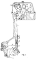
- the valve mechanism illustrated in Figure 1 is fitted to an internal combustion engine, the major parts of which are of conventional construction and are not therefore shown in detail here.
- the valve mechanism is intended to control the movements of a valve 1, of which only a small part of the valve stem is shown.
- the valve mechanism includes a control shaft 2 which is intended to be driven by the engine crank shaft in the same manner as the cam shaft in a valve mechanism of the kind described in the first paragraph of this specification.
- the control shaft 2 drives a push rod 3, in a manner hereinafter described, the lower end of which is coupled to the control shaft 2 and the upper end of which is coupled to a rocker 4.
- the rocker 4 is, in turn, intended to act upon a lifting arm 5, which in turn activates the valve 1.
- control shaft 2 is provided with a crank pin 6 which is connected to a pin 8 on a control arm 9 through the intermediary of a short connecting rod 7.
- One end of the control arm 9 is pivotally mounted on a pin 10 which is fixedly mounted in the engine, whereas the other end of the control arm is pivotally connected to the lower end of the push rod 3 by means of a pin 11.
- a length adjustment means 12 is also located at the lower end of the push rod 3, in the proximity of the pin 11, by means of which the length of the push rod 3 can be adjusted so as to achieve correct functioning of the valve mechanism.
- the upper end of the push rod 3 is pivotally connected to a first arm 14 on the rocker 4 by means of a pin 13.
- the rocker 4 is a double-arm rocker and is journalled on a rocker shaft 15, which is stationarily fitted to the engine.
- the free end of the other rocker arm 16 carries a roller 18 which is journalled for rotation on a pin 17.
- One end of the lifting arm 5 is journalled on a lifting-arm shaft 19, which is fitted stationarily to the engine. As beforementioned, the free end of the lifting arm 5 is intended to act upon the valve 1 when the lifting arm 5 is swung about its shaft 19.
- the upper side of the lifting arm 5 presents a profiled surface 20 which consists of three parts 20a, 20b, 20c of mutually different curvature, as described in more detail hereinafter.
- the profiled surface 20 is intended to co-act with the roller 18 on the rocker 4 so as to produce desired movements of the valve 1.
- the part 20a of the profiled surface is convex and partly cylindrical, and has a radius of curvature such that its centre of curvature coincides essentially with the geometric axis of the rocker shaft 15. This means that when the roller 18 moves over the surface part 20a, in response to rocker movement, the lifting arm 5 is held essentially stationary.
- the surface part 20b adjoins the surface part 20a at the end thereof distal from the lifting arm shaft 19 and has a concave curvature. This means that when the roller 18 moves in over the surface part 20b, the lifting arm will be pressed downwards and will in turn press down the valve 1, causing the valve to open. In this regard, the speed at which the valve is opened, and to which extent, is determined by the diameter of the roller 18 and the curvature of the surface part 20b.
- the surface part 20b is thus curved in the same direction as the peripheral surface of the roller 18, although the radius of curvature of the surface part 20b is larger than the diameter of the roller 18. Because the roller 18 and the surface part 20b are curved in the same direction but have mutually different radii of curvature, it is possible to obtain greater acceleration in valve opening movements than can be obtained with prior art valve mechanisms, without overloading the components.
- This enables the method described in Swedish Patent Application 8503517-8 to be carried out in a particularly simple manner, according to which method the engine exhaust valve is opened a second time during each working cycle of the engine.
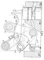
- Figure 2 illustrates a second embodiment of the inventive valve mechanism.
- Those components of the Figure 2 embodiment which find direct correspondence with the Figure 1 embodiment are identified with the same reference numerals, and the lower part of the push rod 3 and the push-rod drive mechanism have been omitted in the Figure 2 illustration.
- the valve mechanism illustrated in Figure 2 operates essentially in the same manner as the valve mechanism illustrated in Figure 1.
- the valve mechanism according to Figure 2 affords a further possibility of adjusting the mutual relationship between the roller 18 on the free end of the other rocker arm 16 and the surface part 20a, 20b and 20c of the profiled surface on the lifting arm 5.
- This further possibility has been provided by mounting the lifting arm shaft 19 of the Figure 2 embodiment on a plate 21 which can be swung around the geometric axis of the rocker shaft 15 and which can be locked firmly in desired positions by means of a lock screw 22.
- a setting screw 23 co-acts with the plate 21, to enable the plate to be adjusted to the position desired.
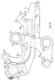
- Figure 3 illustrates a further embodiment of the inventive valve mechanism, wherewith those components which find direct correspondence in the aforedescribed embodiments have been identified with the same reference numerals. Further engine components have been omitted in the Figure 3 embodiment.
- the lifting arm 5 of the Figure 3 embodiment consists of two parts, namely a first part 5a which is journalled on the lifting arm shaft 19 and intended to act on the valve 1, and a second part 5b which is displaceably journalled on the first part 5a and incorporates the profiled surface 20 having the surface parts 20a, 20b and 20c.
- the second part 5b of the lifting arm 5 is provided with a surface 24 which faces the first part 5a and which is part-cylindrical and has a radius such that its centre of curvature coincides essentially with the geometric axis of the rocker shaft 15. As shown in Figure 3, the surface 24 abuts shoulders 25 on the first part 5a of the lifting arm 5.
- the end of the second part 5b facing the lifting arm shaft 19 is provided with a pin 26.
- the lifting arm shaft 19 is also provided with a crankpin 27 and a connecting rod 28 is connected between the crank pin 27 and the pin 26. Rotation of the lifting arm shaft 19 causes the connecting rod 28 to displace the pin 26 axially, under the influence of the crankpin 27, therewith displacing the whole of the second part 5b of the lifting arm 5, this displacement of the lifting arm part 5b being effected through abutment between the surface 24 on the second part 5b and the shoulders 25 on the first part 5a.
- valve mechanism also enables the valve to be opened very rapidly, without the surface pressures between mutually co-acting component parts becoming too high. Because movements of the rocker are guided positively in both directions of movement, the mass of those component parts which are accelerated with the aid of valve springs when closing the valve is also reduced in comparison with the case in prior art valve mechanisms of this kind.
- these component parts namely comprise solely the valve 1 and the lifting arm 5.
Abstract
Description
- The present invention relates to a valve mechanism intended for controlling a poppet valve in an internal combustion engine and comprising a control shaft which is driven by the engine crank shaft, and a push rod which is reciprocally driven by the control shaft and which for the purpose of transmitting reciprocal movement is connected to a first arm of a two-arm rocker which is pivotable about a rocker shaft and the other arm of which transmits said movements to the valve, the first arm of the rocker extending substantially at right angles to the push rod and the second arm of the rocker extending substantially parallel with the geometric longitudinal airs of the valve, a lifting arm being provided for transmission of rocker movement to the valve, the second arm of the rocker being provided with actuating means for co-action with the lifting arm.
- In conventional valve mechanisms used in various types of internal combustion engine the control shaft normally comprises a cam shaft for actuation of a push rod, connected to one arm of a rocker, the other arm of which normally acts upon the valve directly, possibly via an intermediate valve lifter. Such valve mechanisms have a simple construction and are reliable in operation. In valve mechanisms of this kind, the times at which the valve is opened and closed and also the height to which the valve is lifted is determined by the configuration of the cam on the cam shaft and by the transmission ratio of the rocker, with regard to valve lifting height. Consequently, in order to change the valve opening and closing times, or the valve lifting height, it is necessary to redesign the valve mechanism and/or to change the cam shaft.
- Fr-A-2032705 discloses a valve mechanism which is a development of the conventional valve mechanism and which corresponds substantially to the valve mechanism described in the first paragraph of this description.
- In recent years different systems have been developed for improving the wording sequence in the cylinders of internal combustion engines so that combustion is more complete and engine efficiency is increased, these developments being undertaken for reasons of economy and in order to decrease the emission of harmful constituents in the exhaust gases from internal combustion engines. A number of such systems are described in Swedish Patent Applications 8503517-8; 8700115-2 and 8700116-0. The advantages afforded by these systems, however, can not be utilized to the full with valve mechanisms of the aforedescribed kind, and it is therefore necessary to compromise and avail upon these advantages within a relatively limited part of the working range of the engine.
- Accordingly, the object of this invention is to provide a valve mechanism which will make it possible to utilize the advantages obtainable with, e.g., the aforementioned systems designed for controlling the working cycle of internal combustion engines. This object is achieved with an inventive valve mechanism having the characteristic features set forth in the characterizing clause of claim 1.
- Advantageous embodiments which enhance the possibilities of utilizing the advantages afforded, e.g., by the aforementioned systems are defined in the dependent claims.
- The invention will now be described in more detail with reference to the accompanying drawings, in which
- Figure 1 is a vertical sectional view of part of an internal combustion engine fitted with a valve mechanism according to a first embodiment of the invention;
- Figure 2 is a vertical sectional view of part of a valve mechanism according to a second embodiment of the invention; and
- Figure 3 illustrates part of a valve mechanism according to a third embodiment of the invention.
- The valve mechanism illustrated in Figure 1 is fitted to an internal combustion engine, the major parts of which are of conventional construction and are not therefore shown in detail here. The valve mechanism is intended to control the movements of a valve 1, of which only a small part of the valve stem is shown. The valve mechanism includes a control shaft 2 which is intended to be driven by the engine crank shaft in the same manner as the cam shaft in a valve mechanism of the kind described in the first paragraph of this specification. The control shaft 2 drives a
push rod 3, in a manner hereinafter described, the lower end of which is coupled to the control shaft 2 and the upper end of which is coupled to arocker 4. Therocker 4 is, in turn, intended to act upon alifting arm 5, which in turn activates the valve 1. - As shown in Figure 1, the control shaft 2 is provided with a crank pin 6 which is connected to a
pin 8 on a control arm 9 through the intermediary of a short connecting rod 7. One end of the control arm 9 is pivotally mounted on apin 10 which is fixedly mounted in the engine, whereas the other end of the control arm is pivotally connected to the lower end of thepush rod 3 by means of apin 11. Also located at the lower end of thepush rod 3, in the proximity of thepin 11, is a length adjustment means 12 by means of which the length of thepush rod 3 can be adjusted so as to achieve correct functioning of the valve mechanism. - The upper end of the
push rod 3 is pivotally connected to afirst arm 14 on therocker 4 by means of apin 13. Therocker 4 is a double-arm rocker and is journalled on arocker shaft 15, which is stationarily fitted to the engine. The free end of theother rocker arm 16 carries aroller 18 which is journalled for rotation on apin 17. - One end of the
lifting arm 5 is journalled on a lifting-arm shaft 19, which is fitted stationarily to the engine. As beforementioned, the free end of thelifting arm 5 is intended to act upon the valve 1 when thelifting arm 5 is swung about itsshaft 19. - The upper side of the
lifting arm 5 presents a profiled surface 20 which consists of threeparts roller 18 on therocker 4 so as to produce desired movements of the valve 1. Thepart 20a of the profiled surface is convex and partly cylindrical, and has a radius of curvature such that its centre of curvature coincides essentially with the geometric axis of therocker shaft 15. This means that when theroller 18 moves over thesurface part 20a, in response to rocker movement, thelifting arm 5 is held essentially stationary. Thesurface part 20b adjoins thesurface part 20a at the end thereof distal from thelifting arm shaft 19 and has a concave curvature. This means that when theroller 18 moves in over thesurface part 20b, the lifting arm will be pressed downwards and will in turn press down the valve 1, causing the valve to open. In this regard, the speed at which the valve is opened, and to which extent, is determined by the diameter of theroller 18 and the curvature of thesurface part 20b. Thesurface part 20b is thus curved in the same direction as the peripheral surface of theroller 18, although the radius of curvature of thesurface part 20b is larger than the diameter of theroller 18. Because theroller 18 and thesurface part 20b are curved in the same direction but have mutually different radii of curvature, it is possible to obtain greater acceleration in valve opening movements than can be obtained with prior art valve mechanisms, without overloading the components. - The end of the
surface part 20a located nearest thelifting arm shaft 19 adjoins asurface part 20c which has a concave curvature and which through co-action with theroller 8 on therocker 4 enables the valve to be opened a second time during each working cycle of the engine. This enables the method described in Swedish Patent Application 8503517-8 to be carried out in a particularly simple manner, according to which method the engine exhaust valve is opened a second time during each working cycle of the engine. - Figure 2 illustrates a second embodiment of the inventive valve mechanism. Those components of the Figure 2 embodiment which find direct correspondence with the Figure 1 embodiment are identified with the same reference numerals, and the lower part of the
push rod 3 and the push-rod drive mechanism have been omitted in the Figure 2 illustration. - The valve mechanism illustrated in Figure 2 operates essentially in the same manner as the valve mechanism illustrated in Figure 1. The valve mechanism according to Figure 2, however, affords a further possibility of adjusting the mutual relationship between the
roller 18 on the free end of theother rocker arm 16 and thesurface part lifting arm 5. This further possibility has been provided by mounting thelifting arm shaft 19 of the Figure 2 embodiment on aplate 21 which can be swung around the geometric axis of therocker shaft 15 and which can be locked firmly in desired positions by means of alock screw 22. Asetting screw 23 co-acts with theplate 21, to enable the plate to be adjusted to the position desired. By pivoting theplate 21, which results in axial displacement of thelifting arm shaft 19, thelifting arm 5 is displaced, so as to alter the engagement between theroller 18 on therocker 4 and thesurface parts lifting arm 5. - Figure 3 illustrates a further embodiment of the inventive valve mechanism, wherewith those components which find direct correspondence in the aforedescribed embodiments have been identified with the same reference numerals. Further engine components have been omitted in the Figure 3 embodiment.
- The main difference between the embodiment illustrated in Figure 3 and the aforedescribed embodiments is that the
lifting arm 5 of the Figure 3 embodiment consists of two parts, namely a first part 5a which is journalled on thelifting arm shaft 19 and intended to act on the valve 1, and asecond part 5b which is displaceably journalled on the first part 5a and incorporates the profiled surface 20 having thesurface parts second part 5b of thelifting arm 5 is provided with asurface 24 which faces the first part 5a and which is part-cylindrical and has a radius such that its centre of curvature coincides essentially with the geometric axis of therocker shaft 15. As shown in Figure 3, thesurface 24abuts shoulders 25 on the first part 5a of thelifting arm 5. - In order to enable the
second part 5b to be displaced axially in relation to the first part 5a, the end of thesecond part 5b facing thelifting arm shaft 19 is provided with apin 26. Thelifting arm shaft 19 is also provided with acrankpin 27 and a connecting rod 28 is connected between thecrank pin 27 and thepin 26. Rotation of thelifting arm shaft 19 causes the connecting rod 28 to displace thepin 26 axially, under the influence of thecrankpin 27, therewith displacing the whole of thesecond part 5b of thelifting arm 5, this displacement of thelifting arm part 5b being effected through abutment between thesurface 24 on thesecond part 5b and theshoulders 25 on the first part 5a. This mutual movement between the liftingarm parts 5a and 5b is further guided through the mutual abutment ofprojections respective parts 5a and 5b, wherewith the mutually abutting surfaces of theprojections rocker shaft 15. - By rotating the
lifting arm shaft 19 with the aid of suitable auxiliary devices (not shown), it is possible to displace thesecond part 5b of thelifting arm 5 while the engine is running, which enables the valve opening and/or valve closing times and/or the valve lifting height to be changed with the engine running. This enables those advantages afforded by the methods described in Swedish Patent Applications 8700115-2 and 8700116-0 to be utilized to the full. - It is possible with all of the aforedescribed embodiments to select the times at which the valve 1 shall open or close, and also the height to which the valve is lifted, and also to choose whether the valve shall open once or twice during an engine cycle, by suitable dimensioning of the valve mechanism components. The inventive valve mechanism also enables the valve to be opened very rapidly, without the surface pressures between mutually co-acting component parts becoming too high. Because movements of the rocker are guided positively in both directions of movement, the mass of those component parts which are accelerated with the aid of valve springs when closing the valve is also reduced in comparison with the case in prior art valve mechanisms of this kind. In the case of the inventive valve mechanism, these component parts namely comprise solely the valve 1 and the
lifting arm 5.
Claims (8)
Priority Applications (1)
| Application Number | Priority Date | Filing Date | Title |
|---|---|---|---|
| AT88850040T ATE71184T1 (en) | 1987-02-26 | 1988-02-02 | VALVE TIMING MECHANISM FOR AN INTERNAL ENGINE. |
Applications Claiming Priority (2)
| Application Number | Priority Date | Filing Date | Title |
|---|---|---|---|
| SE8700820 | 1987-02-26 | ||
| SE8700820A SE464367B (en) | 1987-02-26 | 1987-02-26 | VALVE MECHANISM CONTROLS A DISTRICT VALVE |
Publications (2)
| Publication Number | Publication Date |
|---|---|
| EP0280667A1 EP0280667A1 (en) | 1988-08-31 |
| EP0280667B1 true EP0280667B1 (en) | 1992-01-02 |
Family
ID=20367686
Family Applications (1)
| Application Number | Title | Priority Date | Filing Date |
|---|---|---|---|
| EP88850040A Expired - Lifetime EP0280667B1 (en) | 1987-02-26 | 1988-02-02 | A valve mechanism for an internal combustion engine |
Country Status (6)
| Country | Link |
|---|---|
| US (1) | US4829949A (en) |
| EP (1) | EP0280667B1 (en) |
| JP (1) | JPS63230915A (en) |
| AT (1) | ATE71184T1 (en) |
| DE (1) | DE3867255D1 (en) |
| SE (1) | SE464367B (en) |
Families Citing this family (14)
| Publication number | Priority date | Publication date | Assignee | Title |
|---|---|---|---|---|
| GB2214570A (en) * | 1988-01-22 | 1989-09-06 | Ford Motor Co | Variable lift i.c. engine valves |
| JPH0830403B2 (en) * | 1989-12-21 | 1996-03-27 | 卓也 松本 | Engine valve drive |
| US5093974A (en) * | 1990-04-12 | 1992-03-10 | United Engineering Inc. | Bendable sleeved roll |
| GB9320204D0 (en) * | 1993-09-30 | 1993-11-17 | Lotus Car | Valve operating mechanism for internal combustion engines |
| US5791306A (en) * | 1997-08-13 | 1998-08-11 | Caterpillar Inc. | Internal combustion engine speed-throttle control |
| US6644255B1 (en) * | 1999-10-15 | 2003-11-11 | Vee Two Ptd Ltd. | Guide plate for a poppet valve |
| US6505591B1 (en) * | 2001-07-27 | 2003-01-14 | General Motors Corporation | Valve train with assembly guides |
| GB0200935D0 (en) * | 2002-01-16 | 2002-03-06 | Lotus Car | Valve operating mechanisms |
| US6736096B2 (en) * | 2002-02-21 | 2004-05-18 | Delphi Technologies, Inc. | Method and apparatus for setting valve lift within a cylinder |
| DE10312962A1 (en) * | 2003-03-24 | 2004-10-21 | Thyssen Krupp Automotive Ag | Device for actuating charge exchange valves in reciprocating engines |
| DE10342075A1 (en) * | 2003-09-10 | 2005-06-16 | Rolf Jung | Fully variable globe valve control of an internal combustion engine |
| JP4254582B2 (en) * | 2004-03-12 | 2009-04-15 | 日産自動車株式会社 | Valve lift amount adjusting mechanism and adjusting method for internal combustion engine |
| EP1712747A1 (en) * | 2005-04-17 | 2006-10-18 | Uwe Eisenbeis | Valve train with variable valve stroke and timing for high-speed engines |
| US10125642B1 (en) * | 2016-10-06 | 2018-11-13 | Competition Cams, Inc. | Length adjustable pushrod device for internal combustion engines |
Family Cites Families (7)
| Publication number | Priority date | Publication date | Assignee | Title |
|---|---|---|---|---|
| US1741677A (en) * | 1927-02-24 | 1929-12-31 | Harold F Pitcairn | Valve-adjusting means for internal-combustion engines |
| GB306212A (en) * | 1927-11-30 | 1929-02-21 | Cyril Joseph Bamford | Improvements in internal combustion engines |
| US2954017A (en) * | 1958-03-29 | 1960-09-27 | Porsche Kg | Valve control arrangement for internal combustion engines |
| GB1299673A (en) * | 1969-02-13 | 1972-12-13 | Fiat Spa | Improvements relating to valve actuating mechanisms for internal combustion engines |
| DD155634A1 (en) * | 1980-12-22 | 1982-06-23 | Erich Henker | VALVE CONTROL OF THE GENERATION COUPLING LOADING GEARBOX FOR INTERNAL COMBUSTION ENGINES |
| DE3203791A1 (en) * | 1982-02-04 | 1983-08-11 | Volkswagenwerk Ag, 3180 Wolfsburg | VALVE DRIVE, ESPECIALLY FOR A MOTOR VEHICLE INTERNAL COMBUSTION ENGINE |
| US4638773A (en) * | 1986-02-28 | 1987-01-27 | General Motors Corporation | Variable valve lift/timing mechanism |
-
1987
- 1987-02-26 SE SE8700820A patent/SE464367B/en not_active IP Right Cessation
-
1988
- 1988-02-02 EP EP88850040A patent/EP0280667B1/en not_active Expired - Lifetime
- 1988-02-02 DE DE8888850040T patent/DE3867255D1/en not_active Expired - Lifetime
- 1988-02-02 AT AT88850040T patent/ATE71184T1/en not_active IP Right Cessation
- 1988-02-08 US US07/153,717 patent/US4829949A/en not_active Expired - Lifetime
- 1988-02-26 JP JP63044095A patent/JPS63230915A/en active Pending
Also Published As
| Publication number | Publication date |
|---|---|
| SE464367B (en) | 1991-04-15 |
| SE8700820D0 (en) | 1987-02-26 |
| JPS63230915A (en) | 1988-09-27 |
| DE3867255D1 (en) | 1992-02-13 |
| US4829949A (en) | 1989-05-16 |
| SE8700820L (en) | 1988-08-27 |
| EP0280667A1 (en) | 1988-08-31 |
| ATE71184T1 (en) | 1992-01-15 |
Similar Documents
| Publication | Publication Date | Title |
|---|---|---|
| EP0280667B1 (en) | A valve mechanism for an internal combustion engine | |
| US7624711B2 (en) | Variable mechanical valve control for an internal combustion engine | |
| US6422187B2 (en) | Variable valve mechanism having an eccentric-driven frame | |
| JP2814613B2 (en) | Engine Valve Actuator | |
| US5732669A (en) | Valve control for an internal combustion engine | |
| KR20050016757A (en) | Valve-actuating device for internal combustion engine | |
| EP1669559B1 (en) | Valve Operating Mechanism | |
| EP0601570A1 (en) | Valve gear for internal combustion engine | |
| EP0963508B1 (en) | Adjustment mechanism for valves | |
| KR101585490B1 (en) | Variable valve mechanism | |
| WO1995009298A1 (en) | Valve operating mechanism for internal combustion engines | |
| EP0434331A1 (en) | Drive arrangement for valves of an internal combustion engine | |
| EP1697619B1 (en) | Variable valve gear | |
| EP1318280A2 (en) | Extended duration cam lobe for variable valve actuation mechanism | |
| CA1056241A (en) | Adjustable cam system for internal combustion engine | |
| EP0397776B1 (en) | Mechanism for achieving variable valve lift | |
| EP0125096A3 (en) | Mechanism for variably controlling an internal combustion engine valve | |
| JPH09195735A (en) | Machine for linear reciprocating motion | |
| SU1180603A1 (en) | Regulated device for converting rotary motion into reciprocation motion | |
| SU1574872A1 (en) | Valve gear of internal combustion engine with controllable phases | |
| KR960013348B1 (en) | Variable timing valve apparatus for internal combustion engine | |
| JPH02221612A (en) | Variable valve system of internal combustion engine | |
| US4862842A (en) | Arrangements for converting rotary motion into linear motion | |
| GB2082266A (en) | Driving mechanism for fuel injection pumps | |
| KR100195408B1 (en) | Valve device of variable lift type |
Legal Events
| Date | Code | Title | Description |
|---|---|---|---|
| PUAI | Public reference made under article 153(3) epc to a published international application that has entered the european phase |
Free format text: ORIGINAL CODE: 0009012 |
|
| AK | Designated contracting states |
Kind code of ref document: A1 Designated state(s): AT BE CH DE ES FR GB IT LI NL SE |
|
| 17P | Request for examination filed |
Effective date: 19890223 |
|
| 17Q | First examination report despatched |
Effective date: 19900403 |
|
| GRAA | (expected) grant |
Free format text: ORIGINAL CODE: 0009210 |
|
| ITF | It: translation for a ep patent filed |
Owner name: BARZANO' E ZANARDO ROMA S.P.A. |
|
| AK | Designated contracting states |
Kind code of ref document: B1 Designated state(s): AT BE CH DE ES FR GB IT LI NL SE |
|
| PG25 | Lapsed in a contracting state [announced via postgrant information from national office to epo] |
Ref country code: NL Effective date: 19920102 Ref country code: AT Effective date: 19920102 Ref country code: BE Effective date: 19920102 Ref country code: CH Effective date: 19920102 Ref country code: ES Free format text: THE PATENT HAS BEEN ANNULLED BY A DECISION OF A NATIONAL AUTHORITY Effective date: 19920102 Ref country code: SE Effective date: 19920102 Ref country code: LI Effective date: 19920102 |
|
| REF | Corresponds to: |
Ref document number: 71184 Country of ref document: AT Date of ref document: 19920115 Kind code of ref document: T |
|
| REF | Corresponds to: |
Ref document number: 3867255 Country of ref document: DE Date of ref document: 19920213 |
|
| ET | Fr: translation filed | ||
| REG | Reference to a national code |
Ref country code: CH Ref legal event code: PL |
|
| NLV1 | Nl: lapsed or annulled due to failure to fulfill the requirements of art. 29p and 29m of the patents act | ||
| PLBE | No opposition filed within time limit |
Free format text: ORIGINAL CODE: 0009261 |
|
| STAA | Information on the status of an ep patent application or granted ep patent |
Free format text: STATUS: NO OPPOSITION FILED WITHIN TIME LIMIT |
|
| 26N | No opposition filed | ||
| REG | Reference to a national code |
Ref country code: GB Ref legal event code: IF02 |
|
| PGFP | Annual fee paid to national office [announced via postgrant information from national office to epo] |
Ref country code: DE Payment date: 20070125 Year of fee payment: 20 |
|
| PGFP | Annual fee paid to national office [announced via postgrant information from national office to epo] |
Ref country code: GB Payment date: 20070131 Year of fee payment: 20 |
|
| PGFP | Annual fee paid to national office [announced via postgrant information from national office to epo] |
Ref country code: IT Payment date: 20070625 Year of fee payment: 20 |
|
| REG | Reference to a national code |
Ref country code: GB Ref legal event code: PE20 |
|
| PGFP | Annual fee paid to national office [announced via postgrant information from national office to epo] |
Ref country code: FR Payment date: 20070208 Year of fee payment: 20 |
|
| PG25 | Lapsed in a contracting state [announced via postgrant information from national office to epo] |
Ref country code: GB Free format text: LAPSE BECAUSE OF EXPIRATION OF PROTECTION Effective date: 20080201 |