EP0280448B1 - Fluid container port connector mounting - Google Patents
Fluid container port connector mounting Download PDFInfo
- Publication number
- EP0280448B1 EP0280448B1 EP88301221A EP88301221A EP0280448B1 EP 0280448 B1 EP0280448 B1 EP 0280448B1 EP 88301221 A EP88301221 A EP 88301221A EP 88301221 A EP88301221 A EP 88301221A EP 0280448 B1 EP0280448 B1 EP 0280448B1
- Authority
- EP
- European Patent Office
- Prior art keywords
- section
- wall
- tubular
- tubular means
- container according
- Prior art date
- Legal status (The legal status is an assumption and is not a legal conclusion. Google has not performed a legal analysis and makes no representation as to the accuracy of the status listed.)
- Expired - Lifetime
Links
- 239000012530 fluid Substances 0.000 title claims description 18
- 238000000034 method Methods 0.000 claims description 12
- 239000000463 material Substances 0.000 claims description 5
- 239000002654 heat shrinkable material Substances 0.000 claims description 4
- 238000010438 heat treatment Methods 0.000 claims description 4
- 239000012943 hotmelt Substances 0.000 claims description 3
- 239000013013 elastic material Substances 0.000 abstract 2
- 239000000853 adhesive Substances 0.000 description 11
- 230000001070 adhesive effect Effects 0.000 description 11
- 238000003780 insertion Methods 0.000 description 10
- 230000037431 insertion Effects 0.000 description 10
- 238000003466 welding Methods 0.000 description 9
- 229920003023 plastic Polymers 0.000 description 8
- 239000004033 plastic Substances 0.000 description 8
- 238000007789 sealing Methods 0.000 description 7
- 239000004698 Polyethylene Substances 0.000 description 2
- 206010046543 Urinary incontinence Diseases 0.000 description 2
- 238000012986 modification Methods 0.000 description 2
- 230000004048 modification Effects 0.000 description 2
- -1 polyethylene Polymers 0.000 description 2
- 229920000573 polyethylene Polymers 0.000 description 2
- 239000004677 Nylon Substances 0.000 description 1
- 238000005452 bending Methods 0.000 description 1
- IKZZIQXKLWDPCD-UHFFFAOYSA-N but-1-en-2-ol Chemical compound CCC(O)=C IKZZIQXKLWDPCD-UHFFFAOYSA-N 0.000 description 1
- 239000011248 coating agent Substances 0.000 description 1
- 238000000576 coating method Methods 0.000 description 1
- 229920002457 flexible plastic Polymers 0.000 description 1
- 238000004519 manufacturing process Methods 0.000 description 1
- 229920001778 nylon Polymers 0.000 description 1
- 229920001296 polysiloxane Polymers 0.000 description 1
- 239000000565 sealant Substances 0.000 description 1
Images



Classifications
-
- A—HUMAN NECESSITIES
- A61—MEDICAL OR VETERINARY SCIENCE; HYGIENE
- A61F—FILTERS IMPLANTABLE INTO BLOOD VESSELS; PROSTHESES; DEVICES PROVIDING PATENCY TO, OR PREVENTING COLLAPSING OF, TUBULAR STRUCTURES OF THE BODY, e.g. STENTS; ORTHOPAEDIC, NURSING OR CONTRACEPTIVE DEVICES; FOMENTATION; TREATMENT OR PROTECTION OF EYES OR EARS; BANDAGES, DRESSINGS OR ABSORBENT PADS; FIRST-AID KITS
- A61F5/00—Orthopaedic methods or devices for non-surgical treatment of bones or joints; Nursing devices ; Anti-rape devices
- A61F5/44—Devices worn by the patient for reception of urine, faeces, catamenial or other discharge; Colostomy devices
- A61F5/4404—Details or parts
-
- Y—GENERAL TAGGING OF NEW TECHNOLOGICAL DEVELOPMENTS; GENERAL TAGGING OF CROSS-SECTIONAL TECHNOLOGIES SPANNING OVER SEVERAL SECTIONS OF THE IPC; TECHNICAL SUBJECTS COVERED BY FORMER USPC CROSS-REFERENCE ART COLLECTIONS [XRACs] AND DIGESTS
- Y10—TECHNICAL SUBJECTS COVERED BY FORMER USPC
- Y10S—TECHNICAL SUBJECTS COVERED BY FORMER USPC CROSS-REFERENCE ART COLLECTIONS [XRACs] AND DIGESTS
- Y10S383/00—Flexible bags
- Y10S383/904—Filling tube
-
- Y—GENERAL TAGGING OF NEW TECHNOLOGICAL DEVELOPMENTS; GENERAL TAGGING OF CROSS-SECTIONAL TECHNOLOGIES SPANNING OVER SEVERAL SECTIONS OF THE IPC; TECHNICAL SUBJECTS COVERED BY FORMER USPC CROSS-REFERENCE ART COLLECTIONS [XRACs] AND DIGESTS
- Y10—TECHNICAL SUBJECTS COVERED BY FORMER USPC
- Y10S—TECHNICAL SUBJECTS COVERED BY FORMER USPC CROSS-REFERENCE ART COLLECTIONS [XRACs] AND DIGESTS
- Y10S383/00—Flexible bags
- Y10S383/906—Dispensing feature
Definitions
- the present invention relates to fluid containers designed for medical applications and, more particularly, to a container port structure and a method for mounting a tube connector to the port of a flexible plastic pouch or bag such as a urostomy pouch or a collection receptacle of a urinary incontinence system.
- Flexible pouches, bags or receptacles designed for use for medical purposes include ports which permit fluids to enter and/or exit.
- urinary incontinence systems utilize collection receptacles in the form of plastic pouches or bags.
- the pouches are provided with an inlet port connected to flexible tubing and/or an outlet port connected to a valve to permit drainage of the collected fluid. Drainage valves of various types, employing clamps, the bending or kinking of a flexible tube, plugs, rotatable valves, and the like, have been utilized for this purpose. Regardless of the type of valve or tube, it is necessary to connect same to the container port in a manner which will be completely fluid-tight and, at the same time, strong enough to withstand the physical stresses to which the container will be subjected.
- GB-A-2125294 discloses a fluid conduit comprising a port section and formed of a relatively flexible, generally cylindrical wall having a distal end, first tubular means situated within the port section, and having an outer diameter substantially equal to the inner diameter of said port section, second tubular means partially situated within said port section proximate said wall end, said first means being substantially non-elastic and the second means being relatively elastic, a portion of said second tubular means being inserted within said first tubular means, a section of said wall being sealingly engaged between the exterior surface of said second tubular means and the interior surface of said first tubular means.
- the present invention relates to a simple way of using the natural resiliency of the components to obtain a fluid-tight, physically strong seal between the tube connector and a flexible container wall, without depending upon accurate welding or complete sealing by adhesive. A very high reliability seal can be obtained without utilizing specialized or costly production equipment.
- a fluid container comprising a fluid reservoir section and a port section extending from said reservoir section and formed of a relatively flexible, generally cylindrical wall having a distal end, first tubular means situated within said port section, and having an outer diameter substantially equal to the inner diameter of said port section, second tubular means at least partially situated within said port section proximate said wall end, one of said means being substantially non-elastic and the other of said means being relatively elastic, a portion of said second tubular means being inserted within said first tubular means, a section of said wall being sealingly engaged between the exterior surface of said second tubular means and the interior surface of said first tubular means, characterised in that said port section comprises first and second substantially side-by-side portions.
- One of the portions may be affixed to the exterior surface of the second tubular means either by welding or adhesive sealing.
- the non-elastic tubular means preferably comprises a relatively rigid plastic tube.
- the elastic tubular means preferably comprises a relatively soft plastic tube.
- Detent means are preferably provided on one of the tubular means.
- Detent receiving means are preferably provided on the other of the tubular means.
- the detent means preferably comprises annular protrusion means and the detent receiving means preferably includes annular protrusion receiving means.
- one of the tubular members is in a deformed state.
- the port section preferably comprises a first portion situated adjacent the interior surface of the first member and a second portion situated adjacent the exterior surface of the second member.
- the second portion is preferably affixed to the exterior surface of the other tube either by welding or by adhesive sealing.
- the other tube preferably extends beyond the end of the one tube. In this way, it may extend into the interior of the reservoir portion of the container and form a sump.
- the one tube is preferably relatively freely received within the wall. It is preferably not glued or welded within the wall.
- a method for affixing a tubular connector member to the relatively flexible wall of the port section of a fluid container or the like comprising the steps of: placing a tubular clamping member within the port section at a location spaced from the end thereof, and forceably inserting the connector member into the clamping member so as to deform one of the members, sealingly engaging a section of said wall between the interior surface of said clamping member and the exterior surface of said connector member, characterised in that said method includes the step of placing the connector member at least partially within the port section proximate the end thereof prior to inserting the connector member into the clamping member, such that the engaged section has two portions, one of the portions being affixed to the exterior surface of the connector member and the other of the portions lying adjacent the interior surface of the clamping member.
- the clamping member is preferably composed of a heat shrinkable material or coated with a hot melt material.
- the method further comprises heating the clamping member subsequent to insertion of the connector member.
- a fluid container port connector mounting which does not depend on accurate welding or complete adhesive sealing.
- An embodiment of the invention also provides a fluid container port connector mounting which is inexpensive and reliable.
- Figs. 1 through 4 illustrate a first preferred embodiment of the present invention. Shown is the inlet or outlet port section of a fluid container such as a plastic bag or pouch, generally designated A.
- Pouch A has a fluid reservoir portion 10 and an elongated port section 12.
- Port section 12 is formed of a generally cylindrical wall made of relatively thin flexible material, such as plastic.
- Within wall 12 is placed a plastic tubular clamping member 14.
- the outer diameter of member 14 is substantially equal to or slightly greater than the inner diameter of wall 12.
- tubular member 14 is preferably not sealed to the interior of wall 12. It is either lightly or snugly received within wall 12 at a location spaced from the end 16 thereof.
- Wall 12 preferably tapers to a smaller diameter proximate end 16. Within this tapered section is received a second tubular connector member 18 with a portion thereof extending beyond the end 16 of wall 12.
- the outer diameter of member 18 is preferably substantially equal to the inner diameter of member 14.
- the exterior surface of member 18 is preferably welded or sealed to the interior surface of section 19 of wall 12 by an adhesive sealant which remains flexible after curing, such as silicone.
- One of the members 14 and 18 is composed of substantially non-elastic, preferably rigid hard plastic such as Nylon.
- the other of the members 14 and 18 is composed of a relatively elastic, preferably softer plastic such as polyethylene. In this way one of the members will deform to a small extent relative to the other when member 18 is inserted into member 14. If it is member 14 which is elastic, it will expand. If it is member 18 which is elastic, it will compress. This slight deformation will create a high clamping force between the members. If the polyethylene is used to form the connector member 18, it may be preferable to add ethyl vinyl alcohol to enhance its properties for welding to the pouch film. It is also preferable that the material of which clamping member 14 is composed be a heat shrinkable material or have an internal coating of a hot melt material. This will permit heating of the assembly to enhance the seal.
- member 18 is forceably inserted into the interior of member 14 such that a section 20 of wall 12 is captured or sealingly engaged between the wall section 19 and the interior surface of member 14.
- This causes the relatively elastic one of the tubular members to deform slightly and to create a relatively high force which tends to clamp the sections of wall 12 between the exterior surface of connector member 18 and the interior surface of clamping member 14, resulting in a fluid-tight friction seal.
- the seal is further enhanced by heating the assembly such that member 14 will shrink down or the interior layer thereof will melt, depending upon its composition.
- the section of wall 12 which is captured between tubular members 14 and 18 consists of a section 19 which is affixed to the exterior surface of tubular member 18 and section 20, which extends between the end of clamping member 14 and the end of connector member 18.
- sections 19 and 20 of wall 12 are in substantially side-by-side relation and held in tight frictional engagement therebetween by the force exerted by the deformed member.
- tubular clamping member 18 ⁇ is longer in length than clamping member 18 of the first embodiment.
- a section of member 18 ⁇ is situated within connector member 14 in its initial position.
- Member 18 ⁇ is adhesively affixed to the interior surface of wall 12 by welding or adhesive, as in the first embodiment.
- a portion 19 ⁇ of the exterior surface of the wall 12 is coated with a layer of adhesive prior to insertion of member 18 ⁇ fully within member 14.
- connector member 18 ⁇ When connector member 18 ⁇ is fully inserted within tubular member 14, as seen in Fig. 6, the end thereof extends into member 14 beyond the section of wall 12 captured therebetween.
- the adhesive-coated section 19 ⁇ of wall 12 is captured between the tubular members 14 and 18 ⁇ , facing a second portion 20 of wall 12. In this manner, section 19 ⁇ of wall 12 is adhesively sealed to section 20.
- the second preferred embodiment has an advantage over the embodiment shown in Figs. 1-4 in that the tubular members may be handled as a unit as a section of the clamping member 18 ⁇ is situated within connector member 14 before insertion into the port section of the container, In addition, the layer of adhesive on portion 19' improves the seal.
- connector member 18' of the second preferred embodiment is preferably provided with an outwardly extending annular protrusion or flange 22.
- Flange 22 may be used to connect a tube or other external member to the end of member 18' and, thus, to the port section of the container.
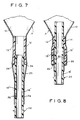
- Figs. 7 and 8 show a third preferred embodiment of the present invention.
- the third embodiment is quite similiar to the second embodiment, with the exception that detent means are provided to enhance and strengthen the seal created.
- the interior section of clamping member 14 adjacent the end thereof is provided with a detent means in a form of an annular protrusion 24.
- annular protrusion 24 aligns with annular recess 26 in the surface of member 18', as shown in Fig. 8, such that portions of wall sections 19' and 20 of wall 12 are captured therebetween in a sealing manner.
- Fig. 9 illustrates a portion of a fluid container A with the reservoir section 10 and a port section including a generally cylindrical wall 12.
- Clamping member 14 is lodged within wall 12.
- Connector member 18 is welded or glued to section 19 of wall 12.
- Section 19, along with section 20, are captured between the tubular members to provide a seal.
- the embodiment shown in in Fig. 11 differs from the first, second and fourth preferred embodiments of the present invention in that tubular connector member 18 is elongated enough so that the inner end thereof is substantially above the end of clamping member 14 so as to create a sump at the bottom of container A.
- the connector member can be mounted to the elongated port section of a container in a simple and economical manner in accordance with the present invention.
- the necessary connecting means such as an annular protrusion 22 on the exposed exterior surface of connector member, flexible tubes, drain valves and the like can be easily affixed to the container port.
- the mounting of the present invention does not require accurate welding or complete adhesive sealing in order to achieve a fluid-tight seal. Further, no specialized or expensive machinery is required to provide a reliable attachment.
Landscapes
- Health & Medical Sciences (AREA)
- Veterinary Medicine (AREA)
- General Health & Medical Sciences (AREA)
- Orthopedic Medicine & Surgery (AREA)
- Engineering & Computer Science (AREA)
- Biomedical Technology (AREA)
- Heart & Thoracic Surgery (AREA)
- Vascular Medicine (AREA)
- Life Sciences & Earth Sciences (AREA)
- Animal Behavior & Ethology (AREA)
- Nursing (AREA)
- Public Health (AREA)
- Epidemiology (AREA)
- Lining Or Joining Of Plastics Or The Like (AREA)
- Containers And Packaging Bodies Having A Special Means To Remove Contents (AREA)
- Feeding And Controlling Fuel (AREA)
- Orthopedics, Nursing, And Contraception (AREA)
- Branch Pipes, Bends, And The Like (AREA)
- Non-Disconnectible Joints And Screw-Threaded Joints (AREA)
- Sink And Installation For Waste Water (AREA)
- Medical Preparation Storing Or Oral Administration Devices (AREA)
- Bag Frames (AREA)
- Check Valves (AREA)
- Thermally Insulated Containers For Foods (AREA)
- Table Devices Or Equipment (AREA)
- Quick-Acting Or Multi-Walled Pipe Joints (AREA)
Abstract
Description
- The present invention relates to fluid containers designed for medical applications and, more particularly, to a container port structure and a method for mounting a tube connector to the port of a flexible plastic pouch or bag such as a urostomy pouch or a collection receptacle of a urinary incontinence system.
- Flexible pouches, bags or receptacles designed for use for medical purposes include ports which permit fluids to enter and/or exit. For example, urinary incontinence systems utilize collection receptacles in the form of plastic pouches or bags. In some cases, the pouches are provided with an inlet port connected to flexible tubing and/or an outlet port connected to a valve to permit drainage of the collected fluid. Drainage valves of various types, employing clamps, the bending or kinking of a flexible tube, plugs, rotatable valves, and the like, have been utilized for this purpose. Regardless of the type of valve or tube, it is necessary to connect same to the container port in a manner which will be completely fluid-tight and, at the same time, strong enough to withstand the physical stresses to which the container will be subjected.
- For example, GB-A-2125294 discloses a fluid conduit comprising a port section and formed of a relatively flexible, generally cylindrical wall having a distal end, first tubular means situated within the port section, and having an outer diameter substantially equal to the inner diameter of said port section, second tubular means partially situated within said port section proximate said wall end, said first means being substantially non-elastic and the second means being relatively elastic, a portion of said second tubular means being inserted within said first tubular means, a section of said wall being sealingly engaged between the exterior surface of said second tubular means and the interior surface of said first tubular means.
- Virtually every type of flexible tubing or valve is easily connectable to a semi-rigid or rigid tube type connector having the appropriate connecting structure, such as screw threads, bayonet protrusions, annular protrusions, or the like. Therefore, the problem of connecting flexible tubing or drain valves to container ports can be solved by affixing a tube connector to the container port. Various methods of affixing such tube connectors to container ports have been attempted, including welding or adhesively scaling the container wall around the exterior of the tube connector. However, welding and adhesive sealing operations of sufficient accuracy to insure a fluid-tight seal require costly equipment and lack reliability.
- The present invention relates to a simple way of using the natural resiliency of the components to obtain a fluid-tight, physically strong seal between the tube connector and a flexible container wall, without depending upon accurate welding or complete sealing by adhesive. A very high reliability seal can be obtained without utilizing specialized or costly production equipment.
- It is an aim of the present invention to provide a fluid container port connector mounting which achieves a reliable, fluid-tight seal between the connector and the container port.
- According to a first aspect of the invention there is provided a fluid container comprising a fluid reservoir section and a port section extending from said reservoir section and formed of a relatively flexible, generally cylindrical wall having a distal end, first tubular means situated within said port section, and having an outer diameter substantially equal to the inner diameter of said port section, second tubular means at least partially situated within said port section proximate said wall end, one of said means being substantially non-elastic and the other of said means being relatively elastic, a portion of said second tubular means being inserted within said first tubular means, a section of said wall being sealingly engaged between the exterior surface of said second tubular means and the interior surface of said first tubular means, characterised in that said port section comprises first and second substantially side-by-side portions.
- One of the portions may be affixed to the exterior surface of the second tubular means either by welding or adhesive sealing.
- The non-elastic tubular means preferably comprises a relatively rigid plastic tube. The elastic tubular means preferably comprises a relatively soft plastic tube.
- Detent means are preferably provided on one of the tubular means. Detent receiving means are preferably provided on the other of the tubular means. The detent means preferably comprises annular protrusion means and the detent receiving means preferably includes annular protrusion receiving means.
- Preferably, one of the tubular members is in a deformed state.
- The port section preferably comprises a first portion situated adjacent the interior surface of the first member and a second portion situated adjacent the exterior surface of the second member. The second portion is preferably affixed to the exterior surface of the other tube either by welding or by adhesive sealing.
- The other tube preferably extends beyond the end of the one tube. In this way, it may extend into the interior of the reservoir portion of the container and form a sump.
- The one tube is preferably relatively freely received within the wall. It is preferably not glued or welded within the wall.
- According to a second aspect of the invention there is provided a method for affixing a tubular connector member to the relatively flexible wall of the port section of a fluid container or the like, the method comprising the steps of: placing a tubular clamping member within the port section at a location spaced from the end thereof, and forceably inserting the connector member into the clamping member so as to deform one of the members, sealingly engaging a section of said wall between the interior surface of said clamping member and the exterior surface of said connector member, characterised in that said method includes the step of placing the connector member at least partially within the port section proximate the end thereof prior to inserting the connector member into the clamping member, such that the engaged section has two portions, one of the portions being affixed to the exterior surface of the connector member and the other of the portions lying adjacent the interior surface of the clamping member.
- The clamping member is preferably composed of a heat shrinkable material or coated with a hot melt material. The method further comprises heating the clamping member subsequent to insertion of the connector member.
- In a preferred embodiment of the invention there is provided a fluid container port connector mounting which does not depend on accurate welding or complete adhesive sealing.
- There is also provided in a preferred embodiment of the invention a fluid container port connector mounting which is simple in structure and does not require expensive or specialized equipment.
- An embodiment of the invention also provides a fluid container port connector mounting which is inexpensive and reliable.
- There now follows a description of preferred embodiments of the invention, by way of example, with reference being made to the accompanying drawings in which:
- Fig. 1 is an isometric view of a first preferred form of the present invention prior to the insertion of the connector tube into the clamping tube;
- Fig. 2 is a side cross-sectional view of the embodiment of the present invention illustrated in Fig. 1;
- Fig. 3 is a side cross-sectional view of the embodiment of the invention illustrated in Fig. 2, shown after insertion of the connector tube into the clamping tube;
- Fig. 4 is a cross-sectional view taken along the line 4-4 of Fig. 3;
- Fig. 5 is a side cross-sectional view of a second preferred embodiment of the present invention, shown prior to the insertion step;
- Fig. 6 is a side cross-sectional view similar to the second preferred embodiment illustrated in Fig. 5, shown subsequent to the insertion step;
- Fig. 7 is a cross-sectional view of a third preferred embodiment of the present invention, shown prior to the insertion step;
- Fig. 8 is a cross-sectional view of the third preferred embodiment illustrated in Fig. 7, shown subsequent to the insertion step; and
- Fig. 9 is a side cross-sectional view of a typical embodiment of the present invention wherein the connector tube is elongated to create a sump.
- Figs. 1 through 4 illustrate a first preferred embodiment of the present invention. Shown is the inlet or outlet port section of a fluid container such as a plastic bag or pouch, generally designated A. Pouch A has a
fluid reservoir portion 10 and anelongated port section 12.Port section 12 is formed of a generally cylindrical wall made of relatively thin flexible material, such as plastic. Withinwall 12 is placed a plastictubular clamping member 14. The outer diameter ofmember 14 is substantially equal to or slightly greater than the inner diameter ofwall 12. However,tubular member 14 is preferably not sealed to the interior ofwall 12. It is either lightly or snugly received withinwall 12 at a location spaced from theend 16 thereof. -
Wall 12 preferably tapers to a smaller diameterproximate end 16. Within this tapered section is received a secondtubular connector member 18 with a portion thereof extending beyond theend 16 ofwall 12. The outer diameter ofmember 18 is preferably substantially equal to the inner diameter ofmember 14. The exterior surface ofmember 18 is preferably welded or sealed to the interior surface ofsection 19 ofwall 12 by an adhesive sealant which remains flexible after curing, such as silicone. - One of the
members members member 18 is inserted intomember 14. If it ismember 14 which is elastic, it will expand. If it ismember 18 which is elastic, it will compress. This slight deformation will create a high clamping force between the members. If the polyethylene is used to form theconnector member 18, it may be preferable to add ethyl vinyl alcohol to enhance its properties for welding to the pouch film. It is also preferable that the material of which clampingmember 14 is composed be a heat shrinkable material or have an internal coating of a hot melt material. This will permit heating of the assembly to enhance the seal. - After
tubular members member 18 is forceably inserted into the interior ofmember 14 such that asection 20 ofwall 12 is captured or sealingly engaged between thewall section 19 and the interior surface ofmember 14. This causes the relatively elastic one of the tubular members to deform slightly and to create a relatively high force which tends to clamp the sections ofwall 12 between the exterior surface ofconnector member 18 and the interior surface of clampingmember 14, resulting in a fluid-tight friction seal. The seal is further enhanced by heating the assembly such thatmember 14 will shrink down or the interior layer thereof will melt, depending upon its composition. - As best seen in Figs. 3 and 4, the section of
wall 12 which is captured betweentubular members section 19 which is affixed to the exterior surface oftubular member 18 andsection 20, which extends between the end of clampingmember 14 and the end ofconnector member 18. After insertion ofconnector member 18,sections wall 12 are in substantially side-by-side relation and held in tight frictional engagement therebetween by the force exerted by the deformed member. - Figs. 5 and 6 illustrate a second preferred embodiment of the present invention. In this embodiment, tubular clamping member 18ʹ is longer in length than clamping
member 18 of the first embodiment. A section of member 18ʹ is situated withinconnector member 14 in its initial position. Member 18ʹ is adhesively affixed to the interior surface ofwall 12 by welding or adhesive, as in the first embodiment. In this embodiment, a portion 19ʹ of the exterior surface of thewall 12 is coated with a layer of adhesive prior to insertion of member 18ʹ fully withinmember 14. - When connector member 18ʹ is fully inserted within
tubular member 14, as seen in Fig. 6, the end thereof extends intomember 14 beyond the section ofwall 12 captured therebetween. The adhesive-coated section 19ʹ ofwall 12 is captured between thetubular members 14 and 18ʹ, facing asecond portion 20 ofwall 12. In this manner, section 19ʹ ofwall 12 is adhesively sealed tosection 20. - The second preferred embodiment has an advantage over the embodiment shown in Figs. 1-4 in that the tubular members may be handled as a unit as a section of the clamping member 18ʹ is situated within
connector member 14 before insertion into the port section of the container, In addition, the layer of adhesive on portion 19' improves the seal. - The free or unattached end of connector member 18' of the second preferred embodiment is preferably provided with an outwardly extending annular protrusion or
flange 22.Flange 22 may be used to connect a tube or other external member to the end of member 18' and, thus, to the port section of the container. - Figs. 7 and 8 show a third preferred embodiment of the present invention. The third embodiment is quite similiar to the second embodiment, with the exception that detent means are provided to enhance and strengthen the seal created. In this instance, the interior section of clamping
member 14 adjacent the end thereof is provided with a detent means in a form of anannular protrusion 24. When the connector member 18' is inserted within the clampingmember 14,annular protrusion 24 aligns withannular recess 26 in the surface of member 18', as shown in Fig. 8, such that portions ofwall sections 19' and 20 ofwall 12 are captured therebetween in a sealing manner. - Fig. 9 illustrates a portion of a fluid container A with the
reservoir section 10 and a port section including a generallycylindrical wall 12. Clampingmember 14 is lodged withinwall 12.Connector member 18 is welded or glued tosection 19 ofwall 12.Section 19, along withsection 20, are captured between the tubular members to provide a seal. The embodiment shown in in Fig. 11 differs from the first, second and fourth preferred embodiments of the present invention in thattubular connector member 18 is elongated enough so that the inner end thereof is substantially above the end of clampingmember 14 so as to create a sump at the bottom of container A. - It should now be appreciated that the connector member can be mounted to the elongated port section of a container in a simple and economical manner in accordance with the present invention. By providing the necessary connecting means, such as an
annular protrusion 22 on the exposed exterior surface of connector member, flexible tubes, drain valves and the like can be easily affixed to the container port. The mounting of the present invention does not require accurate welding or complete adhesive sealing in order to achieve a fluid-tight seal. Further, no specialized or expensive machinery is required to provide a reliable attachment. - While only a limited number of preferred embodiments have been disclosed herein for purposes of illustration, it is obvious that many variations and modifications could be made thereto. It is intended to cover all of these variations and modifications which fall within the scope of the present invention, as defined by the following claims:
Claims (14)
- A fluid container (A) comprising a fluid reservoir section (10) and a port section (12) extending from said reservoir section (10) and formed of a relatively flexible, generally cylindrical wall having a distal end, first tubular means (14) situated within said port section (12), and having an outer diameter substantially equal to the inner diameter of said port section (12), second tubular means (18;18') at least partially situated within said port section proximate said wall end, one of the said means (14,18;18') being substantially non-elastic and the other of said means (14,18,18') being relatively elastic, a portion of said second tubular means being inserted within said first tubular means (14), a section of said wall being sealingly engaged between the exterior surface of said second tubular means (18;18') and the interior surface of said first tubular means, characterised in that said section of said wall comprises first (20) and second (19) substantially side-by-side wall-portions.
- A container according to Claim 1, characterised in that the second of said substantially side-by-side wall-portions (19) is adhesively sealed to said exterior surface of said second tubular means (18;18').
- A container according to any of Claims 1 or 2, characterised in that said second tubular means (18;18') comprises a tube section which is rigid relative to said first tubular means (14).
- A container according to any of Claims 1 to 3, characterised in that said first tubular means (14) comprises a heat shrinkable material.
- A container according to any of Claims 1 to 4, characterised in that said first tubular means (14) comprises an interior layer of hot melt material.
- A Container according to any of Claims 1 to 5, further comprising detent means (24) on one of said tubular means (14,18;18') and detent receiving means on the other of said tubular means (14,18;18').
- A container according to any of Claims 1 to 6, further comprising annular protrusion means (24) on one (14) of said tubular means and annular protrusion receiving means (26) on the other (18;18') of said tubular means.
- A container according to any of Claims 1 to 7, characterised in that one of said tubular members (14,18;18') is in a deformed state.
- A container according to any of Claims 1 to 8, characterised in that said port section (12) comprises a first portion (20) situated adjacent the interior surface of said first member (14) and a second portion (19) situated adjacent the exterior surface of said second member (18;18').
- A container according to any of Claims 1 to 9, characterised in that said second member extends beyond the end of said first member.
- A container according to any of Claims 1 to 10, characterised in that said first member (14) is relatively freely received within said wall (12).
- A method for affixing a tubular connector member (18;18') to the relatively flexible wall of the port section (12) of a fluid container (A) or the like, the method comprising the steps of: placing a tubular clamping member (14) within the port section (12) at a location spaced from the end thereof, and forcibly inserting the connector member (18;18') into the clamping member (14) so as to deform one of the members (14,18;18'), sealingly engaging a section (29) of said wall between the interior surface of said clamping member (14) and exterior surface of said connector member (18;18'), characterised in that said method includes the step of placing the connector member (18;18') at least partially within the port section (12) proximate the end thereof prior to inserting the connector member (18;18') into the clamping member (14), such that the engaged section has two portions, one of the portions (19) being affixed to the exterior surface of the connector member (18;18') and the other (20) of the portions lying adjacent the interior surface of the clamping member (14).
- The method of Claim 12, further comprising the step of affixing the exterior surface of the connector member (18;18') to the wall prior to inserting same into the clamping member (14).
- The method of Claim 12 or claim 13, characterised in that clamping member (14) comprises heat shrinkable material, and the method further includes the step of heating said clamping member (14).
Priority Applications (1)
| Application Number | Priority Date | Filing Date | Title |
|---|---|---|---|
| AT88301221T ATE75594T1 (en) | 1987-02-24 | 1988-02-15 | CONNECTION OF A FITTING TO THE OPENING OF A LIQUID CONTAINER. |
Applications Claiming Priority (2)
| Application Number | Priority Date | Filing Date | Title |
|---|---|---|---|
| US17895 | 1987-02-24 | ||
| US07/017,895 US4772134A (en) | 1987-02-24 | 1987-02-24 | Fluid container port connector mounting |
Publications (2)
| Publication Number | Publication Date |
|---|---|
| EP0280448A1 EP0280448A1 (en) | 1988-08-31 |
| EP0280448B1 true EP0280448B1 (en) | 1992-05-06 |
Family
ID=21785149
Family Applications (1)
| Application Number | Title | Priority Date | Filing Date |
|---|---|---|---|
| EP88301221A Expired - Lifetime EP0280448B1 (en) | 1987-02-24 | 1988-02-15 | Fluid container port connector mounting |
Country Status (11)
| Country | Link |
|---|---|
| US (1) | US4772134A (en) |
| EP (1) | EP0280448B1 (en) |
| JP (1) | JP2572413B2 (en) |
| AT (1) | ATE75594T1 (en) |
| AU (1) | AU609087B2 (en) |
| CA (1) | CA1284473C (en) |
| DE (1) | DE3870662D1 (en) |
| DK (1) | DK92888A (en) |
| ES (1) | ES2031234T3 (en) |
| IE (1) | IE61259B1 (en) |
| ZA (1) | ZA88838B (en) |
Families Citing this family (12)
| Publication number | Priority date | Publication date | Assignee | Title |
|---|---|---|---|---|
| US4876788A (en) * | 1986-11-28 | 1989-10-31 | E. R. Squibb And Sons, Inc. | Method of making a leakproof connection about the outlet tube of a liquid containment bag |
| US5218874A (en) * | 1990-08-29 | 1993-06-15 | Vecere William T | Fitting and tube apparatus for gas emission sample container |
| US5522272A (en) * | 1993-11-04 | 1996-06-04 | Bellaire Industries, Inc. | Gas emission sample container with heating means |
| WO2004061241A1 (en) * | 2003-01-02 | 2004-07-22 | Nicolon Corporation | Inlet port for a container made of geotextiles |
| US7594578B2 (en) * | 2005-01-26 | 2009-09-29 | Biomet Manufacturing Corp. | Method and apparatus for storing bone cement components |
| US8088117B2 (en) * | 2005-10-25 | 2012-01-03 | Nicolon Corporation | Fill port for a flexible container for relieving or distributing stresses at the fill port |
| US8777523B2 (en) * | 2008-02-15 | 2014-07-15 | Nicolon Corporation | Geotextile tube with flat ends |
| US10034793B2 (en) | 2014-06-16 | 2018-07-31 | Sarasota Medical Products, Inc. | Coupling systems including interlocking male and female members |
| US10647563B2 (en) * | 2014-12-30 | 2020-05-12 | Edward Showalter | Apparatus, systems and methods for dispensing drinks |
| US10040042B2 (en) * | 2014-12-30 | 2018-08-07 | Edward Showalter | Apparatus, systems and methods for dispensing drinks |
| US11292706B2 (en) * | 2014-12-30 | 2022-04-05 | Edward Showalter | Apparatus, systems and methods for preparing and dispensing foods |
| GB2544332B (en) * | 2015-11-13 | 2017-11-08 | Marshalls Mono Ltd | Drainage channel section with discrete overlapping slot apertures |
Family Cites Families (8)
| Publication number | Priority date | Publication date | Assignee | Title |
|---|---|---|---|---|
| US3122297A (en) * | 1961-10-23 | 1964-02-25 | Union Carbide Corp | Multi-ply liner bags |
| GB1232763A (en) * | 1970-02-13 | 1971-05-19 | ||
| US3823716A (en) * | 1972-08-14 | 1974-07-16 | Simpla Plastics | Urinary drainage devices |
| GB2125294A (en) * | 1982-08-13 | 1984-03-07 | Craig Med Prod Ltd | Combined applicator and funnel for male incontinence device |
| US4707389A (en) * | 1983-09-30 | 1987-11-17 | Baxter Travenol Laboratories, Inc. | Multilayer tube, assembly and method |
| US4645247A (en) * | 1984-05-25 | 1987-02-24 | Energy Pipelines International Company | Mechanical pipe joint |
| US4641362A (en) * | 1984-10-25 | 1987-02-03 | C. Muller & Associates, Inc. | Protective dispensing assembly for ultrapure liquids |
| US4650452A (en) * | 1985-04-29 | 1987-03-17 | Squibb Corporation | Method for joining a tube to a collection pouch |
-
1987
- 1987-02-24 US US07/017,895 patent/US4772134A/en not_active Expired - Lifetime
-
1988
- 1988-02-05 AU AU11335/88A patent/AU609087B2/en not_active Expired
- 1988-02-05 ZA ZA880838A patent/ZA88838B/en unknown
- 1988-02-15 ES ES198888301221T patent/ES2031234T3/en not_active Expired - Lifetime
- 1988-02-15 AT AT88301221T patent/ATE75594T1/en not_active IP Right Cessation
- 1988-02-15 EP EP88301221A patent/EP0280448B1/en not_active Expired - Lifetime
- 1988-02-15 DE DE8888301221T patent/DE3870662D1/en not_active Expired - Lifetime
- 1988-02-23 DK DK092888A patent/DK92888A/en not_active Application Discontinuation
- 1988-02-23 IE IE47988A patent/IE61259B1/en not_active IP Right Cessation
- 1988-02-24 CA CA000559744A patent/CA1284473C/en not_active Expired - Lifetime
- 1988-02-24 JP JP63041818A patent/JP2572413B2/en not_active Expired - Fee Related
Also Published As
| Publication number | Publication date |
|---|---|
| US4772134A (en) | 1988-09-20 |
| DK92888D0 (en) | 1988-02-23 |
| JPS63240858A (en) | 1988-10-06 |
| ES2031234T3 (en) | 1992-12-01 |
| DK92888A (en) | 1988-08-25 |
| DE3870662D1 (en) | 1992-06-11 |
| ZA88838B (en) | 1988-08-08 |
| AU609087B2 (en) | 1991-04-26 |
| IE61259B1 (en) | 1994-10-19 |
| JP2572413B2 (en) | 1997-01-16 |
| EP0280448A1 (en) | 1988-08-31 |
| CA1284473C (en) | 1991-05-28 |
| IE880479L (en) | 1988-08-24 |
| ATE75594T1 (en) | 1992-05-15 |
| AU1133588A (en) | 1988-08-25 |
Similar Documents
| Publication | Publication Date | Title |
|---|---|---|
| US4772134A (en) | Fluid container port connector mounting | |
| CN2461587Y (en) | Detachable Tube Assembly | |
| US4650452A (en) | Method for joining a tube to a collection pouch | |
| EP0276917B1 (en) | Bags for containing liquids | |
| US5425557A (en) | Apparatus for and method of attaching hoses and tubes to a fitting | |
| EP0650700A1 (en) | Adapter and mating trocar element for use in trocar assembly | |
| IL88399A (en) | Drip-feed bag and method for manufacturing same | |
| IE840014L (en) | Device for forming an access port in a wall of a flexible,¹resilient plastics material | |
| US4923226A (en) | Apparatus for attaching a hose to a fitting | |
| WO2009011687A1 (en) | Variable joining device and method for its use | |
| KR950031364A (en) | How to attach a conduit to a receiver / dryer or accumulator | |
| CA1268742A (en) | Tube insert for pouch weld | |
| US4198079A (en) | Hose coupling joint | |
| US5257832A (en) | Universal tube connector | |
| EP1800047B1 (en) | Pipe coupling | |
| US20090227961A1 (en) | Line, in particular a line of a blood tubing system or of a blood bag sysetm | |
| EP0412626A1 (en) | Hydraulic fitting | |
| CN104743222A (en) | Flexible pinch fitting for containers | |
| AU2004285366A2 (en) | Connector | |
| US4718703A (en) | Apparatus and method for interconnecting a reservoir with a rubber cup | |
| US20100133810A1 (en) | Device for connecting to ducts of various sizes and shapes | |
| CN210484963U (en) | Heat-shrinkable connecting piece for washing machine pipeline | |
| SE8101254L (en) | TETNINGSANORDNING |
Legal Events
| Date | Code | Title | Description |
|---|---|---|---|
| PUAI | Public reference made under article 153(3) epc to a published international application that has entered the european phase |
Free format text: ORIGINAL CODE: 0009012 |
|
| AK | Designated contracting states |
Kind code of ref document: A1 Designated state(s): AT BE CH DE ES FR GB IT LI LU NL SE |
|
| 17P | Request for examination filed |
Effective date: 19890208 |
|
| 17Q | First examination report despatched |
Effective date: 19900828 |
|
| GRAA | (expected) grant |
Free format text: ORIGINAL CODE: 0009210 |
|
| AK | Designated contracting states |
Kind code of ref document: B1 Designated state(s): AT BE CH DE ES FR GB IT LI LU NL SE |
|
| REF | Corresponds to: |
Ref document number: 75594 Country of ref document: AT Date of ref document: 19920515 Kind code of ref document: T |
|
| REF | Corresponds to: |
Ref document number: 3870662 Country of ref document: DE Date of ref document: 19920611 |
|
| ET | Fr: translation filed | ||
| ITF | It: translation for a ep patent filed | ||
| REG | Reference to a national code |
Ref country code: ES Ref legal event code: FG2A Ref document number: 2031234 Country of ref document: ES Kind code of ref document: T3 |
|
| PLBE | No opposition filed within time limit |
Free format text: ORIGINAL CODE: 0009261 |
|
| STAA | Information on the status of an ep patent application or granted ep patent |
Free format text: STATUS: NO OPPOSITION FILED WITHIN TIME LIMIT |
|
| 26N | No opposition filed | ||
| EPTA | Lu: last paid annual fee | ||
| EAL | Se: european patent in force in sweden |
Ref document number: 88301221.3 |
|
| PGFP | Annual fee paid to national office [announced via postgrant information from national office to epo] |
Ref country code: CH Payment date: 20010213 Year of fee payment: 14 Ref country code: LU Payment date: 20010213 Year of fee payment: 14 Ref country code: AT Payment date: 20010213 Year of fee payment: 14 |
|
| PGFP | Annual fee paid to national office [announced via postgrant information from national office to epo] |
Ref country code: BE Payment date: 20010427 Year of fee payment: 14 |
|
| REG | Reference to a national code |
Ref country code: GB Ref legal event code: IF02 |
|
| PG25 | Lapsed in a contracting state [announced via postgrant information from national office to epo] |
Ref country code: LU Free format text: LAPSE BECAUSE OF NON-PAYMENT OF DUE FEES Effective date: 20020215 Ref country code: AT Free format text: LAPSE BECAUSE OF NON-PAYMENT OF DUE FEES Effective date: 20020215 |
|
| PG25 | Lapsed in a contracting state [announced via postgrant information from national office to epo] |
Ref country code: CH Free format text: LAPSE BECAUSE OF NON-PAYMENT OF DUE FEES Effective date: 20020228 Ref country code: LI Free format text: LAPSE BECAUSE OF NON-PAYMENT OF DUE FEES Effective date: 20020228 Ref country code: BE Free format text: LAPSE BECAUSE OF NON-PAYMENT OF DUE FEES Effective date: 20020228 |
|
| BERE | Be: lapsed |
Owner name: E.R. SQUIBB & SONS INC. Effective date: 20020228 |
|
| REG | Reference to a national code |
Ref country code: CH Ref legal event code: PL |
|
| PGFP | Annual fee paid to national office [announced via postgrant information from national office to epo] |
Ref country code: NL Payment date: 20070204 Year of fee payment: 20 |
|
| PGFP | Annual fee paid to national office [announced via postgrant information from national office to epo] |
Ref country code: SE Payment date: 20070206 Year of fee payment: 20 |
|
| PGFP | Annual fee paid to national office [announced via postgrant information from national office to epo] |
Ref country code: DE Payment date: 20070208 Year of fee payment: 20 |
|
| PGFP | Annual fee paid to national office [announced via postgrant information from national office to epo] |
Ref country code: GB Payment date: 20070214 Year of fee payment: 20 |
|
| PGFP | Annual fee paid to national office [announced via postgrant information from national office to epo] |
Ref country code: ES Payment date: 20070327 Year of fee payment: 20 |
|
| PGFP | Annual fee paid to national office [announced via postgrant information from national office to epo] |
Ref country code: IT Payment date: 20070625 Year of fee payment: 20 |
|
| REG | Reference to a national code |
Ref country code: GB Ref legal event code: PE20 |
|
| NLV7 | Nl: ceased due to reaching the maximum lifetime of a patent |
Effective date: 20080215 |
|
| EUG | Se: european patent has lapsed | ||
| PG25 | Lapsed in a contracting state [announced via postgrant information from national office to epo] |
Ref country code: NL Free format text: LAPSE BECAUSE OF EXPIRATION OF PROTECTION Effective date: 20080215 |
|
| PGFP | Annual fee paid to national office [announced via postgrant information from national office to epo] |
Ref country code: FR Payment date: 20070208 Year of fee payment: 20 |
|
| REG | Reference to a national code |
Ref country code: ES Ref legal event code: FD2A Effective date: 20080216 |
|
| PG25 | Lapsed in a contracting state [announced via postgrant information from national office to epo] |
Ref country code: GB Free format text: LAPSE BECAUSE OF EXPIRATION OF PROTECTION Effective date: 20080214 |
|
| PG25 | Lapsed in a contracting state [announced via postgrant information from national office to epo] |
Ref country code: ES Free format text: LAPSE BECAUSE OF EXPIRATION OF PROTECTION Effective date: 20080216 |