EP0280194A2 - Dynamo-electric machine lamination construction - Google Patents
Dynamo-electric machine lamination construction Download PDFInfo
- Publication number
- EP0280194A2 EP0280194A2 EP88102369A EP88102369A EP0280194A2 EP 0280194 A2 EP0280194 A2 EP 0280194A2 EP 88102369 A EP88102369 A EP 88102369A EP 88102369 A EP88102369 A EP 88102369A EP 0280194 A2 EP0280194 A2 EP 0280194A2
- Authority
- EP
- European Patent Office
- Prior art keywords
- plate
- ratio
- outer diameter
- stator
- flux density
- Prior art date
- Legal status (The legal status is an assumption and is not a legal conclusion. Google has not performed a legal analysis and makes no representation as to the accuracy of the status listed.)
- Granted
Links
- 238000003475 lamination Methods 0.000 title claims abstract description 102
- 238000010276 construction Methods 0.000 title description 13
- 230000004907 flux Effects 0.000 claims abstract description 49
- 239000003302 ferromagnetic material Substances 0.000 claims abstract description 11
- 238000004804 winding Methods 0.000 claims description 27
- 239000000543 intermediate Substances 0.000 claims description 16
- 239000004020 conductor Substances 0.000 claims description 8
- 230000005291 magnetic effect Effects 0.000 claims description 7
- 230000033001 locomotion Effects 0.000 claims description 2
- 239000000463 material Substances 0.000 description 5
- CYTYCFOTNPOANT-UHFFFAOYSA-N Perchloroethylene Chemical compound ClC(Cl)=C(Cl)Cl CYTYCFOTNPOANT-UHFFFAOYSA-N 0.000 description 4
- RYGMFSIKBFXOCR-UHFFFAOYSA-N Copper Chemical compound [Cu] RYGMFSIKBFXOCR-UHFFFAOYSA-N 0.000 description 3
- 229910052802 copper Inorganic materials 0.000 description 3
- 239000010949 copper Substances 0.000 description 3
- 230000006698 induction Effects 0.000 description 3
- XEEYBQQBJWHFJM-UHFFFAOYSA-N Iron Chemical compound [Fe] XEEYBQQBJWHFJM-UHFFFAOYSA-N 0.000 description 2
- 230000008901 benefit Effects 0.000 description 2
- 230000000052 comparative effect Effects 0.000 description 2
- 230000003993 interaction Effects 0.000 description 2
- 238000005259 measurement Methods 0.000 description 2
- 206010013710 Drug interaction Diseases 0.000 description 1
- 230000002411 adverse Effects 0.000 description 1
- 230000004323 axial length Effects 0.000 description 1
- 238000001816 cooling Methods 0.000 description 1
- 238000009826 distribution Methods 0.000 description 1
- 230000000694 effects Effects 0.000 description 1
- 230000006872 improvement Effects 0.000 description 1
- 238000010348 incorporation Methods 0.000 description 1
- 238000003780 insertion Methods 0.000 description 1
- 230000037431 insertion Effects 0.000 description 1
- 229910052742 iron Inorganic materials 0.000 description 1
- 239000003550 marker Substances 0.000 description 1
- 238000000034 method Methods 0.000 description 1
- 238000012986 modification Methods 0.000 description 1
- 230000004048 modification Effects 0.000 description 1
- 230000008569 process Effects 0.000 description 1
- 238000004080 punching Methods 0.000 description 1
Images


Classifications
-
- H—ELECTRICITY
- H02—GENERATION; CONVERSION OR DISTRIBUTION OF ELECTRIC POWER
- H02K—DYNAMO-ELECTRIC MACHINES
- H02K1/00—Details of the magnetic circuit
- H02K1/06—Details of the magnetic circuit characterised by the shape, form or construction
- H02K1/22—Rotating parts of the magnetic circuit
-
- H—ELECTRICITY
- H02—GENERATION; CONVERSION OR DISTRIBUTION OF ELECTRIC POWER
- H02K—DYNAMO-ELECTRIC MACHINES
- H02K1/00—Details of the magnetic circuit
- H02K1/06—Details of the magnetic circuit characterised by the shape, form or construction
- H02K1/22—Rotating parts of the magnetic circuit
- H02K1/26—Rotor cores with slots for windings
-
- H—ELECTRICITY
- H02—GENERATION; CONVERSION OR DISTRIBUTION OF ELECTRIC POWER
- H02K—DYNAMO-ELECTRIC MACHINES
- H02K1/00—Details of the magnetic circuit
- H02K1/06—Details of the magnetic circuit characterised by the shape, form or construction
- H02K1/12—Stationary parts of the magnetic circuit
- H02K1/16—Stator cores with slots for windings
-
- H—ELECTRICITY
- H02—GENERATION; CONVERSION OR DISTRIBUTION OF ELECTRIC POWER
- H02K—DYNAMO-ELECTRIC MACHINES
- H02K17/00—Asynchronous induction motors; Asynchronous induction generators
- H02K17/02—Asynchronous induction motors
- H02K17/16—Asynchronous induction motors having rotors with internally short-circuited windings, e.g. cage rotors
- H02K17/165—Asynchronous induction motors having rotors with internally short-circuited windings, e.g. cage rotors characterised by the squirrel-cage or other short-circuited windings
-
- H—ELECTRICITY
- H02—GENERATION; CONVERSION OR DISTRIBUTION OF ELECTRIC POWER
- H02K—DYNAMO-ELECTRIC MACHINES
- H02K3/00—Details of windings
- H02K3/46—Fastening of windings on the stator or rotor structure
- H02K3/48—Fastening of windings on the stator or rotor structure in slots
- H02K3/487—Slot-closing devices
Definitions
- the present invention relates generally to core laminations or punchings for use in dynamo-electric machines, and more particularly to a lamination construction in which teeth and yoke portions of the laminations have relative dimensions such as to provide improved output for a given size machine.
- An object of the invention is to provide a dynamo-electric machine lamination construction in which improvement is obtained through a greater amount of lamination material and less winding conductors than used previously.
- Another object of the invention is to provide a dynamo-electric machine in which leakage flux from end turns of a winding enbedded in slots of a laminated core, is substantially reduced.
- a further object of the invention is to provide a dynamo-electric machine having a greater horsepower to volume ratio than that previously obtained.
- Fig. 1 is a side view, partly in section, of a dynamo-electric machine in which the present invention may be embodied;
- Fig. 2 is a front view of the machine in Fig. 2;
- Fig. 3 is a plan view of a plate lamination for forming a stator in the machine of Figs. 1 and 2;
- Fig. 4 is an enlarged view of a part of the lamination in Fig. 3;
- Fig. 5 is a plan view of another plate lamination for forming a stator in the machine of Figs. 1 and 2;
- Fig. 6 is an enlarged view of a part of the lamination in Fig. 5;
- Fig. 5 is a side view, partly in section, of a dynamo-electric machine in which the present invention may be embodied;
- Fig. 2 is a front view of the machine in Fig. 2;
- Fig. 3 is a plan view of a plate lamination for forming
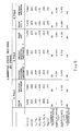
- Fig. 7 is a table showing preferred ranges and specific values of physical relationships and ratios associated with the laminations of Figs. 3 and 5 when dimensioned for different frame sizes and designed for different number of poles;
- Fig. 8 is a table showing comparative data for physical relationships and ratios associated with the laminations of Figs 3 and 5 (when of a NEMA 180 Frame size and designed for 2 (two), 4 (four), and 6 (six) pole operation) in relation to those of known laminations for a certain machine frame size;
- Fig. 9 is a table showing comparative data on physical relationships and ratios associated with the laminations of Figs. 3 and 5 (when of a NEMA 210 Frame size and designed for 2 (two) or 4 (four) pole operation) in relation to those of the known laminations for another machine frame size.
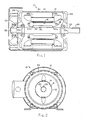
- Fig. 1 shows a side view, in section, of a dynamo electric machine 10 in which the present invention may be embodied.
- a front view of the machine 10 is shown in Fig. 2.
- the machine 10 includes a generally cylindrical outer casing 12, and a generally cylindrical stator 14 fixed coaxially within the outer casing 12 and having a coaxial stator bore 16.
- a rotor 18 is supported by suitable bearings 20a, 20b at the front and back of casing 12, to extend axially within the stator bore 16 and for rotational movement about the bore axis.
- a shaft part 22 of the rotor 18 extends axially from a front end shield 24 of the machine 10, and has a key 26 projecting radially outward from a recess cut axially a certain distance from the front of the shaft part 22. Key 26 serves to lock the shaft part 22 into a corresponding key way cut in a load member (not shown), e.g., a fan, to which rotational motive power is to be supplied by the machine 10.
- a load member not shown
- a back end shield 28 (Fig. 1) together with the casing 12 and the front end shield 24 serve to contain and protect the stator 14, rotor 18 and associated conductive windings.
- a machine cooling fan 30 is mounted on a rotor stub part 32 which extends outside the back end shield 28, and directs an air current flow over the casing.
- the stator 14 is comprised of a stack of plate laminations 34 of ferromagnetic material.
- the laminations 34 are stacked face-to-face and are held together to form a core by any of the various means well known in the art.
- a number S1 of slots extend along the axial length of the stator 14, and extend radially from the stator bore 16. These slots accommodate stator windings that have end turns 36, parts of which are shown in Fig. 1. Details of individual plate laminations embodying the invention in preferred forms are given below.
- the shaft 22 of the rotor 18 extends axially from the machine casing or housing 12 and has a stack of rotor laminations 40 fixed coaxially on the shaft 22 intermediate the front and back bearings 20a, 20b.
- Sets of conductive bars 42 pass through a number S2 of axially extending slots formed in the rotor 18 near the outer periphery of each of the laminations 40.
- the bars 42 are shorted to one another at the axial ends 44a, 44b of the stator of the laminations 40 by a set of end rings.
- stator winding end turns 36 at axial end faces 48a, 48b, of the stator 14 are a source of stator flux leakage i.e. magnetic flux produced by the stator winding which does not interface with the conductive bars 42 in the rotor laminations 40.
- stator flux leakage does not contribute to the resultant torque exerted on the rotor 18 when the stator winding or windings are energized, such flux leakage adversely effects the operating efficiency of the machine 10. It will therefore be understood that any means by which potential sources of stator flux leakage can be reduced or eliminated, are of great importance in dynamo-electric machine construction.
- the present invention aims to provide a dynamo-electric machine construction which conforms with industry standards, particularly with respect to the so-called 180 and 210 frame size constructions. It will be understood, however, that although dimensions for machine laminations disclosed herein will apply to the 180 and 210 frame sizes, the invention can be embodied with advantage in machines of various sizes and proportions.
- a stator plate lamination 34 comprises a flat annular plate of ferromagnetic material having an outer diameter "OD" according to the tabular values of Figs. 8 or 9 and a generally circular bore opening 50 of a certain inner diameter "ID".
- the plate 34 has a number S1 of equally circumferentially spaced slot openings 52 extending radially from an intermediate circumference 54 to form a number S1 of teeth 56 which extend radially to the circumference of the bore opening 50.
- the bore has a diameter of "ID”.
- the lamination 34 is a stator lamination so that the circumference of the bore opening 50 defines one boundary for a stator-rotor air gap and a bore for receiving the rotor.
- the slot openings 52 are formed to contain one or more stator windings which extend axially through the stator 14 when like ones of the plates 34 are stacked face-to-face with corresponding slot openings 52 substantially aligned with one another.
- the stator windings are arranged to correspond to an n (e.g., 2, 4, 6, etc.) pole operating configuration for the machine 10.
- n e.g., 2, 4, 6, etc.
- the annular plate 34 in Fig. 3 includes a tooth portion 58 defined by the teeth 56 between the intermediate circumference 54 and the air gap periphery.
- the remainder of the plate 34 is continuous between the intermediate circumference 54 and the outer periphery 59 to define a yoke portion 60 of the plate 34.
- Fig. 4 is an enlarged view of a part of the plate laminations 34 in Fig. 3. Specifically, a single slot opening 52 is shown surrounded by adjacent teeth 56. Lip parts 60 project circumferentially toward one another from the adjacent teeth 56, to define a mouth 62 (of width W10) of the slot opening 52. As is known, mouth 62 should be sufficiently wide to allow individual conductors 64 forming the stator winding to be inserted in the opening 52 through the mouth 62 when the machine 10 is assembled. The lip parts 60 act to seat a winding closure wedge 66 which holds the conductors 64 of the stator winding firmly in place within the stator slots formed by the openings 52.
- an insulating winding separator 68 may be positioned as shown in Fig. 4 in the stator slots, and an insulating film 70 positioned against the walls of the stator slots prevents arcing or short circuiting of individual conductors 64 with the material of which the laminations 34 are made.
- the teeth 56 are sufficiently wide relative to the area of the slot openings 52 so that the ratio of flux density in the tooth portion 58 (BT1) to flux density in the yoke portion 60 (BY1) when the stator windings are energized, is substantially optimized for a given n pole operation of the stator windings.
- the actual number S1 of slot openings is not critical.
- the lamination plate 34 in Fig. 3 is shown with 24 slots and has relative dimensions suitable for incorporation in a 180 frame size machine.
- a lamination plate 32 ⁇ according to the invention as shown in Fig. 5, has 36 slots and relative dimensions suitable for use in a 210 frame size machine. Parts of the plate lamination 34 ⁇ which correspond to those of the lamination 34 in Figs. 3 and 4, are indentified with similar reference numerals.
- An underlying concept of the present invention is to utilize maximum amounts of ferromagnetic material (e.g., iron) for the laminations 34 (or 34 ⁇ ) and minimum amounts of winding conductors, e.g., the individual conductors 64 or 64 ⁇ in a dynamo-electric machine having a desired power handling capability.
- ferromagnetic material e.g., iron
- the lip parts 61 thus become very small relative to the known structures as a consequence of the relatively wide teeth 56.
- Use of less winding material also results in smaller end turns (e.g., the stator end turns 36) at the end faces of the lamination stack, and, thus, undesired flux leakage is significantly reduced from that in the prior constructions.
- Fig. 7 is a table which shows preferred ranges and specific values for physical constants, relationships, and ratios associated with both stator and rotor laminations having a number of slots S2 according to the invention. Assuming, e.g., that a machine conforming to a standard frame size is to be constructed, the NEMA Standards will limit the maximum outside dimensions of the motor in which the stator lamination size is optimized. Typical outer diameters (O.D.) for both stator and rotor laminations for use in the 180 and 210 frame size standard, are represented in Fig. 7. Fig. 7 also provides specific values as well as ranges for various ratios which are used to define the improved stator lamination.
- O.D. outer diameters
- the ratio ID/OD represents the ratio of the inner diameter of the stator lamination to the outer diameter and gives an indication of the larger amount of ferromagnetic material than copper which is used in the present laminations.
- the value Bt1/By1 can be used to represent the flux density in the tooth to the flux density in the yoke if it is assumed that the flux in the tooth and yoke is the same, which is a close approximation. This ratio gives an indication of tooth to yoke ratio.
- the final column in Fig. 7 is a ratio of the interaction of the stator to the rotor, where S represents the number of slots, T represents the width of the tooth, 1 represents the stator and 2 represents the rotor.
- the chart of Fig. 7 sets forth the values and ranges for 2, 4 and 6 pole machines (n). For the 4 pole, 180 frame and 210 frame, two embodiments are shown.
- Fig. 8 is a table in which physical constants, relationships, and ratios associated with the laminations dimensioned according to the invention as shown in Fig. 7 are compared with the closest known prior configuration, for 2, 4 and 6 pole AC induction motors for a 180 frame size. For comparison with known values, the specific measurements have been converted into inches. Of course, the ranges still remain the same as was shown in Fig. 7. Included in this chart is a value of the net and gross area of the slots in the stator multiplied by the number of slots in the stator (S1). The net slot area (ASLOT-NET) equals the gross slot area (ASLOT-GROSS, see Fig. 3) less the area occupied by the slot liners, separators, and wedges and less the area A3 at the mouth not available for insertion of windings (see Fig. 4).
- Fig. 9 is a table similar to that of Fig. 8, in which laminations configured according to the invention as shown in Fig. 7, are compared with the closest known prior laminations for two and four pole AC induction motors with a 210 frame size. Again specific values have been converted to inches.
- Machines employing laminations configured according to the invention have yielded greater horsepower to volume ratios when compared with known corresponding machines.
- variations occur depending on efficiency.
- Tables 1, 2 and 3 below show a comparison for equal efficiency shown and volume measurements for 2, 4 and 6 pole AC induction motors with laminations according to the present invention and corresponding motors according to the prior art.
- Fig. 10 illustrates a rotor lamination, more fully described in the incorporated by reference application S. N. 020,299 03 GP 6073.
- Fig. 10 clearly illustrates the width T2 of the rotor teeth, and it will be understood that a fabricated rotor as shown in Fig. 1 would include a number S2 of rotor slots, and the same number S2 of rotor teeth each having a width T2 such that the various ratios involving S2 and T2, or the value of S2 in the tables of Figs. 7, 8 and 9 are determinable in motors wherein principles of the present invention are applied.
- Terminology used herein includes the words “generally cylindrical”, “essentially round” and “annular”. When these terms are used herein with reference to or in connection with laminations (or plates) or structures made from such laminations (e.g., “cores”, stators, etc.), such terms will be inclusively descriptive of laminations, cores, etc. that do not have “true round” configurations due to the presence of peripherally located "key slots", marker notches, flats resulting from producltion processes (such as occur from zig-zag punch lines, for example), and so forth.
Abstract
Description
- The present invention relates generally to core laminations or punchings for use in dynamo-electric machines, and more particularly to a lamination construction in which teeth and yoke portions of the laminations have relative dimensions such as to provide improved output for a given size machine.
- Arrangements are known for improving the efficiency or power output of dynamo-electric machines through the provision of certain slot distributions in either a stator or rotor core element of the machine, e.g. U.S. Patent 4,566,179 (January 28, 1986) or by creating a prescribed variation of magnetic flux through a pole of the machine stator relative to the ampere-turns of the pole such as in U.S. Patent 4,209, 720 (June 24, 1980). However, there has not been disclosed a machine lamination construction by which the operating efficiency of a dynamo-electric machine having a stacked laminated stator and/or rotor is improved by a prescribed ratio of inner diameter to outer diameter for the lamination. Also, there has been no disclosure of a lamination construction by which the ratio of flux density in a tooth portion of the lamination to flux density in a yoke portion of the lamination can be increased over that obtained conventionally, and, as a result, yield greater output or operating efficiency for the machine.
- An object of the invention is to provide a dynamo-electric machine lamination construction in which improvement is obtained through a greater amount of lamination material and less winding conductors than used previously.
- Another object of the invention is to provide a dynamo-electric machine in which leakage flux from end turns of a winding enbedded in slots of a laminated core, is substantially reduced.
- A further object of the invention is to provide a dynamo-electric machine having a greater horsepower to volume ratio than that previously obtained.
- The various features of novelty which characterize the invention are pointed out with particularity in the claims annexed to and forming a part of the present disclosure. For a better understanding of the invention, its operating advantages and specific objects attained by its use, reference should be had to the accompanying drawing and descriptive matter in which there are illustrated and described preferred embodiments of the invention.
- In the drawing:
- Fig. 1 is a side view, partly in section, of a dynamo-electric machine in which the present invention may be embodied; Fig. 2 is a front view of the machine in Fig. 2; Fig. 3 is a plan view of a plate lamination for forming a stator in the machine of Figs. 1 and 2; Fig. 4 is an enlarged view of a part of the lamination in Fig. 3; Fig. 5 is a plan view of another plate lamination for forming a stator in the machine of Figs. 1 and 2; Fig. 6 is an enlarged view of a part of the lamination in Fig. 5; Fig. 7 is a table showing preferred ranges and specific values of physical relationships and ratios associated with the laminations of Figs. 3 and 5 when dimensioned for different frame sizes and designed for different number of poles; Fig. 8 is a table showing comparative data for physical relationships and ratios associated with the laminations of Figs 3 and 5 (when of a NEMA 180 Frame size and designed for 2 (two), 4 (four), and 6 (six) pole operation) in relation to those of known laminations for a certain machine frame size; and Fig. 9 is a table showing comparative data on physical relationships and ratios associated with the laminations of Figs. 3 and 5 (when of a NEMA 210 Frame size and designed for 2 (two) or 4 (four) pole operation) in relation to those of the known laminations for another machine frame size.
- Fig. 1 shows a side view, in section, of a dynamo
electric machine 10 in which the present invention may be embodied. A front view of themachine 10 is shown in Fig. 2. - Basically, the
machine 10 includes a generally cylindricalouter casing 12, and a generallycylindrical stator 14 fixed coaxially within theouter casing 12 and having acoaxial stator bore 16. Arotor 18 is supported by suitable bearings 20a, 20b at the front and back ofcasing 12, to extend axially within thestator bore 16 and for rotational movement about the bore axis. In the particular example shown ashaft part 22 of therotor 18 extends axially from afront end shield 24 of themachine 10, and has a key 26 projecting radially outward from a recess cut axially a certain distance from the front of theshaft part 22.Key 26 serves to lock theshaft part 22 into a corresponding key way cut in a load member (not shown), e.g., a fan, to which rotational motive power is to be supplied by themachine 10. - A back end shield 28 (Fig. 1) together with the
casing 12 and thefront end shield 24 serve to contain and protect thestator 14,rotor 18 and associated conductive windings. In the example shown, amachine cooling fan 30 is mounted on arotor stub part 32 which extends outside theback end shield 28, and directs an air current flow over the casing. - As shown in Fig. 1, the
stator 14 is comprised of a stack ofplate laminations 34 of ferromagnetic material. Thelaminations 34 are stacked face-to-face and are held together to form a core by any of the various means well known in the art. A number S₁ of slots extend along the axial length of thestator 14, and extend radially from thestator bore 16. These slots accommodate stator windings that have end turns 36, parts of which are shown in Fig. 1. Details of individual plate laminations embodying the invention in preferred forms are given below. - As shown in Fig. 1, the
shaft 22 of therotor 18 extends axially from the machine casing orhousing 12 and has a stack ofrotor laminations 40 fixed coaxially on theshaft 22 intermediate the front and back bearings 20a, 20b. Sets ofconductive bars 42 pass through a number S₂ of axially extending slots formed in therotor 18 near the outer periphery of each of thelaminations 40. Thebars 42 are shorted to one another at theaxial ends 44a, 44b of the stator of thelaminations 40 by a set of end rings. - In Fig. 1, the stator winding end turns 36 at
axial end faces stator 14, are a source of stator flux leakage i.e. magnetic flux produced by the stator winding which does not interface with theconductive bars 42 in therotor laminations 40. Inasmuch as stator flux leakage does not contribute to the resultant torque exerted on therotor 18 when the stator winding or windings are energized, such flux leakage adversely effects the operating efficiency of themachine 10. It will therefore be understood that any means by which potential sources of stator flux leakage can be reduced or eliminated, are of great importance in dynamo-electric machine construction. - Certain machine construction standards are known in the industry, particularly those set out by ANSI/NEMA Standards Publication No. MG1-1978(R1981). The entire contents of the cited publication are incorporated by reference herein.
- The present invention aims to provide a dynamo-electric machine construction which conforms with industry standards, particularly with respect to the so-called 180 and 210 frame size constructions. It will be understood, however, that although dimensions for machine laminations disclosed herein will apply to the 180 and 210 frame sizes, the invention can be embodied with advantage in machines of various sizes and proportions.
- In Fig. 3, a
stator plate lamination 34 according to the invention comprises a flat annular plate of ferromagnetic material having an outer diameter "OD" according to the tabular values of Figs. 8 or 9 and a generally circular bore opening 50 of a certain inner diameter "ID". Theplate 34 has a number S₁ of equally circumferentially spacedslot openings 52 extending radially from anintermediate circumference 54 to form a number S₁ ofteeth 56 which extend radially to the circumference of the bore opening 50. The bore has a diameter of "ID". In the illustrated embodiment in Fig. 3, thelamination 34 is a stator lamination so that the circumference of thebore opening 50 defines one boundary for a stator-rotor air gap and a bore for receiving the rotor. - The
slot openings 52 are formed to contain one or more stator windings which extend axially through thestator 14 when like ones of theplates 34 are stacked face-to-face withcorresponding slot openings 52 substantially aligned with one another. In the assembledmachine 10 of Figs. 1 and 2, the stator windings are arranged to correspond to an n (e.g., 2, 4, 6, etc.) pole operating configuration for themachine 10. When the stator windings are connected to an outside electrical source, magnetic flux is produced next to the substantially aligned air gap peripheries of the stackedlaminations 34 to interact with theconductive bars 42 of therotor 18. - The
annular plate 34 in Fig. 3 includes atooth portion 58 defined by theteeth 56 between theintermediate circumference 54 and the air gap periphery. The remainder of theplate 34 is continuous between theintermediate circumference 54 and theouter periphery 59 to define ayoke portion 60 of theplate 34. - Fig. 4 is an enlarged view of a part of the
plate laminations 34 in Fig. 3. Specifically, asingle slot opening 52 is shown surrounded byadjacent teeth 56.Lip parts 60 project circumferentially toward one another from theadjacent teeth 56, to define a mouth 62 (of width W₁₀) of the slot opening 52. As is known,mouth 62 should be sufficiently wide to allowindividual conductors 64 forming the stator winding to be inserted in theopening 52 through themouth 62 when themachine 10 is assembled. Thelip parts 60 act to seat awinding closure wedge 66 which holds theconductors 64 of the stator winding firmly in place within the stator slots formed by theopenings 52. To separate individual stator windings, aninsulating winding separator 68 may be positioned as shown in Fig. 4 in the stator slots, and aninsulating film 70 positioned against the walls of the stator slots prevents arcing or short circuiting ofindividual conductors 64 with the material of which thelaminations 34 are made. - According to the invention, for a given ratio of inner diameter ID to outer diameter OD of the
plate 34, theteeth 56 are sufficiently wide relative to the area of theslot openings 52 so that the ratio of flux density in the tooth portion 58 (BT₁) to flux density in the yoke portion 60 (BY₁) when the stator windings are energized, is substantially optimized for a given n pole operation of the stator windings. The actual number S₁ of slot openings is not critical. For example, thelamination plate 34 in Fig. 3 is shown with 24 slots and has relative dimensions suitable for incorporation in a 180 frame size machine. A lamination plate 32ʹ according to the invention as shown in Fig. 5, has 36 slots and relative dimensions suitable for use in a 210 frame size machine. Parts of the plate lamination 34ʹ which correspond to those of thelamination 34 in Figs. 3 and 4, are indentified with similar reference numerals. - An underlying concept of the present invention is to utilize maximum amounts of ferromagnetic material (e.g., iron) for the laminations 34 (or 34ʹ) and minimum amounts of winding conductors, e.g., the
individual conductors 64 or 64ʹ in a dynamo-electric machine having a desired power handling capability. - In the disclosed embodiments, the ratios of the
tooth portions 58 to yokeportions 60 for thelaminations 34 substantially differ from known constructions, as does the ratio of inner diameter to outer diameter of thelaminations 34. Thelip parts 61 thus become very small relative to the known structures as a consequence of the relativelywide teeth 56. Use of less winding material also results in smaller end turns (e.g., the stator end turns 36) at the end faces of the lamination stack, and, thus, undesired flux leakage is significantly reduced from that in the prior constructions. - Fig. 7 is a table which shows preferred ranges and specific values for physical constants, relationships, and ratios associated with both stator and rotor laminations having a number of slots S₂ according to the invention. Assuming, e.g., that a machine conforming to a standard frame size is to be constructed, the NEMA Standards will limit the maximum outside dimensions of the motor in which the stator lamination size is optimized. Typical outer diameters (O.D.) for both stator and rotor laminations for use in the 180 and 210 frame size standard, are represented in Fig. 7. Fig. 7 also provides specific values as well as ranges for various ratios which are used to define the improved stator lamination. The ratio ID/OD represents the ratio of the inner diameter of the stator lamination to the outer diameter and gives an indication of the larger amount of ferromagnetic material than copper which is used in the present laminations. The ratio T1/Ts represents a ratio of the tooth width (T₁) of the stator lamination to the bore circumference divided by the number of stator slots S₁, (TS = π x ID/S₁). This effectively provides an indication of the tooth width. The value Bt1/By1 can be used to represent the flux density in the tooth to the flux density in the yoke if it is assumed that the flux in the tooth and yoke is the same, which is a close approximation. This ratio gives an indication of tooth to yoke ratio. This ratio is also determinable geometrically from a stator lamination by the relationship Bt1/By1 = π x n x Y1)/(S₁ x T₁) where n is the number of poles, Y1 is the dimension shown in Figs. 3 and 5, and S₁ and T₁ are as defined hereinabove.
- The final column in Fig. 7 is a ratio of the interaction of the stator to the rotor, where S represents the number of slots, T represents the width of the tooth, 1 represents the stator and 2 represents the rotor. The chart of Fig. 7 sets forth the values and ranges for 2, 4 and 6 pole machines (n). For the 4 pole, 180 frame and 210 frame, two embodiments are shown.
- Fig. 8 is a table in which physical constants, relationships, and ratios associated with the laminations dimensioned according to the invention as shown in Fig. 7 are compared with the closest known prior configuration, for 2, 4 and 6 pole AC induction motors for a 180 frame size. For comparison with known values, the specific measurements have been converted into inches. Of course, the ranges still remain the same as was shown in Fig. 7. Included in this chart is a value of the net and gross area of the slots in the stator multiplied by the number of slots in the stator (S1). The net slot area (ASLOT-NET) equals the gross slot area (ASLOT-GROSS, see Fig. 3) less the area occupied by the slot liners, separators, and wedges and less the area A3 at the mouth not available for insertion of windings (see Fig. 4).
- Fig. 9 is a table similar to that of Fig. 8, in which laminations configured according to the invention as shown in Fig. 7, are compared with the closest known prior laminations for two and four pole AC induction motors with a 210 frame size. Again specific values have been converted to inches.
- It will be seen from Figs. 8 and 9 that in addition to having a lower inner diameter to outer diameter ratio and a higher ratio of flux density between the tooth and yoke portions than in the prior corresponding laminations, the teeth width of the present laminations is generally greater in the present laminations. It should be remembered that the resulting improved laminations are the result of an interaction of the various values. Thus, not each and every one of the values is consistently changed for each embodiment. The result, however, is consonant with the underlying concept of the present invention which, as mentioned, is to utilize maximum amounts of lamination material and minimum amounts of winding (i.e., copper) material.
- Machines employing laminations configured according to the invention have yielded greater horsepower to volume ratios when compared with known corresponding machines. Of course, variations occur depending on efficiency. However, Tables 1, 2 and 3 below show a comparison for equal efficiency shown and volume measurements for 2, 4 and 6 pole AC induction motors with laminations according to the present invention and corresponding motors according to the prior art.
- Through the use of relatively wider teeth in the present laminations, flux density satauration for a given size and power machine can be achieved with a shorter lamination stack than in the prior constructions. Hence, the electromagnetic volume (OD)²L for machines according to the invention is generally lower than the volumes in the prior machines for the same efficiency. The use of wider or fatter teeth also produces a relatively high flux density in the air gap between stator and rotor lamination stacks in machines according to the invention. Thus, more torque is produced on the rotor for a given machine size.
- Fig. 10 illustrates a rotor lamination, more fully described in the incorporated by reference application S. N. 020,299 03 GP 6073. Fig. 10 clearly illustrates the width T2 of the rotor teeth, and it will be understood that a fabricated rotor as shown in Fig. 1 would include a number S2 of rotor slots, and the same number S2 of rotor teeth each having a width T2 such that the various ratios involving S2 and T2, or the value of S2 in the tables of Figs. 7, 8 and 9 are determinable in motors wherein principles of the present invention are applied.

- Terminology used herein includes the words "generally cylindrical", "essentially round" and "annular". When these terms are used herein with reference to or in connection with laminations (or plates) or structures made from such laminations (e.g., "cores", stators, etc.), such terms will be inclusively descriptive of laminations, cores, etc. that do not have "true round" configurations due to the presence of peripherally located "key slots", marker notches, flats resulting from producltion processes (such as occur from zig-zag punch lines, for example), and so forth.
- This application 03 GP 6082 is being filed on the same day as commonly assigned applications 03 GP 6077 - BASE ASSEMBLY FOR DYNAMO-ELECTRIC MACHINE in the name of Robert L. Sieber, S. N. 019,823; 03 GP 6073 - CLOSED SLOT ROTOR CONSTRUCTION in the names of Deepakkumar J. Gandhi et al., S. N. 020,299; and 03 GP 6093 - LIP STRUCTURE FOR A STATOR IN A DYNAMO-ELECTRIC MACHINE in the names of Deepakkumar J. Gandhi et al., S. N. 019,811. The entire disclosures of all of these three (3) other applications are specifically incorporated herein by reference.
- While the concept of the invention has generally been described in connection with a stator lamination, it should be appreciated that the same concept of increasing the amount of ferromagnetic material as compared to the amount of copper, or conductive material, can also be applied to a rotor lamination. Similar concepts would be applied by making the teeth wider on the rotor and the slots smaller.
- While the foregoing description represents preferred embodiments of the present invention, it will be obvious to those skilled in the art that various changes and modifications may be made, without departing from the true spirit and scope of the present invention.
Claims (34)
a flat annular plate of ferromagnetic material having a given outer diameter and a generally circular bore opening of a certain inner diameter,
said plate having a number of equally circumferentially spaced slot openings extending radially from an intermediate circumference of said plate to form a number of teeth which extend radially to an air gap periphery of said plate,
wherein said slot openings are formed to contain electrically conducting elements which extend axially through the lamination stack when like ones of said plate are stacked face to face with corresponding slot openings substantially aligned with one another, said conducting elements being arranged to correspond to an n pole operating configuration, and magnetic flux is produced next to the inner peripheries of the stacked plates when electric current is passed through the conducting elements,
said annular plate including a tooth portion defined by said teeth between said intermediate circumference and said inner periphery, and a yoke portion defined by a substantially continuous surface of said plate between said intermediate circumference and the outer periphery of said plate radially opposite said inner periphery, and
wherein for a given ratio of said certain inner diameter to said given outer diameter for said plate, said teeth are sufficiently wide relative to the area of said slot openings so that the ratio of flux density in said tooth portion to flux density in said yoke portion in response to said electric current is optimized for a given n pole operating configuration.
a generally cylindrical casing;
a stator core fixed in said casing and comprised of plate laminations of ferromagnetic material, said stator core having a cylindrical bore;
a stator winding embedded in slots a certain radial depth from the circumference of said bore and which slots extend generally axially along the core, with end turns of said winding extending beyond end faces of said stator core;
a rotor supported in said bore for rotational movement, said rotor including conductive means for interacting with a magnetic field produced in an air gap between the outer periphery of said rotor and the inner periphery of the bore of said stator core when said stator winding is energized;
wherein each of said stator plate laminations comprises:
a flat annular plate of ferromagnetic material having a preselected outer diameter and a generally circular inner opening of a preselected inner diameter which forms the stator bore when like ones of said plates are stacked face-to-face with one another,
said plate having a number of uniformly circumferentially spaced slots which extend radially outwardly from the bore to an intermediate circumference of said plate and which establish teeth therebetween, the distal ends of said teeth establish said bore, said slot openings forming said stator slots when corresponding slot openings in the like plates are aligned with one another and the plates are stacked,
said annular plate including a tooth portion defined by said teeth between said intermediate circumference and said bore, and a yoke portion defined between said intermediate circumference and the outer periphery of said plate, and
wherein for a given ratio of said preselected inner diameter to said preselected outer diameter for said plate, said teeth are sufficiently wide relative to the area of said slot openings so that the ratio of flux density in said tooth portion to flux density in said yoke portion in response to energization of the winding is optimized for a given n pole operating configuration of said stator winding.
a flat annular plate of ferromagnetic material having a given outer diameter and a generally circular bore opening of a certain inner diameter,
each plate having a number of uniformly circumferentially spaced slot openings extending radially from an intermediate circumference of said plate to form a number of teeth which extend radially to an air gap periphery of said plate,
wherein said slot openings are formed to contain electrically conducting elements which extend axially through the lamination stack when like ones of the plates are stacked face-to-face with corresponding slot openings in communication with one another, said conducting elements being arranged to correspond to an n pole operating configuration, and magnetic flux is produced around the conducting elements when electric current is passed through the conducting elements,
said annular plate including a tooth portion defined by said teeth between said intermediate circumference and said inner periphery, and a yoke portion defined by a substantially continuous surface of said plate between said intermediate circumference and the outer periphery of said plate radially opposite said inner periphery, and
wherein the product of the number of rotor slots times the rotor tooth width is a first value, the product of the number of stator slots times the width of the stator teeth is a second value, and the ratio of the first value to the second value is in the range of .83 to .88 when n is 2 and greater than .82 when n is 6.
a flat annular essentially full round plate of ferromagnetic material having an outer diameter of about 203 mm. and a generally circular bore opening of a preselected inner diameter,
each plate having a number of uniformly circumferentially spaced slot openings extending radially from an intermediate circumference of said plate to form a number of teeth which extend radially to an air gap periphery of said plate,
wherein said slot openings are formed to contain electrically conducting elements which extend axially through the lamination stack when like ones of the plates are stacked face-to-face with corresponding slot openings in communication with one another, said conducting elements being arranged to correspond to an n pole operating configuration, and magnetic flux is produced around the conducting elements when electric current is passed through the conducting elements,
said annular plate including a tooth portion defined by said teeth between said intermediate circumference and said inner periphery, and a yoke portion defined by a substantially continuous surface of said plate between said intermediate circumference and the outer periphery of said plate radially opposite said inner periphery, and
wherein n is preselected to be less than 6, the ratio of flux density in said tooth portion to flux density in said yoke portion is greater than 1.17, the product of the number of rotor slots times the rotor tooth width is a first value, the product of the number of stator slots times the width of the stator teeth is a second value, and the ratio of the first value to the second value is in the range of .83 to .93.
Applications Claiming Priority (2)
| Application Number | Priority Date | Filing Date | Title |
|---|---|---|---|
| US07/020,297 US4780635A (en) | 1987-02-27 | 1987-02-27 | Dynamo-electric machine lamination construction |
| US20297 | 1987-02-27 |
Publications (3)
| Publication Number | Publication Date |
|---|---|
| EP0280194A2 true EP0280194A2 (en) | 1988-08-31 |
| EP0280194A3 EP0280194A3 (en) | 1990-01-17 |
| EP0280194B1 EP0280194B1 (en) | 1995-01-04 |
Family
ID=21797820
Family Applications (1)
| Application Number | Title | Priority Date | Filing Date |
|---|---|---|---|
| EP88102369A Expired - Lifetime EP0280194B1 (en) | 1987-02-27 | 1988-02-18 | Dynamo-electric machine lamination construction |
Country Status (5)
| Country | Link |
|---|---|
| US (1) | US4780635A (en) |
| EP (1) | EP0280194B1 (en) |
| JP (1) | JPS63234849A (en) |
| KR (1) | KR0139002B1 (en) |
| DE (1) | DE3852658T2 (en) |
Cited By (5)
| Publication number | Priority date | Publication date | Assignee | Title |
|---|---|---|---|---|
| WO2010066609A2 (en) * | 2008-12-08 | 2010-06-17 | Robert Bosch Gmbh | Electric machine having a claw-pole rotor |
| EP2202871A3 (en) * | 2008-12-29 | 2014-04-09 | Tesla Motors, Inc. | Induction motor with improved torque density |
| WO2014090440A3 (en) * | 2012-12-10 | 2015-04-23 | Robert Bosch Gmbh | Asynchronous machine with optimized distribution of electrical losses between stator and rotor |
| CN107659008A (en) * | 2017-11-13 | 2018-02-02 | 安徽美芝精密制造有限公司 | Electric machine assembly, compressor and the refrigeration plant of compressor |
| WO2018024606A1 (en) * | 2016-08-05 | 2018-02-08 | Volabo Gmbh | Electric machine |
Families Citing this family (27)
| Publication number | Priority date | Publication date | Assignee | Title |
|---|---|---|---|---|
| US4801832A (en) * | 1987-11-04 | 1989-01-31 | General Electric Company | Stator and rotor lamination construction for a dynamo-electric machine |
| US5744888A (en) * | 1995-02-03 | 1998-04-28 | Tiedtke-Buhling-Kinne & Partner | Multiphase and multipole electrical machine |
| DE69526244T2 (en) * | 1995-04-19 | 2002-08-22 | Shigeaki Hayasaka | INDUCTION GENERATOR WITH A SINGLE PAIR OF OPPOSITE MAGNETIC POLES |
| US6304018B1 (en) | 1995-11-21 | 2001-10-16 | Valeo Electrical Systems, Inc. | Externally-wound stator with improved magnetic transition |
| US5829305A (en) * | 1996-03-18 | 1998-11-03 | Itt Automotive Electrical Systems, Inc. | Vehicle window drive system and method |
| US6202285B1 (en) | 1998-01-16 | 2001-03-20 | Reliance Electric Technologies, Llc | Electric motor having electrostatic shield arrangement |
| US5979087A (en) * | 1998-01-16 | 1999-11-09 | Reliance Electric Industrial Company | Electric motor having electrostatic shield arrangement |
| US6011338A (en) * | 1998-07-10 | 2000-01-04 | Reliance Electric Industrial Company | Electric motor having auxiliary winding arrangement for electrostatic shielding |
| KR20000056038A (en) * | 1999-02-12 | 2000-09-15 | 에릭 발리베 | Rotor of start motor |
| US6758430B1 (en) * | 1999-02-16 | 2004-07-06 | Aesop, Inc. | Method of winding motors and other electric machines to reduce AC losses |
| US6313559B1 (en) * | 1999-04-14 | 2001-11-06 | Denso Corporation | Stator arrangement of rotary electric machine |
| JP3980402B2 (en) * | 2002-05-13 | 2007-09-26 | 本田技研工業株式会社 | Rotating electric machine |
| US20040012291A1 (en) * | 2002-07-19 | 2004-01-22 | Mclennan Paul S. | High density winding for electric motor |
| DE20308665U1 (en) * | 2003-06-03 | 2004-12-30 | Minebea Co., Ltd. | Internal rotor electric motor |
| KR100629869B1 (en) * | 2004-05-25 | 2006-09-29 | 엘지전자 주식회사 | Rotor slot structure of universal motor |
| DE102006016249A1 (en) * | 2006-03-31 | 2007-10-04 | Robert Bosch Gmbh | Stator for electrical machine, has grooves separated from each other by tooth, where ratio of mass of wires in groove to total mass of wire lies between specified values and groove slot width is equal to groove width |
| US7709992B2 (en) * | 2008-07-31 | 2010-05-04 | Emerson Electric Co. | Electric machine |
| JP5424814B2 (en) * | 2009-05-21 | 2014-02-26 | 三菱電機株式会社 | Permanent magnet type rotating electric machine |
| US20110109188A1 (en) * | 2009-11-10 | 2011-05-12 | Shaver Clark D | Partial Discharge Resistant Motor Slot Insulation |
| CN202889143U (en) * | 2011-12-28 | 2013-04-17 | 日本电产株式会社 | Single-phase induction motor |
| DE102015201731A1 (en) * | 2014-11-13 | 2016-05-19 | Robert Bosch Gmbh | Electric machine |
| DE112015006992T5 (en) * | 2015-10-01 | 2018-07-05 | Mitsubishi Electric Corporation | Three-phase induction motor |
| CN106300850A (en) * | 2016-10-26 | 2017-01-04 | 北京明正维元电机技术有限公司 | A kind of permagnetic synchronous motor 175 stator punching |
| WO2019073509A1 (en) * | 2017-10-10 | 2019-04-18 | 三菱電機株式会社 | Stator, electric motor, compressor, air conditioning device, and stator manufacturing method |
| DE102019127072A1 (en) * | 2019-10-09 | 2021-04-15 | Bayerische Motoren Werke Aktiengesellschaft | Efficient asynchronous machine for electric vehicles |
| DE102020128431A1 (en) | 2020-10-29 | 2022-05-05 | Dr. Ing. H.C. F. Porsche Aktiengesellschaft | Traction motor for a vehicle |
| DE102020129528A1 (en) | 2020-11-10 | 2022-05-12 | Dr. Ing. H.C. F. Porsche Aktiengesellschaft | Electrical machine for a vehicle |
Citations (3)
| Publication number | Priority date | Publication date | Assignee | Title |
|---|---|---|---|---|
| US3235762A (en) * | 1962-05-02 | 1966-02-15 | Gen Electric | Stator for use in alternating current induction motors |
| GB2020914A (en) * | 1978-05-10 | 1979-11-21 | Gen Electric | Laminated stators for dynamo-electric machines |
| JPS6039352A (en) * | 1983-08-12 | 1985-03-01 | Hitachi Ltd | Core for small-sized capacitor induction motor |
Family Cites Families (11)
| Publication number | Priority date | Publication date | Assignee | Title |
|---|---|---|---|---|
| US3081412A (en) * | 1958-10-23 | 1963-03-12 | Laborde & Kupfer | Alternator armature teeth |
| US3159762A (en) * | 1958-12-30 | 1964-12-01 | Franklin Electric Co Inc | Core construction |
| US3229134A (en) * | 1962-01-25 | 1966-01-11 | Litton Industries Inc | Thermal variation compensation means and method |
| US3762041A (en) * | 1971-11-10 | 1973-10-02 | Gen Electric | Methods for manufacturing slotted core structures |
| JPS5260905A (en) * | 1975-11-14 | 1977-05-19 | Hitachi Ltd | Stator core |
| FR2414816A1 (en) * | 1978-01-11 | 1979-08-10 | Citroen Sa | IMPROVEMENTS TO ELECTRIC MOTORS SUPPLIED BY CHECK CURRENT |
| JPS5541168A (en) * | 1978-09-16 | 1980-03-22 | Shinko Electric Co Ltd | Rotary electric machine |
| JPS5849054A (en) * | 1981-09-16 | 1983-03-23 | Sanyo Electric Co Ltd | Stator core for motor |
| US4566179A (en) * | 1983-05-19 | 1986-01-28 | Display Components, Inc. | Core element for electrodynamic rotary machine |
| JPH0210780Y2 (en) * | 1984-12-18 | 1990-03-16 | ||
| US4654552A (en) * | 1985-03-28 | 1987-03-31 | General Electric Company | Lanced strip and edgewise wound core |
-
1987
- 1987-02-27 US US07/020,297 patent/US4780635A/en not_active Expired - Lifetime
-
1988
- 1988-02-18 EP EP88102369A patent/EP0280194B1/en not_active Expired - Lifetime
- 1988-02-18 DE DE3852658T patent/DE3852658T2/en not_active Expired - Fee Related
- 1988-02-26 JP JP63042412A patent/JPS63234849A/en active Pending
- 1988-02-27 KR KR1019880002036A patent/KR0139002B1/en not_active IP Right Cessation
Patent Citations (3)
| Publication number | Priority date | Publication date | Assignee | Title |
|---|---|---|---|---|
| US3235762A (en) * | 1962-05-02 | 1966-02-15 | Gen Electric | Stator for use in alternating current induction motors |
| GB2020914A (en) * | 1978-05-10 | 1979-11-21 | Gen Electric | Laminated stators for dynamo-electric machines |
| JPS6039352A (en) * | 1983-08-12 | 1985-03-01 | Hitachi Ltd | Core for small-sized capacitor induction motor |
Non-Patent Citations (1)
| Title |
|---|
| PATENT ABSTRACTS OF JAPAN vol. 009, no. 165 (E-327) <1888> 10 July 1985 & JP 60 039352 A (HITACHI SEISAKUSHO K.K.) 01 March 1985 * |
Cited By (13)
| Publication number | Priority date | Publication date | Assignee | Title |
|---|---|---|---|---|
| WO2010066609A2 (en) * | 2008-12-08 | 2010-06-17 | Robert Bosch Gmbh | Electric machine having a claw-pole rotor |
| WO2010066609A3 (en) * | 2008-12-08 | 2011-04-21 | Robert Bosch Gmbh | Electric machine having a claw-pole rotor |
| EP2202871A3 (en) * | 2008-12-29 | 2014-04-09 | Tesla Motors, Inc. | Induction motor with improved torque density |
| EP2202871B2 (en) † | 2008-12-29 | 2019-07-24 | Tesla, Inc. | Induction motor with improved torque density |
| EP2202871B1 (en) | 2008-12-29 | 2015-05-06 | Tesla Motors, Inc. | Induction motor with improved torque density |
| CN104854775B (en) * | 2012-12-10 | 2017-08-15 | 罗伯特·博世有限公司 | The asynchronous machine of electric loss most preferably between distribution stator and rotor |
| CN104854775A (en) * | 2012-12-10 | 2015-08-19 | 罗伯特·博世有限公司 | Asynchronous machine with optimized distribution of electrical losses between stator and rotor |
| US9973050B2 (en) | 2012-12-10 | 2018-05-15 | Robert Bosch Gmbh | Asynchronous machine with optimized distribution of electrical losses between stator and rotor |
| WO2014090440A3 (en) * | 2012-12-10 | 2015-04-23 | Robert Bosch Gmbh | Asynchronous machine with optimized distribution of electrical losses between stator and rotor |
| WO2018024606A1 (en) * | 2016-08-05 | 2018-02-08 | Volabo Gmbh | Electric machine |
| CN109891713A (en) * | 2016-08-05 | 2019-06-14 | 沃拉博股份有限公司 | Motor |
| US11095172B2 (en) | 2016-08-05 | 2021-08-17 | Molabo Gmbh | Electric machine |
| CN107659008A (en) * | 2017-11-13 | 2018-02-02 | 安徽美芝精密制造有限公司 | Electric machine assembly, compressor and the refrigeration plant of compressor |
Also Published As
| Publication number | Publication date |
|---|---|
| JPS63234849A (en) | 1988-09-30 |
| EP0280194A3 (en) | 1990-01-17 |
| KR0139002B1 (en) | 1998-06-15 |
| US4780635A (en) | 1988-10-25 |
| KR880010536A (en) | 1988-10-10 |
| DE3852658T2 (en) | 1995-08-10 |
| EP0280194B1 (en) | 1995-01-04 |
| DE3852658D1 (en) | 1995-02-16 |
Similar Documents
| Publication | Publication Date | Title |
|---|---|---|
| EP0280194B1 (en) | Dynamo-electric machine lamination construction | |
| EP0314860B1 (en) | Stator and rotor lamination construction for a dynamo-electric machine | |
| US4831301A (en) | Dynamo-electric machine lamination construction | |
| US7030528B2 (en) | Dual concentric AC motor | |
| EP0289292B1 (en) | Variable reluctance motor | |
| EP0740397B1 (en) | Stator structure for rotary electric machine | |
| EP1391024B1 (en) | Transversal flux machine with stator made of e-shaped laminates | |
| US4471252A (en) | Rotary dynamo electric machine with protection against demagnetization of low flux portion of permanent magnet poles | |
| JP3535012B2 (en) | Radial gap type small cylindrical rotating electric machine | |
| US3842300A (en) | Laminated rotor structure for a dynamoelectric machine | |
| EP0991166A2 (en) | Reluctance type rotating machine with permanent magnets | |
| US4782260A (en) | Closed slot rotor construction | |
| JPS6023584B2 (en) | Permanent magnet synchronous motor | |
| KR20060049698A (en) | Motor | |
| US20020093269A1 (en) | Slot area undercut for segmented stators | |
| JP2003134762A (en) | Electric rotating machine | |
| US10749385B2 (en) | Dual magnetic phase material rings for AC electric machines | |
| EP0817360A3 (en) | Hybrid type stepping motor | |
| US4709179A (en) | Permanent-magnet six-pole synchronous electrodynamic machine | |
| EP0352573A1 (en) | Synchronous machine rotor lamination | |
| US3023330A (en) | Axial air-gap dynamoelectric machine | |
| US4532448A (en) | Flux director, tooth shield | |
| CA1290002C (en) | Dynamo-electric machine lamination construction | |
| US7315105B2 (en) | Device for an electrical machine | |
| JPS6096145A (en) | Equial polarity exciting ac machine |
Legal Events
| Date | Code | Title | Description |
|---|---|---|---|
| PUAI | Public reference made under article 153(3) epc to a published international application that has entered the european phase |
Free format text: ORIGINAL CODE: 0009012 |
|
| AK | Designated contracting states |
Kind code of ref document: A2 Designated state(s): DE FR GB IT NL SE |
|
| PUAL | Search report despatched |
Free format text: ORIGINAL CODE: 0009013 |
|
| AK | Designated contracting states |
Kind code of ref document: A3 Designated state(s): DE FR GB IT NL SE |
|
| 17P | Request for examination filed |
Effective date: 19900627 |
|
| 17Q | First examination report despatched |
Effective date: 19920601 |
|
| GRAA | (expected) grant |
Free format text: ORIGINAL CODE: 0009210 |
|
| AK | Designated contracting states |
Kind code of ref document: B1 Designated state(s): DE FR GB IT NL SE |
|
| ET | Fr: translation filed | ||
| REF | Corresponds to: |
Ref document number: 3852658 Country of ref document: DE Date of ref document: 19950216 |
|
| ITF | It: translation for a ep patent filed |
Owner name: SAIC BREVETTI S.R.L. |
|
| PLBE | No opposition filed within time limit |
Free format text: ORIGINAL CODE: 0009261 |
|
| STAA | Information on the status of an ep patent application or granted ep patent |
Free format text: STATUS: NO OPPOSITION FILED WITHIN TIME LIMIT |
|
| 26N | No opposition filed | ||
| PGFP | Annual fee paid to national office [announced via postgrant information from national office to epo] |
Ref country code: DE Payment date: 19960119 Year of fee payment: 9 Ref country code: SE Payment date: 19960119 Year of fee payment: 9 |
|
| PGFP | Annual fee paid to national office [announced via postgrant information from national office to epo] |
Ref country code: NL Payment date: 19960123 Year of fee payment: 9 |
|
| PG25 | Lapsed in a contracting state [announced via postgrant information from national office to epo] |
Ref country code: SE Effective date: 19970219 |
|
| PG25 | Lapsed in a contracting state [announced via postgrant information from national office to epo] |
Ref country code: NL Effective date: 19970901 |
|
| PG25 | Lapsed in a contracting state [announced via postgrant information from national office to epo] |
Ref country code: DE Effective date: 19971101 |
|
| EUG | Se: european patent has lapsed |
Ref document number: 88102369.1 |
|
| NLV4 | Nl: lapsed or anulled due to non-payment of the annual fee |
Effective date: 19970901 |
|
| REG | Reference to a national code |
Ref country code: GB Ref legal event code: IF02 |
|
| PGFP | Annual fee paid to national office [announced via postgrant information from national office to epo] |
Ref country code: GB Payment date: 20070223 Year of fee payment: 20 |
|
| PGFP | Annual fee paid to national office [announced via postgrant information from national office to epo] |
Ref country code: IT Payment date: 20070523 Year of fee payment: 20 |
|
| REG | Reference to a national code |
Ref country code: GB Ref legal event code: PE20 |
|
| PGFP | Annual fee paid to national office [announced via postgrant information from national office to epo] |
Ref country code: FR Payment date: 20070221 Year of fee payment: 20 |
|
| PG25 | Lapsed in a contracting state [announced via postgrant information from national office to epo] |
Ref country code: GB Free format text: LAPSE BECAUSE OF EXPIRATION OF PROTECTION Effective date: 20080217 |