EP0279585A2 - Three-dimensional structures of interlocked strands - Google Patents
Three-dimensional structures of interlocked strands Download PDFInfo
- Publication number
- EP0279585A2 EP0279585A2 EP88301128A EP88301128A EP0279585A2 EP 0279585 A2 EP0279585 A2 EP 0279585A2 EP 88301128 A EP88301128 A EP 88301128A EP 88301128 A EP88301128 A EP 88301128A EP 0279585 A2 EP0279585 A2 EP 0279585A2
- Authority
- EP
- European Patent Office
- Prior art keywords
- axial
- yarn
- yarns
- cell
- intertwining
- Prior art date
- Legal status (The legal status is an assumption and is not a legal conclusion. Google has not performed a legal analysis and makes no representation as to the accuracy of the status listed.)
- Granted
Links
Images



Classifications
-
- D—TEXTILES; PAPER
- D04—BRAIDING; LACE-MAKING; KNITTING; TRIMMINGS; NON-WOVEN FABRICS
- D04H—MAKING TEXTILE FABRICS, e.g. FROM FIBRES OR FILAMENTARY MATERIAL; FABRICS MADE BY SUCH PROCESSES OR APPARATUS, e.g. FELTS, NON-WOVEN FABRICS; COTTON-WOOL; WADDING ; NON-WOVEN FABRICS FROM STAPLE FIBRES, FILAMENTS OR YARNS, BONDED WITH AT LEAST ONE WEB-LIKE MATERIAL DURING THEIR CONSOLIDATION
- D04H13/00—Other non-woven fabrics
-
- D—TEXTILES; PAPER
- D04—BRAIDING; LACE-MAKING; KNITTING; TRIMMINGS; NON-WOVEN FABRICS
- D04C—BRAIDING OR MANUFACTURE OF LACE, INCLUDING BOBBIN-NET OR CARBONISED LACE; BRAIDING MACHINES; BRAID; LACE
- D04C1/00—Braid or lace, e.g. pillow-lace; Processes for the manufacture thereof
- D04C1/06—Braid or lace serving particular purposes
-
- B—PERFORMING OPERATIONS; TRANSPORTING
- B29—WORKING OF PLASTICS; WORKING OF SUBSTANCES IN A PLASTIC STATE IN GENERAL
- B29C—SHAPING OR JOINING OF PLASTICS; SHAPING OF MATERIAL IN A PLASTIC STATE, NOT OTHERWISE PROVIDED FOR; AFTER-TREATMENT OF THE SHAPED PRODUCTS, e.g. REPAIRING
- B29C70/00—Shaping composites, i.e. plastics material comprising reinforcements, fillers or preformed parts, e.g. inserts
- B29C70/04—Shaping composites, i.e. plastics material comprising reinforcements, fillers or preformed parts, e.g. inserts comprising reinforcements only, e.g. self-reinforcing plastics
- B29C70/06—Fibrous reinforcements only
- B29C70/10—Fibrous reinforcements only characterised by the structure of fibrous reinforcements, e.g. hollow fibres
- B29C70/16—Fibrous reinforcements only characterised by the structure of fibrous reinforcements, e.g. hollow fibres using fibres of substantial or continuous length
- B29C70/24—Fibrous reinforcements only characterised by the structure of fibrous reinforcements, e.g. hollow fibres using fibres of substantial or continuous length oriented in at least three directions forming a three-dimensional [3D] structure
-
- D—TEXTILES; PAPER
- D04—BRAIDING; LACE-MAKING; KNITTING; TRIMMINGS; NON-WOVEN FABRICS
- D04C—BRAIDING OR MANUFACTURE OF LACE, INCLUDING BOBBIN-NET OR CARBONISED LACE; BRAIDING MACHINES; BRAID; LACE
- D04C1/00—Braid or lace, e.g. pillow-lace; Processes for the manufacture thereof
- D04C1/06—Braid or lace serving particular purposes
- D04C1/12—Cords, lines, or tows
-
- D—TEXTILES; PAPER
- D10—INDEXING SCHEME ASSOCIATED WITH SUBLASSES OF SECTION D, RELATING TO TEXTILES
- D10B—INDEXING SCHEME ASSOCIATED WITH SUBLASSES OF SECTION D, RELATING TO TEXTILES
- D10B2403/00—Details of fabric structure established in the fabric forming process
- D10B2403/02—Cross-sectional features
- D10B2403/024—Fabric incorporating additional compounds
- D10B2403/0241—Fabric incorporating additional compounds enhancing mechanical properties
- D10B2403/02411—Fabric incorporating additional compounds enhancing mechanical properties with a single array of unbent yarn, e.g. unidirectional reinforcement fabrics
-
- D—TEXTILES; PAPER
- D10—INDEXING SCHEME ASSOCIATED WITH SUBLASSES OF SECTION D, RELATING TO TEXTILES
- D10B—INDEXING SCHEME ASSOCIATED WITH SUBLASSES OF SECTION D, RELATING TO TEXTILES
- D10B2505/00—Industrial
- D10B2505/02—Reinforcing materials; Prepregs
-
- Y—GENERAL TAGGING OF NEW TECHNOLOGICAL DEVELOPMENTS; GENERAL TAGGING OF CROSS-SECTIONAL TECHNOLOGIES SPANNING OVER SEVERAL SECTIONS OF THE IPC; TECHNICAL SUBJECTS COVERED BY FORMER USPC CROSS-REFERENCE ART COLLECTIONS [XRACs] AND DIGESTS
- Y10—TECHNICAL SUBJECTS COVERED BY FORMER USPC
- Y10T—TECHNICAL SUBJECTS COVERED BY FORMER US CLASSIFICATION
- Y10T428/00—Stock material or miscellaneous articles
- Y10T428/249921—Web or sheet containing structurally defined element or component
- Y10T428/249922—Embodying intertwined or helical component[s]
Definitions
- This invention relates to three-dimensional structures of interlocked strands and more particularly it relates to such structures in composite material.
- Fiber-reinforced plastic structures have been used for many years with increasing success because of their high strength, light weight and ease of fabrication compared to the wood or metal structures which they replace. Fibers such as glass, carbon, ceramic and aramid are popular as reinforcement, and thermosetting as well as thermoplastic resins are common polymeric matrices.
- Braiding with axial yarns is one process for producing such structures and generally comprises forming an array of axial yarns extending substantially parallel to the axis of the structure and interlacing braiding yarns in a pattern through the array so they are interlaced with one another and with the axial yarns.
- Known braiding patterns does not provide the control of the yarns necessary to locate them at particular locations in the structure so that such locactions can have the characteristics of a particular yarn. This control is not possible with known braiding processes because they have strands that move throughout the process.
- This invention through a unique interlock twining process, allows a manipulation of strands to form complex shaped structures with precise strand placement so that all component strands at a given location in the structure have a distinct zone of occupancy and as a consequence those zones can have particular characteristics, for example:
- the product is a structure of interlocked strands comprising an array of axial strands extends longitudinally of the structure and a plurality of intertwining strands spiral in a helical path through the structure wherein at least one intertwining strand spirals in a helical path around at least three axial strands located in more than one plane forming a first cell and said one intertwining strand spirals around at least one axial strand of an adjacent second cell comprised of a second set of at least three axial strands formed by at least one other intertwining strand spiralling the second set of axial strands and at least one axial strand of the first cell in a helical path whereby the adjacent cells are interlocked by the intertwining strands.
- Strands within the product can be given predominant rectilinear orientation or can be given angular orientation.
- a continuous chain of strands can be provided along a product surface to maximize resistance to lateral bending forces.
- Small cells can be employed for refinement of shape, where needed, without requiring the fine construction to be employed elsewhere.
- Product weight reduction can be realized by providing cells with hollow centers or voids without sacrifice of structural integrity.
- the structure around these voids will be completely interlocked.
- the spiraling of one strand around others creates a cell which can be defined as an interlaced combination of strands that has all essentials for interlocking with other cells in the formation of a product.
- the total product is an assembly of interlocked cells that are arranged to provide the desired form.
- the cells within a given product can have a variety of characteristics.
- the yarn components can be different.
- the cells are like building blocks that can be put together in many different patterns and some cells can have central voids while others may have strands axially oriented through the voids either for strength or for body.
- Fibers such as glass, carbon, ceramic and aramid yarns are commonly used as strands, and thermosetting as well as thermoplastic resins are common polymeric matrices.
- a matrix material may be added to any of the structures made by this invention to form a rigid composite.
- a three-dimensional braided structure can be shaped as a T-beam and rigidized to form a structural member.
- the structure of this invention involves two essential categories of strands, i.e., strands designated 10, 12, 14, 16, 18, 20 that have general axial alignments and strands 11 and 13 which spiral in paths around strands 10-20.
- the paths of strands 11 and 13 overlap around strands 16 and 14 to execute an interlocking around the axial yarns 10-20.
- the axial yarns move vertically to form the structure 22 although other directions will work equally as well.
- the rate at which the axial strands 10-20 move controls the pitch of the spirals formed by strands 11 and 13.
- the spirally of one strand around others creates a cell which is then interlocked with other cells to form a total structure.
- the cells within a given structure can have a variety of characteristics.
- the strand components can be different yarns.
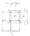
- the construction can be a circle four such as shown in Fig. 2 wherein the solid lines 11 around axial strands 10, 12, 14, 16 show the creation of a portion 22a of cell 24 that is interlocked to a portion 22b of an adjacent cell 26 by dashed lines 13.
- Fig. 3 represents a circle four construction in the form of an I beam.
- a construction called circle three is shown in Fig.
- FIG. 4 wherein solid lines 11 ⁇ around axial yarns 12 ⁇ , 14 ⁇ , 16 ⁇ and 18 ⁇ show creation of a portion 22a ⁇ of cell 24 ⁇ interlocked to a portion 22b ⁇ of cell 26 ⁇ by dashed lines 13 ⁇ .
- Lines 11 ⁇ and 13 ⁇ represent spiralling strands.
- a single cell such as 24 ⁇ may be formed with a central void such as indicated by the numberal 30 and the void may contain an axial strand 32 trapped in the cell by the spiralling of strands 11 ⁇ around axial strands 12 ⁇ , 40, 41, 42, 43, 44, and 45.
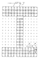
- Fig. 5 represents a circle three construction in the form of an I beam.
- An I beam structure was prepared by using 108 ends of 9000 denier nylon cord as axial yarns, 84 ends of 8200 olefin yarn as the intertwining yarns and 21 ends of 216,000 denier rope as axial yarns to be trapped within a cell as it is formed.
- the twining was carried out by hand movement as detailed above in connection with the circle three construction shown in Fig. 4.
- the outer surfaces of the I beam formation were then given a heavy spatula coating of epoxy resin and encased in a clamped wood form that matched the I beam formation. After 24 hours of curing at room temperature, the wood form was removed. A cross sectional cut was made in I beam formation with a hack saw. Examination of the cut ends showed good epoxy penetration.
Landscapes
- Engineering & Computer Science (AREA)
- Textile Engineering (AREA)
- Manufacturing & Machinery (AREA)
- Chemical & Material Sciences (AREA)
- Composite Materials (AREA)
- Mechanical Engineering (AREA)
- Braiding, Manufacturing Of Bobbin-Net Or Lace, And Manufacturing Of Nets By Knotting (AREA)
- Ropes Or Cables (AREA)
- Woven Fabrics (AREA)
- Moulding By Coating Moulds (AREA)
- Yarns And Mechanical Finishing Of Yarns Or Ropes (AREA)
- Nonwoven Fabrics (AREA)
- Materials For Medical Uses (AREA)
- Reinforced Plastic Materials (AREA)
Abstract
Description
- This invention relates to three-dimensional structures of interlocked strands and more particularly it relates to such structures in composite material.
- Fiber-reinforced plastic structures have been used for many years with increasing success because of their high strength, light weight and ease of fabrication compared to the wood or metal structures which they replace. Fibers such as glass, carbon, ceramic and aramid are popular as reinforcement, and thermosetting as well as thermoplastic resins are common polymeric matrices.
- Braiding with axial yarns is one process for producing such structures and generally comprises forming an array of axial yarns extending substantially parallel to the axis of the structure and interlacing braiding yarns in a pattern through the array so they are interlaced with one another and with the axial yarns. Known braiding patterns does not provide the control of the yarns necessary to locate them at particular locations in the structure so that such locactions can have the characteristics of a particular yarn. This control is not possible with known braiding processes because they have strands that move throughout the process.
- This invention, through a unique interlock twining process, allows a manipulation of strands to form complex shaped structures with precise strand placement so that all component strands at a given location in the structure have a distinct zone of occupancy and as a consequence those zones can have particular characteristics, for example:
- a. expensive yarns with premium properties can be limited to high stress locations,
- b. yarns with high tensile properties can be given one location while yarns with high shear properties can be given a different location.
- c. yarns with good abrasion resistance can be limited to surface locations, and
- d. bulky yarns can be located separately from lean yarns.
- The product is a structure of interlocked strands comprising an array of axial strands extends longitudinally of the structure and a plurality of intertwining strands spiral in a helical path through the structure wherein at least one intertwining strand spirals in a helical path around at least three axial strands located in more than one plane forming a first cell and said one intertwining strand spirals around at least one axial strand of an adjacent second cell comprised of a second set of at least three axial strands formed by at least one other intertwining strand spiralling the second set of axial strands and at least one axial strand of the first cell in a helical path whereby the adjacent cells are interlocked by the intertwining strands. Strands within the product can be given predominant rectilinear orientation or can be given angular orientation. A continuous chain of strands can be provided along a product surface to maximize resistance to lateral bending forces. Small cells can be employed for refinement of shape, where needed, without requiring the fine construction to be employed elsewhere.
- Product weight reduction can be realized by providing cells with hollow centers or voids without sacrifice of structural integrity. The structure around these voids will be completely interlocked. This contrasts with braiding practice where creation of a void can subject the unsupported yarn to futile tension around the void. In summary, the spiraling of one strand around others creates a cell which can be defined as an interlaced combination of strands that has all essentials for interlocking with other cells in the formation of a product. There is no known counterpart for these cells in the prior art. The total product is an assembly of interlocked cells that are arranged to provide the desired form. The cells within a given product can have a variety of characteristics. The yarn components can be different. The cells are like building blocks that can be put together in many different patterns and some cells can have central voids while others may have strands axially oriented through the voids either for strength or for body.
- Fibers such as glass, carbon, ceramic and aramid yarns are commonly used as strands, and thermosetting as well as thermoplastic resins are common polymeric matrices.
- A matrix material may be added to any of the structures made by this invention to form a rigid composite. For example, a three-dimensional braided structure can be shaped as a T-beam and rigidized to form a structural member.
-
- Fig. 1 is a perspective view of a structure according to the invention of two cells interlocked to form a structure.
- Fig. 2 is a motion diagram showing the forming of a structure according to the invention involving four axial strands.
- Fig. 3 is a diagram showing the cell formed according to Fig. 2 in the shape of an I beam.
- Fig. 4 is a motion diagram showing the forming of a structure according to the invention involving three axial strands.
- Fig. 5 is a diagram showing the cell formed according to Fig. 4 in the shape of an I beam.
- Referring now to Fig. 1, the structure of this invention involves two essential categories of strands, i.e., strands designated 10, 12, 14, 16, 18, 20 that have general axial alignments and
strands strands strands structure 22 although other directions will work equally as well. The rate at which the axial strands 10-20 move controls the pitch of the spirals formed bystrands - As stated above, the spirally of one strand around others creates a cell which is then interlocked with other cells to form a total structure. The cells within a given structure can have a variety of characteristics. For example, the strand components can be different yarns. The construction can be a circle four such as shown in Fig. 2 wherein the
solid lines 11 aroundaxial strands portion 22ª ofcell 24 that is interlocked to a portion 22b of anadjacent cell 26 bydashed lines 13. Fig. 3 represents a circle four construction in the form of an I beam. Similarly a construction called circle three is shown in Fig. 4 wherein solid lines 11ʹ around axial yarns 12ʹ, 14ʹ, 16ʹ and 18ʹ show creation of a portion 22aʹ of cell 24ʹ interlocked to a portion 22bʹ of cell 26ʹ by dashed lines 13ʹ. Lines 11ʹ and 13ʹ represent spiralling strands. In addition, a single cell such as 24ʹ may be formed with a central void such as indicated by the numberal 30 and the void may contain anaxial strand 32 trapped in the cell by the spiralling of strands 11ʹ around axial strands 12ʹ, 40, 41, 42, 43, 44, and 45. Fig. 5 represents a circle three construction in the form of an I beam. - An I beam structure was prepared by using 108 ends of 9000 denier nylon cord as axial yarns, 84 ends of 8200 olefin yarn as the intertwining yarns and 21 ends of 216,000 denier rope as axial yarns to be trapped within a cell as it is formed.
- The twining was carried out by hand movement as detailed above in connection with the circle three construction shown in Fig. 4.
- The twining process was continued until a 14 inch length in the form of an I beam was formed using the complete motion pattern of Fig. 5.
- The outer surfaces of the I beam formation were then given a heavy spatula coating of epoxy resin and encased in a clamped wood form that matched the I beam formation. After 24 hours of curing at room temperature, the wood form was removed. A cross sectional cut was made in I beam formation with a hack saw. Examination of the cut ends showed good epoxy penetration.
Claims (8)
Applications Claiming Priority (2)
| Application Number | Priority Date | Filing Date | Title |
|---|---|---|---|
| US07/013,964 US4737399A (en) | 1987-02-12 | 1987-02-12 | Three-dimensional structures of interlocked strands |
| US13964 | 1987-02-12 |
Publications (3)
| Publication Number | Publication Date |
|---|---|
| EP0279585A2 true EP0279585A2 (en) | 1988-08-24 |
| EP0279585A3 EP0279585A3 (en) | 1988-09-07 |
| EP0279585B1 EP0279585B1 (en) | 1991-04-10 |
Family
ID=21762761
Family Applications (1)
| Application Number | Title | Priority Date | Filing Date |
|---|---|---|---|
| EP88301128A Expired - Lifetime EP0279585B1 (en) | 1987-02-12 | 1988-02-11 | Three-dimensional structures of interlocked strands |
Country Status (11)
| Country | Link |
|---|---|
| US (1) | US4737399A (en) |
| EP (1) | EP0279585B1 (en) |
| JP (1) | JPH01207454A (en) |
| KR (1) | KR970008185B1 (en) |
| CN (1) | CN1011518B (en) |
| AU (1) | AU592523B2 (en) |
| BR (1) | BR8800574A (en) |
| CA (1) | CA1295106C (en) |
| DE (1) | DE3862313D1 (en) |
| ES (1) | ES2021427B3 (en) |
| IL (1) | IL85404A (en) |
Cited By (4)
| Publication number | Priority date | Publication date | Assignee | Title |
|---|---|---|---|---|
| WO1991010766A1 (en) * | 1990-01-15 | 1991-07-25 | Albany International Corp. | Braid structure |
| EP0373379A3 (en) * | 1988-12-14 | 1991-11-06 | Airfoil Textron Inc. | Method of making composite articles |
| US5357839A (en) * | 1990-07-12 | 1994-10-25 | Albany International Corp. | Solid braid structure |
| DE4342575A1 (en) * | 1993-10-12 | 1995-04-13 | Textilma Ag | Textile insert for the production of a fiber composite material and fiber composite material |
Families Citing this family (8)
| Publication number | Priority date | Publication date | Assignee | Title |
|---|---|---|---|---|
| CA1309283C (en) * | 1988-02-02 | 1992-10-27 | Ronald Frank Mcconnell | In-line consolidation of braided structures |
| JP2714735B2 (en) * | 1992-05-20 | 1998-02-16 | 財団法人鉄道総合技術研究所 | Large diameter rod made of organic synthetic fiber |
| DE102006031491B4 (en) * | 2005-07-19 | 2010-09-30 | Eurocopter Deutschland Gmbh | Method for producing a three-dimensionally curved fiber composite structural component |
| CN100350088C (en) * | 2006-04-04 | 2007-11-21 | 天津工业大学 | Three-dimensional integral weaving method for multi-directional preform |
| FR3001409B1 (en) * | 2013-01-29 | 2015-07-03 | Herakles | METHOD FOR MANUFACTURING ALVEOLAR STRUCTURE OF CURVED SHAPE IN COMPOSITE MATERIAL |
| CN104099722B (en) * | 2013-04-15 | 2016-03-02 | 台湾百和工业股份有限公司 | Columnar braid and manufacturing method thereof |
| CN103306044A (en) * | 2013-06-13 | 2013-09-18 | 宜兴市华恒高性能纤维织造有限公司 | Three-dimensional overall prefabricated body for reinforcing T-shaped section beam |
| CN103361817B (en) * | 2013-06-26 | 2017-04-05 | 山东鲁普科技有限公司 | Three-dimensional cylindrical rope and manufacture method |
Family Cites Families (6)
| Publication number | Priority date | Publication date | Assignee | Title |
|---|---|---|---|---|
| US1182035A (en) * | 1914-08-08 | 1916-05-09 | Textile Machine Works | Braiding-machine. |
| US3870580A (en) * | 1971-02-25 | 1975-03-11 | Jack T Belcher | Method of manufacturing of a fiber reinforced structure and method of manufacture |
| US3955467A (en) * | 1974-11-25 | 1976-05-11 | Johnson Jr Edwin W | Uni-directional rope |
| FR2497839A1 (en) * | 1981-01-12 | 1982-07-16 | Brochier Fils J | THREE-DIMENSIONAL FABRIC FOR REINFORCING LAMINATE MATERIALS AND SHAPED ELEMENTS OBTAINED FROM SUCH A FABRIC |
| FR2561677B1 (en) * | 1984-03-22 | 1986-11-21 | Vendramini D | MACHINE FOR MANUFACTURING STRUCTURAL ORGANS BY BRAIDING AND STRUCTURAL ORGANS OBTAINED |
| FR2564490B1 (en) * | 1984-05-15 | 1986-09-19 | Aerospatiale | IMPROVEMENTS ON THREE-DIMENSIONAL KNITTED COMPOSITE PROFILES AND PROCESS FOR THEIR MANUFACTURE |
-
1987
- 1987-02-12 US US07/013,964 patent/US4737399A/en not_active Expired - Fee Related
-
1988
- 1988-02-08 AU AU11398/88A patent/AU592523B2/en not_active Expired
- 1988-02-09 JP JP63026731A patent/JPH01207454A/en active Pending
- 1988-02-09 CA CA000558510A patent/CA1295106C/en not_active Expired - Lifetime
- 1988-02-11 IL IL85404A patent/IL85404A/en not_active IP Right Cessation
- 1988-02-11 DE DE8888301128T patent/DE3862313D1/en not_active Expired - Lifetime
- 1988-02-11 BR BR8800574A patent/BR8800574A/en not_active IP Right Cessation
- 1988-02-11 EP EP88301128A patent/EP0279585B1/en not_active Expired - Lifetime
- 1988-02-11 ES ES88301128T patent/ES2021427B3/en not_active Expired - Lifetime
- 1988-02-12 KR KR1019880001347A patent/KR970008185B1/en not_active Expired - Lifetime
- 1988-02-12 CN CN88100683A patent/CN1011518B/en not_active Expired
Cited By (5)
| Publication number | Priority date | Publication date | Assignee | Title |
|---|---|---|---|---|
| EP0373379A3 (en) * | 1988-12-14 | 1991-11-06 | Airfoil Textron Inc. | Method of making composite articles |
| WO1991010766A1 (en) * | 1990-01-15 | 1991-07-25 | Albany International Corp. | Braid structure |
| US5357839A (en) * | 1990-07-12 | 1994-10-25 | Albany International Corp. | Solid braid structure |
| DE4342575A1 (en) * | 1993-10-12 | 1995-04-13 | Textilma Ag | Textile insert for the production of a fiber composite material and fiber composite material |
| US5665451A (en) * | 1993-10-12 | 1997-09-09 | Textilma Ag | Textile insert for producing a fibrous composite material and fibrous composite material comprising such a textile insert |
Also Published As
| Publication number | Publication date |
|---|---|
| KR970008185B1 (en) | 1997-05-21 |
| BR8800574A (en) | 1988-09-27 |
| AU592523B2 (en) | 1990-01-11 |
| ES2021427B3 (en) | 1991-11-01 |
| IL85404A0 (en) | 1988-07-31 |
| CN1011518B (en) | 1991-02-06 |
| CA1295106C (en) | 1992-02-04 |
| CN88100683A (en) | 1988-11-23 |
| EP0279585B1 (en) | 1991-04-10 |
| IL85404A (en) | 1991-06-10 |
| EP0279585A3 (en) | 1988-09-07 |
| KR880010203A (en) | 1988-10-07 |
| JPH01207454A (en) | 1989-08-21 |
| US4737399A (en) | 1988-04-12 |
| DE3862313D1 (en) | 1991-05-16 |
| AU1139888A (en) | 1988-08-18 |
Similar Documents
| Publication | Publication Date | Title |
|---|---|---|
| US4737399A (en) | Three-dimensional structures of interlocked strands | |
| US4719837A (en) | Complex shaped braided structures | |
| EP0308237B1 (en) | Carbon fibre-reinforced composite resin pultrusion products and method for manufacturing the same | |
| AU1568892A (en) | Asymmetric braiding of improved fiber reinforced products | |
| US5021281A (en) | Laminated material reinforced by a multi-dimensional textile structure and method for producing the same | |
| Ko | Braiding | |
| US5665451A (en) | Textile insert for producing a fibrous composite material and fibrous composite material comprising such a textile insert | |
| EP1738005B1 (en) | Method for producing fibre composite semi-finished products by means of a round wickerwork technique | |
| US6086968A (en) | Two- and three-dimensional shaped woven materials | |
| EP0417612B1 (en) | Filament-reinforced resinous structural rod | |
| US4346741A (en) | Three-dimensional woven articles | |
| US6345598B1 (en) | 3-D braided composite valve structure | |
| MX2011004343A (en) | Pi-preform with variable width clevis and related method of forming. | |
| JPH10510012A (en) | Improved braided preforms for composites | |
| WO2009062764A1 (en) | A metal element based textile product with improved widthwise stability | |
| HK138593A (en) | Building element made from a velvet texture and method for its manufacture | |
| KR20010023769A (en) | New and useful improvements in fiber-reinforced composite materials structures and methods of making same | |
| JP3530956B2 (en) | Composite material using composite reinforced yarn, method for producing the same, and structure | |
| US10584491B2 (en) | Truss structure | |
| EP4097291B1 (en) | Cable and method for producing a cable | |
| DE69005242T2 (en) | Fiber-reinforced plastic grate. | |
| EP0034453A1 (en) | Process and apparatus for the manufacture of cellular composites | |
| JP4692870B2 (en) | Plate-like composite material using composite reinforced yarn | |
| JP3731642B2 (en) | Laminated structure of FRP composition | |
| EP0484410B1 (en) | Carbon-brake disk |
Legal Events
| Date | Code | Title | Description |
|---|---|---|---|
| PUAI | Public reference made under article 153(3) epc to a published international application that has entered the european phase |
Free format text: ORIGINAL CODE: 0009012 |
|
| PUAL | Search report despatched |
Free format text: ORIGINAL CODE: 0009013 |
|
| AK | Designated contracting states |
Kind code of ref document: A2 Designated state(s): BE CH DE ES FR GB IT LI NL SE |
|
| AK | Designated contracting states |
Kind code of ref document: A3 Designated state(s): BE CH DE ES FR GB IT LI NL SE |
|
| 17P | Request for examination filed |
Effective date: 19890220 |
|
| 17Q | First examination report despatched |
Effective date: 19891215 |
|
| GRAA | (expected) grant |
Free format text: ORIGINAL CODE: 0009210 |
|
| AK | Designated contracting states |
Kind code of ref document: B1 Designated state(s): BE CH DE ES FR GB IT LI NL SE |
|
| ITF | It: translation for a ep patent filed | ||
| REF | Corresponds to: |
Ref document number: 3862313 Country of ref document: DE Date of ref document: 19910516 |
|
| ET | Fr: translation filed | ||
| PLBE | No opposition filed within time limit |
Free format text: ORIGINAL CODE: 0009261 |
|
| STAA | Information on the status of an ep patent application or granted ep patent |
Free format text: STATUS: NO OPPOSITION FILED WITHIN TIME LIMIT |
|
| 26N | No opposition filed | ||
| EAL | Se: european patent in force in sweden |
Ref document number: 88301128.0 |
|
| REG | Reference to a national code |
Ref country code: GB Ref legal event code: IF02 |
|
| PGFP | Annual fee paid to national office [announced via postgrant information from national office to epo] |
Ref country code: NL Payment date: 20070204 Year of fee payment: 20 |
|
| PGFP | Annual fee paid to national office [announced via postgrant information from national office to epo] |
Ref country code: SE Payment date: 20070206 Year of fee payment: 20 |
|
| PGFP | Annual fee paid to national office [announced via postgrant information from national office to epo] |
Ref country code: GB Payment date: 20070207 Year of fee payment: 20 |
|
| PGFP | Annual fee paid to national office [announced via postgrant information from national office to epo] |
Ref country code: DE Payment date: 20070208 Year of fee payment: 20 |
|
| PGFP | Annual fee paid to national office [announced via postgrant information from national office to epo] |
Ref country code: CH Payment date: 20070214 Year of fee payment: 20 |
|
| PGFP | Annual fee paid to national office [announced via postgrant information from national office to epo] |
Ref country code: ES Payment date: 20070327 Year of fee payment: 20 |
|
| PGFP | Annual fee paid to national office [announced via postgrant information from national office to epo] |
Ref country code: BE Payment date: 20070413 Year of fee payment: 20 Ref country code: IT Payment date: 20070625 Year of fee payment: 20 |
|
| BE20 | Be: patent expired |
Owner name: E.I. *DU PONT DE NEMOURS AND CY Effective date: 20080211 |
|
| REG | Reference to a national code |
Ref country code: GB Ref legal event code: PE20 |
|
| REG | Reference to a national code |
Ref country code: CH Ref legal event code: PL |
|
| NLV7 | Nl: ceased due to reaching the maximum lifetime of a patent |
Effective date: 20080211 |
|
| EUG | Se: european patent has lapsed | ||
| PG25 | Lapsed in a contracting state [announced via postgrant information from national office to epo] |
Ref country code: NL Free format text: LAPSE BECAUSE OF EXPIRATION OF PROTECTION Effective date: 20080211 |
|
| PGFP | Annual fee paid to national office [announced via postgrant information from national office to epo] |
Ref country code: FR Payment date: 20070208 Year of fee payment: 20 |
|
| REG | Reference to a national code |
Ref country code: ES Ref legal event code: FD2A Effective date: 20080212 |
|
| PG25 | Lapsed in a contracting state [announced via postgrant information from national office to epo] |
Ref country code: GB Free format text: LAPSE BECAUSE OF EXPIRATION OF PROTECTION Effective date: 20080210 |
|
| PG25 | Lapsed in a contracting state [announced via postgrant information from national office to epo] |
Ref country code: ES Free format text: LAPSE BECAUSE OF EXPIRATION OF PROTECTION Effective date: 20080212 |