EP0279562B1 - Sleeving system - Google Patents
Sleeving system Download PDFInfo
- Publication number
- EP0279562B1 EP0279562B1 EP88300928A EP88300928A EP0279562B1 EP 0279562 B1 EP0279562 B1 EP 0279562B1 EP 88300928 A EP88300928 A EP 88300928A EP 88300928 A EP88300928 A EP 88300928A EP 0279562 B1 EP0279562 B1 EP 0279562B1
- Authority
- EP
- European Patent Office
- Prior art keywords
- pockets
- slides
- rotatable member
- slide
- Prior art date
- Legal status (The legal status is an assumption and is not a legal conclusion. Google has not performed a legal analysis and makes no representation as to the accuracy of the status listed.)
- Expired - Lifetime
Links
- 239000000463 material Substances 0.000 claims description 55
- 210000002105 tongue Anatomy 0.000 description 17
- 238000000034 method Methods 0.000 description 7
- 238000004806 packaging method and process Methods 0.000 description 5
- 238000003780 insertion Methods 0.000 description 3
- 230000037431 insertion Effects 0.000 description 3
- 230000007246 mechanism Effects 0.000 description 3
- 230000005484 gravity Effects 0.000 description 2
- 238000012856 packing Methods 0.000 description 2
- 238000010276 construction Methods 0.000 description 1
- 238000011109 contamination Methods 0.000 description 1
- 238000004519 manufacturing process Methods 0.000 description 1
- 238000012986 modification Methods 0.000 description 1
- 230000004048 modification Effects 0.000 description 1
- 238000005192 partition Methods 0.000 description 1
- 238000012545 processing Methods 0.000 description 1
- 238000007789 sealing Methods 0.000 description 1
- 238000004513 sizing Methods 0.000 description 1
- 238000003860 storage Methods 0.000 description 1
Images




Classifications
-
- G—PHYSICS
- G03—PHOTOGRAPHY; CINEMATOGRAPHY; ANALOGOUS TECHNIQUES USING WAVES OTHER THAN OPTICAL WAVES; ELECTROGRAPHY; HOLOGRAPHY
- G03D—APPARATUS FOR PROCESSING EXPOSED PHOTOGRAPHIC MATERIALS; ACCESSORIES THEREFOR
- G03D15/00—Apparatus for treating processed material
- G03D15/10—Mounting, e.g. of processed material in a frame
-
- B—PERFORMING OPERATIONS; TRANSPORTING
- B65—CONVEYING; PACKING; STORING; HANDLING THIN OR FILAMENTARY MATERIAL
- B65B—MACHINES, APPARATUS OR DEVICES FOR, OR METHODS OF, PACKAGING ARTICLES OR MATERIALS; UNPACKING
- B65B43/00—Forming, feeding, opening or setting-up containers or receptacles in association with packaging
- B65B43/12—Feeding flexible bags or carton blanks in flat or collapsed state; Feeding flat bags connected to form a series or chain
- B65B43/123—Feeding flat bags connected to form a series or chain
Definitions
- the present invention relates to an apparatus and method for inserting a product such as photographic slides into pockets of a sleeve member automatically in a continuous fashion.
- US-E-28,350 relates to methods and apparatus for advancing and loading a chain of bags, but does not relate to photographic slides.
- DE-A-3030545 discloses an apparatus for packaging photographic slides into envelopes.
- US-A-4055933 discloses a flexible transparent envelope for packaging photographic slides, and a method and apparatus for packaging the slides in the envelopes.
- the present invention operates automatically to insert mounted slides into plastic sleeves so as to reduce the handling costs and to provide an attractive as well as light package for shipping or mailing.
- the plastic sleeves also protect the slide from damage due to fingerprints and other contamination and allow the slides to be visually scanned while in their packages.
- the sizing of the pockets can be made so that the sheets of slides can be fit into standard size envelopes currently used for mail order and over-the-counter sales.
- identification of slides for reorders of prints or extra slides may be accomplished by using write on areas of the sleeve or automatic retrieval of slides can be obtained with machinery that reads characters applied onto the sleeving pockets.
- FIG. 1 a perspective view of the apparatus of the present invention is shown, mounted on a base member 10 and comprising the following major elements:
- the sleeve material 12 may be of the type manufactured and sold by the Unicolor Division of Protosystems Inc. and identified as slide album pages.
- the vacuum sources and the pneumatic actuator in the assembly 52 may be any standard vacuum and air compressor.
- the controller 55 may be a programmable logic controller such as that manufactured and sold by Crouzet Inc. as Model Number CMP 31.
- the rotatable drum 40 is connected to the assembly 52 in such a way that a vacuum is applied to two surfaces of the several-faced drum, and more particularly, to that surface which first receives the sleeve material 12 and that surface which lies adjacent the lifter head 44.
- a vacuum applied to the interior of the drum acting through a plurality of holes in the surface operates to hold the sleeve material onto that surface of the drum.
- the sleeve material is carried along and is brought up to a position just underneath the lifter head 44.
- a second vacuum is applied from assembly 52 to the lifter head 44 so as to pull the upper surface of the sleeve material thereagainst.
- the actuator 46 thereafter lifts slightly thus opening the pocket in the sleeve material for insertion of the slides.
- the shuttle 48 moves under the hopper 30 to receive one or more slides at spaced positions along the shuttle 48. Thereafter, the shuttle 48 is moved back to the position shown, and the three slides are lying in a position adjacent the openings of the pockets in the sleeve material between drum 40 and lifting head 44.
- actuator 25 is actuated moving the pusher tongues 22, 23 and 24 against the slides and pushing them into the open pockets on the sleeve material.
- the controller 55 then causes the actuator 46 to move the lifter 44 away from the sleeve material.
- the drum 40 then rotates to another position where the next row of pockets is now inserted between the drum 40 and the lifter head 44 while the filled row is released by cessation of the vacuum so that the sleeve is removable from the drum 40 for storage packing or mailing.
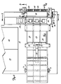
- FIG. 1 a top view of Figure 1 is seen with the roll 12 of sleeve material shown supported by the upright members 14 and 15.
- the tongue member 20 and the three pusher tongues 22, 23 and 24 are shown connected to the actuator 25 by an actuator piston 60.
- Three slides are shown in the shuttle 48 identified by reference numerals 70, 71 and 72 and they are seen to be located in the paths of the pusher tongues 22, 23 and 24, respectively.
- Slides 70, 71 and 72 are shown contained in the shuttle 48 in three receiving areas, better shown in Figure 7 as receiving areas 75, 76 and 77, respectively.
- Shuttle member 48 is actuated by a pneumatic actuator 80 having a pneumatic connection 82 which is connected to the pneumatic actuator assembly 52.
- actuator 25 operating through piston 60 withdraws the pusher tongues 22, 23 and 24 to the left, as shown in Figure 2, at which time the empty shuttle 48 will be actuated by pneumatic actuator 80 to move upwardly in Figure 2 underneath the hopper 30 for receipt of further slides.
- a sensor 78 in hopper 30 senses a slide at the bottom position and notifies the control assembly which then actuates the shuttle 48 and moves it to where the slide at the bottom of the pile at hopper 30 will move into the receiving area 77 occupied by slide 72 in Figure 2.
- the sensor 78 in hopper 30 then senses another slide positioned at the bottom and notifies the control assembly 55. Further motion of shuttle 48 results causing the next slide in the pile to fall into the receiving area 76 occupied by slide 71 in Figure 2.
- the sensor 78 in hopper 30 again senses a slide positioned at the bottom and again notifies the control assembly 55. Thereafter further motion of the shuttle will result allowing the third from the bottom slide in hopper 30 to move into receiving area 75 occupied by slide 70 in Figure 2.
- Actuator 80 will now move the shuttle 48 back to the position shown in Figure 2 for the next operation. If sensor 78 detects the absence of a slide, the control assembly is notified and the process is halted until an operator either overrides the system or adds more slides to hopper 30.
- the sensor 78 may be an electrical or pneumatic switch located at the side of hopper 30 as shown as at the bottom looking up.
- receiving areas 75, 76 and 77 of Figure 7 are separated from one another by abutments 83 and 84, respectively, which abutments are also shown in Figure 2 in or about the sensing area.
- Small switches activated by the slide may be employed in the receiving areas instead of in the hopper if desired.
- Figure 2 also shows the pneumatic actuator 46 operable to move lifter head 44 both upward to open a sleeve pocket and upward and away from the rotating drum 40 as the sleeve material 12 moves into a position to receive slides from shutter 48.
- a vacuum connection 90A is shown in Figure 2 which supplies the vacuum in lifter head 44.
- FIG 3 which is a side view of Figure 1, the elements which have been previously provided with reference numerals will have the same reference numerals.
- the roll of sleeve material 12 is shown mounted for free rotation on the upright member 15 and the sheet of sleeve material is fed from the roll 12 down around a guide roller 90 and then fed along the base 10 under the actuator 25, tongue member 20 and tongue pushers 22, 23 and 24, under the actuator 48 and a second guide roller 92 to one of the sides 94 of the rotatable drum 40 shown as a dashed line hexagon in Figure 3.
- the sheet of sleeve material will be brought up along the surface of side 94 and a vacuum, which will be better described in connection with Figure 11 is applied to the interior of the drum 40 so as to cause the sheet of material to be pressed against side 94. Thereafter, through a motor drive controlled by controller 55 and through a one-way clutch and gear 98, the drum 40 is rotated in a clockwise direction thereby drawing the sheet of sleeve material into a position lying directly under the lifter head 44.
- a sheet of sleeve material is shown in more detail.
- the material is shown to comprise a first or base piece of material such as plastic 100 having a second piece 101 atop thereof and sealed as by heat to the base continuously along areas such as shown as lines 105, 106, 107 and 108.
- the upper sheet material 101 is also sealed to the lower sheet 100 along lines such as shown by dashed lines 110 and 111. While two separate sheets have been shown in Figure 9, the upper sheet 100 and the second sheet 101 may be the same piece of material folded over on itself.
- the upper material 101 is then cut along lines such as shown by reference numerals 115, 116, 117, 118, 119 and 120 so as to provide an access to the interior of the rectangles thus formed by the heat sealing. It is preferred that only the upper surface 101 be cut so as to provide a better container for the slides but some manufacturers may prefer to cut through both the sheets 100 and 101 for ease in manufacture, and such arrangement is acceptable for use with the present invention.
- the sleeve material on roll 12 will consist of a plurality of rows of pockets each consisting of three pockets. While three pockets are shown in connection with Figure 9, it should be understood that any number of pockets could be used, and there is no intention to limit the present disclosure to the use of three pockets per row. There is an advantage which accrues to the use of three pockets, however, in that the size of the slides is normally two inches by two inches and thus three slides side-by-side occupy a length that is approximately six inches. Two of these rows therefore form an area approximately six inches by four inches and after the slides have been injected into the pockets, they may be cut or folded into combinations approximately four inches by six inches so as to accommodate the standard size envelopes used to house photographic positives that are four by six inches in size. This enables ease in packaging and mailing without having to convert to specialized packages.
- the drum 40 contains a plurality of small holes such as identified by reference numerals 120 in the outer surface thereof.
- a vacuum is applied to the interior of drum 40 which operates through the holes 120 to pull the lower surface 100 of the sleeve material against one of the sides of the drum. Thereafter as the drum rotates, the sleeve material is pulled along until it reaches a position where no vacuum is applied and it is thereafter released.
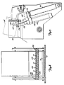
- FIG. 5 A more detailed view of the lifter head 44 can be found in Figure 5.
- the lifter head 44 is shown in two positions, the solid line position being the position in which it holds the plastic material open for insertion of the slides.
- a pneumatic actuator shown in solid lines by reference numeral 46 operates through a linkage consisting of member 128 connected to a second actuator 130 which contains a piston 132 connected to the head 44 at a pivot point 134.
- actuator 130 After touching and capturing the upper material, actuator 130 is actuated and piston 132 raises the upper material slightly to open the pocket. After filling the pocket, actuator 46 is then actuated.
- actuator 46 When actuator 46 is energized by pneumatic pressure from pneumatic controller 52, member 128 will be moved upwardly to the position shown by dashed line 128' and actuator 130 will be moved to a position shown by dashed line 130'. This causes the piston 132 to occupy a position shown by dashed line 132' and it is seen that pivot point 134 is now moved to a point 134' which causes rotation of lifter head 44 around a pivot 138 to a position shown as dashed line 44'. During this motion, the vacuum is overcome and the upper sheet of material released to close the pocket. The lifter head 44 will then be out of contact with the sheet material thereby allowing the drum 40 to rotate another set of pockets into position. Head 44 will then again be lowered to contact position (not shown) and the process is repeated.
- FIG. 6 the shuttle 48 is shown in dashed lines connected by a connection shown as cross-hatched area 142 to a first pneumatic actuator 144 having a piston 146.
- Actuator 144 is also shown connected to a second actuator 150 having a piston 152 bearing against a vertically extending abutment 154 connected to actuator 144.
- Actuator 150 in turn is connected to a third actuator 160 having a piston 162 which bears against a vertical abutment 164 connected to actuator 150 and to actuator 144.
- Actuator 160 is guided by a support member 168 to guide it in motion to the right and left.
- actuator 144 When all of the actuators are deactuated, i.e. all retracted to the left, the shuttle 48 will occupy the position shown in Figure 6a which corresponds to the position shown in Figure 2.
- actuator 144 In order to have the shuttle 48 move under the hopper 30 and receive the slides one at a time, actuator 144 is first actuated by a signal from sensor 78 and the controller 55 operates through the pneumatic actuator 144 to push the piston 146 to the right and thus carry the shuttle 48 to a first position determined by the length of piston 146. This will then lie in a position to receive a first of the slides, i.e. slide 170 of Figure 7, into area 77.
- switch 78 signals the controller 55 that another slide is ready and actuation of actuator 150 results which moves piston 152 to the right thereby carrying actuator 144 and shuttle 48 a further distance to the right determined by the length of piston 152. This will position area 76 of Figure 7 under the hopper 30 and will allow a second slide, i.e. slide 172, to fall into the area 76. Thereafter switch 78 signals controller 55 that another slide is ready and actuation of actuator 160 results which causes piston 162 to move to the right carrying with it actuator 150 and actuator 144 thus moving shuttle 48 a further distance to the right determined by the length of piston 162 sufficient to bring area 75 in Figure 7 underneath the hopper 30 and allow a third slide, i.e. slide 174, to drop into the area 75. Thereafter the pneumatic actuators are caused to reverse and the shuttle 48 moves back into the position such as is shown in Figure 2 with the three slides now in position for insertion into the pockets when called for.
- FIG 4 shows further detail of rotatable drum 40 of Figures 1, 2 and 3.
- the drum 40 is again shown as a hexagon and the sleeve material 12 is shown, as with Figure 3, passing under guide 92 and onto the surface 94.
- Drum 40 has a plurality of partitions extending from the central hub 170 thereof outwardly to the edges of the hexagon by walls 172. This divides the interior of the drum into six compartments of roughly triangular shape. The ends of the drum are sealed but, as better seen in Figure 11, a plurality of holes 178 are formed in one end leading to each of the triangular chambers.
- An end member or manifold 190 is seen in Figure 11, as approximately semi-circular in configuration and contains an aperture 192 large enough only to uncover two of the end holes 178, i.e. the two leading to chambers in the upper left and upper portions of drum 40 in Figure 4.
- the manifold 190 fits over the end of drum 140 around the central shaft and a pneumatic connection to the manifold 190 is shown by reference numeral 195 which applies a vacuum to the interior of the manifold 190 which can only escape through the opening 192. Since this is only applied to two of the apertures 178, it is only those two triangular volumes of the rotatable member 40 that are exposed to the vacuum.
- the lifter head 44 has a substantially square interior to which a vacuum is applied through a port 208 from the connection shown as 90A in Figure 2. This vacuum applies itself through apertures such as 212 in the head member 44 so as to pull the upper sheet member 101 away from the lower sheet member 100 to form a pocket as seen in Figure 4.
- the slides which are shown in Figure 4 as with reference numeral 70, 71 and 72 are pushed to the right by the tongue pushers shown in Figure 4 by reference numerals 22, 23 and 24. The slides therefore enter the area between sheet 101 and 100 and thereafter the tongue members 22, 23 and 24 are withdrawn to the left in Figure 4.
- Head 44 is now rotated upwardly as described in connection with Figure 5 away from the now-filled pocket in sleeve member 12 and drum 40 can now be rotated in a clockwise direction so that the filled pockets will move to a position shown by surface 200 where the vacuum is released from the interior chamber of the drum 40. Now, under the pull of gravity, the sleeve will be lowered to a receiving station not shown.
- Figure 8 shows a more detailed cross sectional view of the tongue actuator 20 wherein it is seen that the pusher tongues 22, 23 and 24 are guided in their movement to the right in Figure 3 by two guide members 220 and 230 fastened together by bolts 233 so as to form rectangular slots for the tongue pushers 22, 23 and 24 to slide in.
- FIG 10 a second side view of the apparatus is shown similar to that in Figure 3, but in Figure 10, a slide mounter apparatus 240 which may be the slide mounter Model SA101 manufactured and sold by Pakon, Inc. is shown connected to the present invention as might be the case in actual practice.
- the mounter operates to mount slides in their cardboard or plastic containers and produce them as an output at a channel 242 which is shown leading to a slide chute 244 and into a feed hopper 246 shaped to receive the output of mounter 240 and seen to be in slightly different form than that of hopper 30 in Figure 3.
- the remainder of the apparatus in Figure 10 is like that shown in Figure 3 and will not be furthered described.
Landscapes
- Engineering & Computer Science (AREA)
- Mechanical Engineering (AREA)
- Physics & Mathematics (AREA)
- General Physics & Mathematics (AREA)
- Making Paper Articles (AREA)
- Supplying Of Containers To The Packaging Station (AREA)
- Sheets, Magazines, And Separation Thereof (AREA)
- Auxiliary Devices For And Details Of Packaging Control (AREA)
- Container Filling Or Packaging Operations (AREA)
Description
- The present invention relates to an apparatus and method for inserting a product such as photographic slides into pockets of a sleeve member automatically in a continuous fashion.
- In the film processing industry after slides have been mounted in cardboard or plastic frames, they are normally packaged into small boxes for shipping and handling. Usually this packing is accomplished by hand and such boxing techniques are not only costly but the box is rather heavy for mailing and the film cannot be viewed without removing the slides from the box which often results in fingerprint smudges.
- US-E-28,350 relates to methods and apparatus for advancing and loading a chain of bags, but does not relate to photographic slides.
- DE-A-3030545 discloses an apparatus for packaging photographic slides into envelopes.
- US-A-4055933 discloses a flexible transparent envelope for packaging photographic slides, and a method and apparatus for packaging the slides in the envelopes.
- The present invention operates automatically to insert mounted slides into plastic sleeves so as to reduce the handling costs and to provide an attractive as well as light package for shipping or mailing. The plastic sleeves also protect the slide from damage due to fingerprints and other contamination and allow the slides to be visually scanned while in their packages. By arranging the pockets in rows, the sizing of the pockets can be made so that the sheets of slides can be fit into standard size envelopes currently used for mail order and over-the-counter sales. Furthermore, identification of slides for reorders of prints or extra slides may be accomplished by using write on areas of the sleeve or automatic retrieval of slides can be obtained with machinery that reads characters applied onto the sleeving pockets.
-
- Figure 1 is a perspective view of a preferred embodiment of the present invention;
- Figure 2 is a top view of a portion of Figure 1;
- Figure 3 is a side view of Figure 1;
- Figure 4 is a cut away side view of Figure 2 taken along the section 4-4;
- Figure 5 is a cut away side view of Figure 2 taken along section 5-5;
- Figure 6 and 6A are a cut away top view of Figure 3 taken along section 6-6;
- Figure 7 is a cut away front view of Figure 2 taken along section 7-7;
- Figure 8 is a cut away front view of Figure 3 taken along section 8-8;
- Figure 9 is a perspective view of the sleeve material and pockets therein;
- Figure 10 is a side view of Figure 1 showing a mounter and an alternate form of hopper useful to combine the present invention automatically with the output of the mounter; and
- Figure 11 is an exploded view of rotating drum and vacuum manifold therefore.
- Referring to Fig. 1, a perspective view of the apparatus of the present invention is shown, mounted on a
base member 10 and comprising the following major elements: - (1) a
roll 12 of sleeve material to be described in connection with Figure 9, mounted for free rotation on a pair ofupright members base 10; - (2) a
tongue member 20 comprising threepusher tongues actuator member 25 extending toward the right. Thetongue member 20 will be better described in connection with Figures 2, 3 and 8; - (3) a
vertical hopper 30 adapted to contain a pile of mountedphotographic slides 32 or other similar products which are to be inserted into the pockets on thesleeve material 12; - (4) a multi-sided rotatable member or
drum 40 which will be better described in connection with Figures 2 and 4, for pulling and positioning the sleeve material fromroll 12 through the apparatus while the slides are being inserted; - (5) a
lifter head 44 operated byactuating mechanism 46 to open the pockets in thesleeve material 12 while such sleeve material is being held by therotatable member 40 so that slides may be inserted. Thelifter head 44 will be better described in connection with Figures 2, 3, 4 and 5; - (6) a
shuttle member 48 to be better described in connection with Figures 6, 6a and 7 operable to move slides from thehopper 30 into a position where thepusher members rotatable member 40 andlifter head 44; - (7) a
pneumatic actuator assembly 52 operable to control the actuation of the vacuums and various actuators causing motion of the elements of the present invention; and - (8) a
control assembly 55 which may include a computer and timer for determining the proper actuating times and positions for the elements of the present invention. - The
sleeve material 12 may be of the type manufactured and sold by the Unicolor Division of Protosystems Inc. and identified as slide album pages. The vacuum sources and the pneumatic actuator in theassembly 52 may be any standard vacuum and air compressor. Thecontroller 55 may be a programmable logic controller such as that manufactured and sold by Crouzet Inc. as Model Number CMP 31. - In operation the
rotatable drum 40 is connected to theassembly 52 in such a way that a vacuum is applied to two surfaces of the several-faced drum, and more particularly, to that surface which first receives thesleeve material 12 and that surface which lies adjacent thelifter head 44. - As the sleeve material from
roll 12 passes over to thedrum 40, a vacuum applied to the interior of the drum acting through a plurality of holes in the surface operates to hold the sleeve material onto that surface of the drum. As thedrum 40 rotates, the sleeve material is carried along and is brought up to a position just underneath thelifter head 44. A second vacuum is applied fromassembly 52 to thelifter head 44 so as to pull the upper surface of the sleeve material thereagainst. Theactuator 46 thereafter lifts slightly thus opening the pocket in the sleeve material for insertion of the slides. - During this time, the
shuttle 48 moves under thehopper 30 to receive one or more slides at spaced positions along theshuttle 48. Thereafter, theshuttle 48 is moved back to the position shown, and the three slides are lying in a position adjacent the openings of the pockets in the sleeve material betweendrum 40 and liftinghead 44. At this time,actuator 25 is actuated moving thepusher tongues controller 55 then causes theactuator 46 to move thelifter 44 away from the sleeve material. Thedrum 40 then rotates to another position where the next row of pockets is now inserted between thedrum 40 and thelifter head 44 while the filled row is released by cessation of the vacuum so that the sleeve is removable from thedrum 40 for storage packing or mailing. - Referring now to Figure 2 wherein elements that are shown in Figure 1 have the same reference numerals, a top view of Figure 1 is seen with the
roll 12 of sleeve material shown supported by theupright members tongue member 20 and the threepusher tongues actuator 25 by anactuator piston 60. Three slides are shown in theshuttle 48 identified byreference numerals pusher tongues actuator member 25 is energized from thepneumatic actuator assembly 52 thepiston 60 will cause thetongue pushers slides lifter head 44 and into the open pockets on the sleeve material coming fromroll 12. -
Slides shuttle 48 in three receiving areas, better shown in Figure 7 as receivingareas Shuttle member 48 is actuated by apneumatic actuator 80 having a pneumatic connection 82 which is connected to thepneumatic actuator assembly 52. After theslides sleeve material 12,actuator 25 operating throughpiston 60 withdraws thepusher tongues empty shuttle 48 will be actuated bypneumatic actuator 80 to move upwardly in Figure 2 underneath thehopper 30 for receipt of further slides. - More particularly in Figure 7, a
sensor 78 inhopper 30 senses a slide at the bottom position and notifies the control assembly which then actuates theshuttle 48 and moves it to where the slide at the bottom of the pile athopper 30 will move into thereceiving area 77 occupied byslide 72 in Figure 2. Thesensor 78 inhopper 30 then senses another slide positioned at the bottom and notifies thecontrol assembly 55. Further motion ofshuttle 48 results causing the next slide in the pile to fall into thereceiving area 76 occupied byslide 71 in Figure 2. Thesensor 78 inhopper 30 again senses a slide positioned at the bottom and again notifies thecontrol assembly 55. Thereafter further motion of the shuttle will result allowing the third from the bottom slide inhopper 30 to move into receivingarea 75 occupied byslide 70 in Figure 2.Actuator 80 will now move theshuttle 48 back to the position shown in Figure 2 for the next operation. Ifsensor 78 detects the absence of a slide, the control assembly is notified and the process is halted until an operator either overrides the system or adds more slides tohopper 30. Thesensor 78 may be an electrical or pneumatic switch located at the side ofhopper 30 as shown as at the bottom looking up. - It should be noted that the receiving
areas abutments - Figure 2 also shows the
pneumatic actuator 46 operable to movelifter head 44 both upward to open a sleeve pocket and upward and away from therotating drum 40 as thesleeve material 12 moves into a position to receive slides fromshutter 48. Avacuum connection 90A is shown in Figure 2 which supplies the vacuum inlifter head 44. - In Figure 3, which is a side view of Figure 1, the elements which have been previously provided with reference numerals will have the same reference numerals. In Figure 3 the roll of
sleeve material 12 is shown mounted for free rotation on theupright member 15 and the sheet of sleeve material is fed from theroll 12 down around aguide roller 90 and then fed along thebase 10 under theactuator 25,tongue member 20 andtongue pushers actuator 48 and asecond guide roller 92 to one of thesides 94 of therotatable drum 40 shown as a dashed line hexagon in Figure 3. The sheet of sleeve material will be brought up along the surface ofside 94 and a vacuum, which will be better described in connection with Figure 11 is applied to the interior of thedrum 40 so as to cause the sheet of material to be pressed againstside 94. Thereafter, through a motor drive controlled bycontroller 55 and through a one-way clutch andgear 98, thedrum 40 is rotated in a clockwise direction thereby drawing the sheet of sleeve material into a position lying directly under thelifter head 44. - Referring for a moment to Figure 9, a sheet of sleeve material is shown in more detail. In Figure 9, the material is shown to comprise a first or base piece of material such as
plastic 100 having asecond piece 101 atop thereof and sealed as by heat to the base continuously along areas such as shown aslines upper sheet material 101 is also sealed to thelower sheet 100 along lines such as shown by dashedlines 110 and 111. While two separate sheets have been shown in Figure 9, theupper sheet 100 and thesecond sheet 101 may be the same piece of material folded over on itself. - As thus described so far, this would form a plurality of closed rectangular areas on the sleeve material. The
upper material 101 is then cut along lines such as shown byreference numerals upper surface 101 be cut so as to provide a better container for the slides but some manufacturers may prefer to cut through both thesheets - As seen, the sleeve material on
roll 12 will consist of a plurality of rows of pockets each consisting of three pockets. While three pockets are shown in connection with Figure 9, it should be understood that any number of pockets could be used, and there is no intention to limit the present disclosure to the use of three pockets per row. There is an advantage which accrues to the use of three pockets, however, in that the size of the slides is normally two inches by two inches and thus three slides side-by-side occupy a length that is approximately six inches. Two of these rows therefore form an area approximately six inches by four inches and after the slides have been injected into the pockets, they may be cut or folded into combinations approximately four inches by six inches so as to accommodate the standard size envelopes used to house photographic positives that are four by six inches in size. This enables ease in packaging and mailing without having to convert to specialized packages. - Referring once again to Figure 2, it is seen that the
drum 40 contains a plurality of small holes such as identified byreference numerals 120 in the outer surface thereof. As will be explained below, a vacuum is applied to the interior ofdrum 40 which operates through theholes 120 to pull thelower surface 100 of the sleeve material against one of the sides of the drum. Thereafter as the drum rotates, the sleeve material is pulled along until it reaches a position where no vacuum is applied and it is thereafter released. During the course of its travel it passes underneath thehead 44 where thehead 44 is lowered and a vacuum applied so as to pull theupper surface 101 of the sleeve material upwardly a slight distance thereby opening the pocket and allowing the slides such as 70, 71 and 72 to be pushed into these pockets by thetongue pushers - As seen in Figure 3, after the slides have been entered into the pockets on the sleeve material, the sleeve material exits the system under the force of gravity and is shown at the right of Figure 3 extending downwardly to be cut or collected as desired.
- A more detailed view of the
lifter head 44 can be found in Figure 5. In Figure 5 thelifter head 44 is shown in two positions, the solid line position being the position in which it holds the plastic material open for insertion of the slides. After the slides have been inserted, a pneumatic actuator shown in solid lines byreference numeral 46 operates through a linkage consisting ofmember 128 connected to asecond actuator 130 which contains apiston 132 connected to thehead 44 at apivot point 134. There may be a third position (not shown) where the lifter head is lower than shown bysolid line position 44 and is in contact with the sleeve material. This position is used to assure that thelifter head 44 will in fact capture the upper material of the pocket. After touching and capturing the upper material,actuator 130 is actuated andpiston 132 raises the upper material slightly to open the pocket. After filling the pocket, actuator 46 is then actuated. When actuator 46 is energized by pneumatic pressure frompneumatic controller 52,member 128 will be moved upwardly to the position shown by dashed line 128' andactuator 130 will be moved to a position shown by dashed line 130'. This causes thepiston 132 to occupy a position shown by dashed line 132' and it is seen thatpivot point 134 is now moved to a point 134' which causes rotation oflifter head 44 around apivot 138 to a position shown as dashed line 44'. During this motion, the vacuum is overcome and the upper sheet of material released to close the pocket. Thelifter head 44 will then be out of contact with the sheet material thereby allowing thedrum 40 to rotate another set of pockets into position.Head 44 will then again be lowered to contact position (not shown) and the process is repeated. - Further details of the shuttle actuator are seen in Figures 6 and 6a. In Figure 6, the
shuttle 48 is shown in dashed lines connected by a connection shown ascross-hatched area 142 to a first pneumatic actuator 144 having a piston 146. Actuator 144 is also shown connected to asecond actuator 150 having apiston 152 bearing against a vertically extendingabutment 154 connected to actuator 144.Actuator 150 in turn is connected to athird actuator 160 having apiston 162 which bears against avertical abutment 164 connected toactuator 150 and to actuator 144.Actuator 160 is guided by asupport member 168 to guide it in motion to the right and left. - When all of the actuators are deactuated, i.e. all retracted to the left, the
shuttle 48 will occupy the position shown in Figure 6a which corresponds to the position shown in Figure 2. In order to have theshuttle 48 move under thehopper 30 and receive the slides one at a time, actuator 144 is first actuated by a signal fromsensor 78 and thecontroller 55 operates through the pneumatic actuator 144 to push the piston 146 to the right and thus carry theshuttle 48 to a first position determined by the length of piston 146. This will then lie in a position to receive a first of the slides, i.e.slide 170 of Figure 7, intoarea 77. - When this has been accomplished, switch 78 signals the
controller 55 that another slide is ready and actuation ofactuator 150 results which movespiston 152 to the right thereby carrying actuator 144 and shuttle 48 a further distance to the right determined by the length ofpiston 152. This will positionarea 76 of Figure 7 under thehopper 30 and will allow a second slide, i.e.slide 172, to fall into thearea 76. Thereafter switch 78signals controller 55 that another slide is ready and actuation ofactuator 160 results which causespiston 162 to move to the right carrying with it actuator 150 and actuator 144 thus moving shuttle 48 a further distance to the right determined by the length ofpiston 162 sufficient to bringarea 75 in Figure 7 underneath thehopper 30 and allow a third slide, i.e. slide 174, to drop into thearea 75. Thereafter the pneumatic actuators are caused to reverse and theshuttle 48 moves back into the position such as is shown in Figure 2 with the three slides now in position for insertion into the pockets when called for. - Figure 4 shows further detail of
rotatable drum 40 of Figures 1, 2 and 3. In Figure 4, thedrum 40 is again shown as a hexagon and thesleeve material 12 is shown, as with Figure 3, passing underguide 92 and onto thesurface 94.Drum 40 has a plurality of partitions extending from thecentral hub 170 thereof outwardly to the edges of the hexagon bywalls 172. This divides the interior of the drum into six compartments of roughly triangular shape. The ends of the drum are sealed but, as better seen in Figure 11, a plurality ofholes 178 are formed in one end leading to each of the triangular chambers. - An end member or
manifold 190 is seen in Figure 11, as approximately semi-circular in configuration and contains an aperture 192 large enough only to uncover two of the end holes 178, i.e. the two leading to chambers in the upper left and upper portions ofdrum 40 in Figure 4. The manifold 190 fits over the end of drum 140 around the central shaft and a pneumatic connection to the manifold 190 is shown by reference numeral 195 which applies a vacuum to the interior of the manifold 190 which can only escape through the opening 192. Since this is only applied to two of theapertures 178, it is only those two triangular volumes of therotatable member 40 that are exposed to the vacuum. Thus, there will be a pressure exerted on thesleeve material 12 againstsurface 94 and against asurface 198 in Figure 4, but no pressure applied tosurfaces sleeve material 12 will be held againstsurfaces - The
lifter head 44 has a substantially square interior to which a vacuum is applied through aport 208 from the connection shown as 90A in Figure 2. This vacuum applies itself through apertures such as 212 in thehead member 44 so as to pull theupper sheet member 101 away from thelower sheet member 100 to form a pocket as seen in Figure 4. After this pocket is opened, the slides which are shown in Figure 4 as withreference numeral reference numerals sheet tongue members -
Head 44 is now rotated upwardly as described in connection with Figure 5 away from the now-filled pocket insleeve member 12 and drum 40 can now be rotated in a clockwise direction so that the filled pockets will move to a position shown by surface 200 where the vacuum is released from the interior chamber of thedrum 40. Now, under the pull of gravity, the sleeve will be lowered to a receiving station not shown. - Figure 8 shows a more detailed cross sectional view of the
tongue actuator 20 wherein it is seen that thepusher tongues guide members bolts 233 so as to form rectangular slots for thetongue pushers - Finally referring to Figure 10, a second side view of the apparatus is shown similar to that in Figure 3, but in Figure 10, a slide mounter apparatus 240 which may be the slide mounter Model SA101 manufactured and sold by Pakon, Inc. is shown connected to the present invention as might be the case in actual practice. The mounter operates to mount slides in their cardboard or plastic containers and produce them as an output at a channel 242 which is shown leading to a slide chute 244 and into a feed hopper 246 shaped to receive the output of mounter 240 and seen to be in slightly different form than that of
hopper 30 in Figure 3. The remainder of the apparatus in Figure 10 is like that shown in Figure 3 and will not be furthered described. - It is therefore seen that I have provided a novel and unique method for packaging slides into plastic sleeves which is both economical and simple in its construction and provides inexpensive, light-weight and easy-to-view containers. Many obvious modifications will occur to those skilled in the art, as for example the drive mechanisms, while shown to be pneumatic could be mechanical and the various forms assumed by the various parts, such as the hexagonal shape for the drum, could be in other shapes, or the mounting mechanisms could all be done in other various ways found in the art. Accordingly, I do not wish to be limited to the specific disclosures used in connection with the preferred embodiments. I intend only to be limited by the following claims.
Claims (9)
- An apparatus for inserting mounted photographic slides into sleeve means (12) which has first and second portions of material fastened together to form a plurality of spaced pockets, the apparatus comprising a rotatable member (40), drive means (55,98) for rotating the rotatable member, first and second force producing means (178,190,195;40) for pulling the first and second portions, respectively, to open a first pocket, and inserting means (20,30,48) operable when the first pocket is open to insert one of the slides into the first pocket, characterized in that:
the rotatable member (40) has a plurality of sides;
the drive means (55,98) are operable to rotate said member (40) from a first position to a second position and to a third position;
the first force producing means (178,190,195) is connected to said rotatable member (40) to produce a force adjacent a first side when the first side is in the first position, the force operable to pull the first portion of material of said sleeve means (12) against the first side so as to pull the plurality of pockets so that a first pocket is brought to the second position as the rotatable member (40) rotates;
the second force producing means (44) is mounted adjacent the second position operable when the first side and the first pocket have reached the second position to pull the second portion of material away from the first portion of material so as to open the first pocket; and
the inserting means (20,30,48) is operable when the first pocket is open to insert a photographic slide into the first pocket, the second force producing means (44) thereafter releasing the second portion of material to close the pocket on the slide and the drive means thereafter rotating the rotatable member (40) to pull the plurality of pockets so that the first pocket is brought to the third position where the first force producing means is released so that the first pocket is removable from the rotatable member (40). - Apparatus according to Claim 1 wherein the first and second force producing means are first and second vacuum producing means, respectively.
- Apparatus according to Claim 2 wherein the second portion of material is translucent plastic to allow viewing of the slides in the pockets.
- Apparatus according to Claim 3 wherein the sleeve means (12) is an elongated sheet, and the first and second portions of material provide the plurality of spaced pockets, the rotatable member (40) operating to pull the sleeve means (12) continuously so that successive pockets are moved by the rotatable member (40) to the first position for attraction by the first vacuum producing means, to the second position for opening and filling the pockets and to the third position for releasing the filled pockets.
- Apparatus according to Claim 4 wherein the inserting means includes:
a hopper (30) for receiving a plurality of slides;
a reciprocal member (48) having a receiving area and movable from a first position to a second position, the receiving area of the reciprocal member (48) in the second position receiving a slide from the hopper (30), the reciprocal member (48) then returning with the slide to the first position; and
a tongue member (20) having a pusher operable when the reciprocal member (48) is in the first position to push the slide from the receiving area into the opened pocket of the sleeve each time the rotatable member (40) is in the second position and the second vacuum producing means (44) has opened the pocket. - Apparatus according to Claim 5 wherein the pockets on the sleeve means (12) are at least three abreast and the reciprocal member (48) has at least three receiving areas to receive at least three slides from the hopper (30) and the tongue member (20) has at least three pushers (22-24) to push the slides into the pockets simultaneously.
- Apparatus according to Claim 2 or 5 further including control means (55) operable to control the rotation of the rotatable member (40), to control the operation of the first and second vacuum producing means (178,190,195,44), to control the inserting means (20,30,48), to produce a timed sequence for rotating the rotatable member (40), opening the pocket, inserting the slide into the pocket, releasing the vacuums and rotating the filled pocket to the third position.
- Apparatus according to Claim 4 or 6 wherein the sleeve means (12) is mounted on a roll and is drawn from the roll by the rotating of the rotatable member (40).
- Apparatus according to Claim 5 further including switch means (78) mounted proximate said hopper (30) for sensing the existence of a slide at the bottom thereof and controlling the reciprocal member (48) accordingly.
Applications Claiming Priority (2)
| Application Number | Priority Date | Filing Date | Title |
|---|---|---|---|
| US07/017,056 US4748799A (en) | 1987-02-20 | 1987-02-20 | Sleeving system |
| US17056 | 1987-02-20 |
Publications (3)
| Publication Number | Publication Date |
|---|---|
| EP0279562A2 EP0279562A2 (en) | 1988-08-24 |
| EP0279562A3 EP0279562A3 (en) | 1989-10-25 |
| EP0279562B1 true EP0279562B1 (en) | 1993-11-10 |
Family
ID=21780469
Family Applications (1)
| Application Number | Title | Priority Date | Filing Date |
|---|---|---|---|
| EP88300928A Expired - Lifetime EP0279562B1 (en) | 1987-02-20 | 1988-02-04 | Sleeving system |
Country Status (7)
| Country | Link |
|---|---|
| US (1) | US4748799A (en) |
| EP (1) | EP0279562B1 (en) |
| JP (1) | JPS63218005A (en) |
| AU (1) | AU588497B2 (en) |
| CA (1) | CA1288991C (en) |
| DE (1) | DE3885475T2 (en) |
| ES (1) | ES2045099T3 (en) |
Families Citing this family (10)
| Publication number | Priority date | Publication date | Assignee | Title |
|---|---|---|---|---|
| DE3708880A1 (en) * | 1987-03-18 | 1988-09-29 | Geimuplast Mundt Kg Peter | POCKET FILM FOR FLAT ITEMS, IN PARTICULAR SLIDES |
| CA1312054C (en) * | 1988-07-14 | 1992-12-29 | Wilbur Gerrans | Photograph slide sleeving system |
| US4977725A (en) * | 1988-07-14 | 1990-12-18 | Pakon, Inc. | Photograph slide sleeving system |
| US5046305A (en) * | 1990-04-06 | 1991-09-10 | Rimage Corporation | Sleever module for disk packaging unit |
| DE4019531C2 (en) * | 1990-06-19 | 2000-10-19 | Johannes Loersch | Method for pocketing sheets brought up one after the other and device for carrying out the method |
| US5367858A (en) * | 1993-01-14 | 1994-11-29 | Development Industries Of Green Bay, Inc. | Sleeving system |
| US5459538A (en) * | 1993-04-07 | 1995-10-17 | Byers Industries, Inc. | Photo mounting equipment |
| US5351466A (en) * | 1993-06-10 | 1994-10-04 | Rimage Corporation | Sleever apparatus with singulate gate |
| DE19527312A1 (en) * | 1995-07-26 | 1997-01-30 | L & N Plast Vertriebs Gmbh | Method, device and film for pocketing slide frames |
| US6820397B2 (en) | 2002-07-26 | 2004-11-23 | Fpna Acquisition Corporation | Continuous banding system for wrapping an elongated article such as a stack of interfolded paper towels |
Family Cites Families (12)
| Publication number | Priority date | Publication date | Assignee | Title |
|---|---|---|---|---|
| US2937483A (en) * | 1958-08-28 | 1960-05-24 | Enbee Transparent Specialty Co | Automatic micro-jacket film inserter |
| US3381447A (en) * | 1966-03-02 | 1968-05-07 | Mccall Corp | Apparatus for filling and closing envelope-type containers |
| US3579948A (en) * | 1968-04-29 | 1971-05-25 | Automated Packaging Corp | Bag handling apparatus and method |
| USRE28350E (en) * | 1968-04-29 | 1975-03-04 | Bag handling apparatus and method | |
| US3807121A (en) * | 1968-10-02 | 1974-04-30 | Geimuplast Mundt Kg Peter | Method of expanding a transparency insertion slit in a slide frame |
| AT306401B (en) * | 1971-03-26 | 1973-04-10 | Florjancic Peter | Slide framing machine |
| US3975888A (en) * | 1972-04-26 | 1976-08-24 | R. A. Jones & Company, Inc. | Method and apparatus for forming, filling and sealing packages |
| US4055933A (en) * | 1975-08-29 | 1977-11-01 | Pako Corporation | Apparatus for packaging photographic slides in envelopes |
| US4237678A (en) * | 1978-03-06 | 1980-12-09 | Forox Corporation | Apparatus for loading film transparencies into pre-closed slide mounts |
| NO148698C (en) * | 1978-05-18 | 1983-11-30 | Alfredo Cavalli | HOUSEHOLDER FOR MANUFACTURING AND MAKING FRESH DOUBLE GOODS. |
| DE3030545A1 (en) * | 1980-08-13 | 1982-03-25 | Photo Studio 13 Hch. Schellenberg AG, Zürich | Automatic insertion equipment for transparencies - has endless belt feed for frames with automatic opening catch |
| US4543771A (en) * | 1982-01-11 | 1985-10-01 | Pako Corporation | Photographic slide mounter |
-
1987
- 1987-02-20 US US07/017,056 patent/US4748799A/en not_active Expired - Lifetime
-
1988
- 1988-02-04 ES ES88300928T patent/ES2045099T3/en not_active Expired - Lifetime
- 1988-02-04 EP EP88300928A patent/EP0279562B1/en not_active Expired - Lifetime
- 1988-02-04 DE DE3885475T patent/DE3885475T2/en not_active Expired - Fee Related
- 1988-02-08 CA CA000558384A patent/CA1288991C/en not_active Expired - Fee Related
- 1988-02-18 AU AU11941/88A patent/AU588497B2/en not_active Ceased
- 1988-02-19 JP JP63037299A patent/JPS63218005A/en active Pending
Also Published As
| Publication number | Publication date |
|---|---|
| AU588497B2 (en) | 1989-09-14 |
| EP0279562A3 (en) | 1989-10-25 |
| EP0279562A2 (en) | 1988-08-24 |
| CA1288991C (en) | 1991-09-17 |
| JPS63218005A (en) | 1988-09-12 |
| DE3885475T2 (en) | 1994-05-19 |
| ES2045099T3 (en) | 1994-01-16 |
| US4748799A (en) | 1988-06-07 |
| AU1194188A (en) | 1988-08-25 |
| DE3885475D1 (en) | 1993-12-16 |
Similar Documents
| Publication | Publication Date | Title |
|---|---|---|
| US4696615A (en) | Copying machine | |
| US5044143A (en) | Method and apparatus for packing flexible packages | |
| US6058684A (en) | Apparatus for packaging paper goods forming a stack | |
| EP0725006B1 (en) | Method and apparatus for packaging compact discs into respective cases | |
| US4748799A (en) | Sleeving system | |
| EP0163201A2 (en) | Process and apparatus for the lifting and carriage of objects placed on tray-like supports | |
| US3420036A (en) | Carton handling system and apparatus | |
| US4942720A (en) | Bottom case loader and method | |
| US4809482A (en) | Packaging system | |
| US3651614A (en) | Packaging of bottles, jars and other articles | |
| JPH0834413A (en) | Cutting and stacking device for foil tube packages | |
| US3683582A (en) | Method for loading containers with articles | |
| EP0549487B1 (en) | Flexible apparatus and process for loading and sealing pouches | |
| US5379574A (en) | Apparatus for packaging individual objects, especially packages, e.g. of prepacked foodstuffs | |
| EP0549484B1 (en) | Flexible apparatus and process for placing packages of different sizes in sleeve type boxes | |
| JP2597074B2 (en) | Surface slide container | |
| US4805379A (en) | Process and apparatus for packaging stacks which consist of nested cuplike objects and have the basic shape of elongate cylinders | |
| US5501065A (en) | Apparatus for packaging individual objects, especially foodstuff packages | |
| US3507090A (en) | Bag loading machine | |
| US3804266A (en) | Strip material packing apparatus | |
| US6189294B1 (en) | Packaging for highly perishable, flexible slices of food, and process for inserting the slices | |
| US3816971A (en) | Device for setting up and filling cardboard boxes with containers | |
| JPH06504632A (en) | Method for automatically packaging photographic prints and apparatus for carrying out this method | |
| US3846960A (en) | Strip material packing apparatus | |
| JPS62182006A (en) | Method and device for packaging polyethylene bags by using endless tube |
Legal Events
| Date | Code | Title | Description |
|---|---|---|---|
| PUAI | Public reference made under article 153(3) epc to a published international application that has entered the european phase |
Free format text: ORIGINAL CODE: 0009012 |
|
| AK | Designated contracting states |
Kind code of ref document: A2 Designated state(s): DE ES FR GB IT |
|
| PUAL | Search report despatched |
Free format text: ORIGINAL CODE: 0009013 |
|
| AK | Designated contracting states |
Kind code of ref document: A3 Designated state(s): DE ES FR GB IT |
|
| 17P | Request for examination filed |
Effective date: 19900205 |
|
| 17Q | First examination report despatched |
Effective date: 19920323 |
|
| GRAA | (expected) grant |
Free format text: ORIGINAL CODE: 0009210 |
|
| AK | Designated contracting states |
Kind code of ref document: B1 Designated state(s): DE ES FR GB IT |
|
| REF | Corresponds to: |
Ref document number: 3885475 Country of ref document: DE Date of ref document: 19931216 |
|
| REG | Reference to a national code |
Ref country code: ES Ref legal event code: FG2A Ref document number: 2045099 Country of ref document: ES Kind code of ref document: T3 |
|
| ITF | It: translation for a ep patent filed | ||
| ET | Fr: translation filed | ||
| PLBE | No opposition filed within time limit |
Free format text: ORIGINAL CODE: 0009261 |
|
| STAA | Information on the status of an ep patent application or granted ep patent |
Free format text: STATUS: NO OPPOSITION FILED WITHIN TIME LIMIT |
|
| 26N | No opposition filed | ||
| PGFP | Annual fee paid to national office [announced via postgrant information from national office to epo] |
Ref country code: FR Payment date: 19960118 Year of fee payment: 9 |
|
| PGFP | Annual fee paid to national office [announced via postgrant information from national office to epo] |
Ref country code: GB Payment date: 19960129 Year of fee payment: 9 |
|
| PGFP | Annual fee paid to national office [announced via postgrant information from national office to epo] |
Ref country code: ES Payment date: 19960215 Year of fee payment: 9 |
|
| PG25 | Lapsed in a contracting state [announced via postgrant information from national office to epo] |
Ref country code: GB Effective date: 19970204 |
|
| PG25 | Lapsed in a contracting state [announced via postgrant information from national office to epo] |
Ref country code: ES Free format text: LAPSE BECAUSE OF NON-PAYMENT OF DUE FEES Effective date: 19970205 |
|
| GBPC | Gb: european patent ceased through non-payment of renewal fee |
Effective date: 19970204 |
|
| PG25 | Lapsed in a contracting state [announced via postgrant information from national office to epo] |
Ref country code: FR Effective date: 19971030 |
|
| REG | Reference to a national code |
Ref country code: FR Ref legal event code: ST |
|
| REG | Reference to a national code |
Ref country code: ES Ref legal event code: FD2A Effective date: 19990405 |
|
| PGFP | Annual fee paid to national office [announced via postgrant information from national office to epo] |
Ref country code: DE Payment date: 20010320 Year of fee payment: 14 |
|
| PG25 | Lapsed in a contracting state [announced via postgrant information from national office to epo] |
Ref country code: DE Free format text: LAPSE BECAUSE OF NON-PAYMENT OF DUE FEES Effective date: 20020903 |
|
| PG25 | Lapsed in a contracting state [announced via postgrant information from national office to epo] |
Ref country code: IT Free format text: LAPSE BECAUSE OF NON-PAYMENT OF DUE FEES;WARNING: LAPSES OF ITALIAN PATENTS WITH EFFECTIVE DATE BEFORE 2007 MAY HAVE OCCURRED AT ANY TIME BEFORE 2007. THE CORRECT EFFECTIVE DATE MAY BE DIFFERENT FROM THE ONE RECORDED. Effective date: 20050204 |