EP0278746A2 - Air admittance valve for use in drainage systems - Google Patents
Air admittance valve for use in drainage systems Download PDFInfo
- Publication number
- EP0278746A2 EP0278746A2 EP88301115A EP88301115A EP0278746A2 EP 0278746 A2 EP0278746 A2 EP 0278746A2 EP 88301115 A EP88301115 A EP 88301115A EP 88301115 A EP88301115 A EP 88301115A EP 0278746 A2 EP0278746 A2 EP 0278746A2
- Authority
- EP
- European Patent Office
- Prior art keywords
- admittance valve
- air
- air admittance
- opening
- closure member
- Prior art date
- Legal status (The legal status is an assumption and is not a legal conclusion. Google has not performed a legal analysis and makes no representation as to the accuracy of the status listed.)
- Withdrawn
Links
- 241000238631 Hexapoda Species 0.000 claims description 3
- 239000013536 elastomeric material Substances 0.000 claims description 2
- 238000010276 construction Methods 0.000 description 2
- 239000002689 soil Substances 0.000 description 2
- 238000009423 ventilation Methods 0.000 description 2
- 230000005484 gravity Effects 0.000 description 1
- 230000037431 insertion Effects 0.000 description 1
- 238000003780 insertion Methods 0.000 description 1
- 239000000463 material Substances 0.000 description 1
- 239000004033 plastic Substances 0.000 description 1
- 229920003023 plastic Polymers 0.000 description 1
- 239000002904 solvent Substances 0.000 description 1
Images

Classifications
-
- E—FIXED CONSTRUCTIONS
- E03—WATER SUPPLY; SEWERAGE
- E03F—SEWERS; CESSPOOLS
- E03F5/00—Sewerage structures
- E03F5/08—Ventilation of sewers
-
- E—FIXED CONSTRUCTIONS
- E03—WATER SUPPLY; SEWERAGE
- E03C—DOMESTIC PLUMBING INSTALLATIONS FOR FRESH WATER OR WASTE WATER; SINKS
- E03C1/00—Domestic plumbing installations for fresh water or waste water; Sinks
- E03C1/12—Plumbing installations for waste water; Basins or fountains connected thereto; Sinks
- E03C1/122—Pipe-line systems for waste water in building
-
- F—MECHANICAL ENGINEERING; LIGHTING; HEATING; WEAPONS; BLASTING
- F16—ENGINEERING ELEMENTS AND UNITS; GENERAL MEASURES FOR PRODUCING AND MAINTAINING EFFECTIVE FUNCTIONING OF MACHINES OR INSTALLATIONS; THERMAL INSULATION IN GENERAL
- F16K—VALVES; TAPS; COCKS; ACTUATING-FLOATS; DEVICES FOR VENTING OR AERATING
- F16K24/00—Devices, e.g. valves, for venting or aerating enclosures
- F16K24/06—Devices, e.g. valves, for venting or aerating enclosures for aerating only
-
- Y—GENERAL TAGGING OF NEW TECHNOLOGICAL DEVELOPMENTS; GENERAL TAGGING OF CROSS-SECTIONAL TECHNOLOGIES SPANNING OVER SEVERAL SECTIONS OF THE IPC; TECHNICAL SUBJECTS COVERED BY FORMER USPC CROSS-REFERENCE ART COLLECTIONS [XRACs] AND DIGESTS
- Y10—TECHNICAL SUBJECTS COVERED BY FORMER USPC
- Y10T—TECHNICAL SUBJECTS COVERED BY FORMER US CLASSIFICATION
- Y10T137/00—Fluid handling
- Y10T137/7722—Line condition change responsive valves
- Y10T137/7837—Direct response valves [i.e., check valve type]
- Y10T137/7897—Vacuum relief type
-
- Y—GENERAL TAGGING OF NEW TECHNOLOGICAL DEVELOPMENTS; GENERAL TAGGING OF CROSS-SECTIONAL TECHNOLOGIES SPANNING OVER SEVERAL SECTIONS OF THE IPC; TECHNICAL SUBJECTS COVERED BY FORMER USPC CROSS-REFERENCE ART COLLECTIONS [XRACs] AND DIGESTS
- Y10—TECHNICAL SUBJECTS COVERED BY FORMER USPC
- Y10T—TECHNICAL SUBJECTS COVERED BY FORMER US CLASSIFICATION
- Y10T137/00—Fluid handling
- Y10T137/7722—Line condition change responsive valves
- Y10T137/7837—Direct response valves [i.e., check valve type]
- Y10T137/7898—Pivoted valves
- Y10T137/7903—Weight biased
Definitions
- This invention relates to an air admission valve for use in drainage systems.
- the opening is arranged at an angle to the vertical, and in a preferred construction the angle is approximately 45°.
- the closure member may seat on the opening by gravity.
- the opening is preferably circular.
- the opening may also have a raised rim surrounding it adapted to be engaged by a seal of elastomeric material on the closure member, which in one construction is conveniently pivoted at its upper end, eg. by means of trunnions on the closure member received in mountings in the housing.
- An air inlet is provided for admitting air into the housing and conveniently this is located at a level below the closure member.
- the air inlet may be annular and may also be provided with an insect net.
- the housing may have a downwardly extending pipe for connection to a pipe of the drainage system, and in this arrangement the pipe may be provided with a rubber bushing.
- valve comprises a circular housing 10 of plastics material closed at the top 11 and having a circular opening 12 in its base through which extends a circular pipe 13.
- the circular pipe is secured to the underside of the top at 15 and has arranged on the right-hand-side a portion 16 inclined at approximately 45° within which is a circular opening 17.
- a closure member 18 Arranged to close the opening 17 is a closure member 18 which is pivoted as seen more clearly in Figure 2 by means of trunnions 20 in an opening 21.
- the underside of the closure member 18 is provided with a rubber seal 22 so that in the closed position it butts against the edge of the opening 17, which is formed with a small upwardly directed rim indicated at 23 to ensure a good seal.
- the rubber seal is secured in place by means of a starlock washer 24.
- a circular opening 26 Parallel with the opening 12 and spaced outwardly therefrom is a circular opening 26 containing an insect cover which although only shown at 27 extends throughout the annular opening 26.
- the base of the pipe 13 which projects below the housing 10 is provided with a shoulder 28 against which abutts a rubber bushing 30 with fins 31.
- the valve body can be fitted into an appropriately sized opening, the rubber bushing and fins being compressed appropriately by insertion into a drainage pipe.
- This is in particular to be designed to be a push fit into a 110mm soil and ventilation pipe.
- the rubber bushing can be removed altogether and the pipe 13 directly solvent welded onto an 83mm PVC soil and ventilation pipe.
- the ground drainage system is designed to be in accordance with BS 5572 : 1978 (code of practice for sanitary pipe work).
Landscapes
- Engineering & Computer Science (AREA)
- General Engineering & Computer Science (AREA)
- Life Sciences & Earth Sciences (AREA)
- Hydrology & Water Resources (AREA)
- Public Health (AREA)
- Water Supply & Treatment (AREA)
- Health & Medical Sciences (AREA)
- Structural Engineering (AREA)
- Environmental & Geological Engineering (AREA)
- Mechanical Engineering (AREA)
- Sink And Installation For Waste Water (AREA)
- Self-Closing Valves And Venting Or Aerating Valves (AREA)
- Lift Valve (AREA)
Abstract
Description
- This invention relates to an air admission valve for use in drainage systems.
- In such drainage systems a valve is required to prevent the release of foul air, and to admit air under conditions of reduced pressure in the discharge pipes and stacks.
- According to the present invention an air admittance valve for use in drainage systems comprises a body with an opening therein through which air passes into the drainage system, and a pivoted closure member adapted to close the opening and openable on a pressure difference between the system and the exterior.
- Preferably the opening is arranged at an angle to the vertical, and in a preferred construction the angle is approximately 45°. In this case the closure member may seat on the opening by gravity.
- The opening is preferably circular. The opening may also have a raised rim surrounding it adapted to be engaged by a seal of elastomeric material on the closure member, which in one construction is conveniently pivoted at its upper end, eg. by means of trunnions on the closure member received in mountings in the housing.
- An air inlet is provided for admitting air into the housing and conveniently this is located at a level below the closure member. The air inlet may be annular and may also be provided with an insect net.
- In one arrangement the housing may have a downwardly extending pipe for connection to a pipe of the drainage system, and in this arrangement the pipe may be provided with a rubber bushing.
- The invention may be performed in various ways and one specific embodiment will now be described by way of example with reference to the accompanying drawings in which:
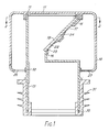
- Figure 1 is a cross section through an air admittance valve according to the present invention and,
- Figure 2 is a section along the line B-B of Figure 1.
- In the drawings the valve comprises a
circular housing 10 of plastics material closed at thetop 11 and having acircular opening 12 in its base through which extends acircular pipe 13. - The circular pipe is secured to the underside of the top at 15 and has arranged on the right-hand-side a
portion 16 inclined at approximately 45° within which is acircular opening 17. Arranged to close the opening 17 is aclosure member 18 which is pivoted as seen more clearly in Figure 2 by means oftrunnions 20 in an opening 21. - The underside of the
closure member 18 is provided with arubber seal 22 so that in the closed position it butts against the edge of theopening 17, which is formed with a small upwardly directed rim indicated at 23 to ensure a good seal. The rubber seal is secured in place by means of astarlock washer 24. - Parallel with the opening 12 and spaced outwardly therefrom is a
circular opening 26 containing an insect cover which although only shown at 27 extends throughout theannular opening 26. - The base of the
pipe 13 which projects below thehousing 10 is provided with a shoulder 28 against which abutts a rubber bushing 30 withfins 31. By means of the rubber bushing the valve body can be fitted into an appropriately sized opening, the rubber bushing and fins being compressed appropriately by insertion into a drainage pipe. This is in particular to be designed to be a push fit into a 110mm soil and ventilation pipe. The rubber bushing can be removed altogether and thepipe 13 directly solvent welded onto an 83mm PVC soil and ventilation pipe. - The ground drainage system is designed to be in accordance with BS 5572 : 1978 (code of practice for sanitary pipe work).
- With the present invention an effective and simple air admittance valve is provided.
Claims (11)
Applications Claiming Priority (2)
| Application Number | Priority Date | Filing Date | Title |
|---|---|---|---|
| GB8703132 | 1987-02-11 | ||
| GB878703132A GB8703132D0 (en) | 1987-02-11 | 1987-02-11 | Air admittance valve |
Publications (2)
| Publication Number | Publication Date |
|---|---|
| EP0278746A2 true EP0278746A2 (en) | 1988-08-17 |
| EP0278746A3 EP0278746A3 (en) | 1988-12-28 |
Family
ID=10612112
Family Applications (1)
| Application Number | Title | Priority Date | Filing Date |
|---|---|---|---|
| EP88301115A Withdrawn EP0278746A3 (en) | 1987-02-11 | 1988-02-10 | Air admittance valve for use in drainage systems |
Country Status (3)
| Country | Link |
|---|---|
| US (1) | US4867802A (en) |
| EP (1) | EP0278746A3 (en) |
| GB (1) | GB8703132D0 (en) |
Cited By (6)
| Publication number | Priority date | Publication date | Assignee | Title |
|---|---|---|---|---|
| EP0409506A1 (en) * | 1989-07-21 | 1991-01-23 | Polypipe Plc | A valve device |
| WO2003021049A1 (en) * | 2001-09-06 | 2003-03-13 | Studor S.A. | Pressure relief device in drainage systems |
| US6532988B1 (en) | 1999-02-03 | 2003-03-18 | Kurt Sture Birger Ericson | Air admittance valve for sanitary waste pipe system |
| EP2239381A1 (en) * | 2009-03-31 | 2010-10-13 | EUR.EX S.r.l. | Backflow flap |
| WO2011030053A1 (en) | 2009-09-09 | 2011-03-17 | Raccords Et Plastiques Nicoll | Pressure equalizing valve |
| EP2115226A4 (en) * | 2007-02-21 | 2014-01-08 | Orc Technology Pty Ltd | Sewer overflow relief device |
Families Citing this family (24)
| Publication number | Priority date | Publication date | Assignee | Title |
|---|---|---|---|---|
| GB8913009D0 (en) * | 1989-06-06 | 1989-07-26 | Frawley Patrick D | One way air admittance valve |
| US5273068A (en) * | 1993-04-20 | 1993-12-28 | Duren Gary S | Air admittance valve for resisting high internal pressure |
| US5682624A (en) * | 1995-06-07 | 1997-11-04 | Ciochetti; Michael James | Vacuum relief safety valve for a swimming pool filter pump system |
| US5971014A (en) * | 1996-09-04 | 1999-10-26 | Duren; Gary S. | Vacuum breaker valve vent fitting clean-out device |
| RU2124667C1 (en) * | 1997-07-21 | 1999-01-10 | Саратовское акционерное производственно-коммерческое открытое общество "НЕФТЕМАШ"-САПКОН | Breathing valve |
| US6161564A (en) * | 1999-04-06 | 2000-12-19 | Cornwall; Kenneth R. | Fire transmission prevention system |
| USD427286S (en) * | 1999-05-25 | 2000-06-27 | Julius Ballanco | Air admittance valve |
| US6415816B1 (en) * | 2000-08-31 | 2002-07-09 | Cherne Industries Incorporated | Air admittance valve assembly |
| US6799600B2 (en) * | 2002-06-04 | 2004-10-05 | Ips Corporation | Protective metal housing for plastic air admittance valve |
| US7395835B1 (en) | 2005-02-16 | 2008-07-08 | Rectorseal Corporation | Air admittance valve |
| US20060201088A1 (en) * | 2005-03-10 | 2006-09-14 | Studor S.A. | Sealed off building drainage and vent system |
| US20060237678A1 (en) * | 2005-04-25 | 2006-10-26 | Lackey Derek J | Metallic Air Admittance Valve |
| US20100139788A1 (en) * | 2005-04-25 | 2010-06-10 | Lackey Derek J | Metallic Air Admittance Valve |
| CN100400947C (en) * | 2005-11-09 | 2008-07-09 | 张官云 | Self-closing valve for tube bursting |
| US7444828B2 (en) * | 2005-11-30 | 2008-11-04 | Hoshizaki Denki Kabushiki Kaisha | Ice discharging structure of ice making mechanism |
| US8459298B1 (en) * | 2006-03-09 | 2013-06-11 | Free Flow Products, LLC | Check valve for drain pipes |
| US7886765B2 (en) * | 2007-09-14 | 2011-02-15 | Chalich Wayne D | Living-hinge air vent valve |
| US20100000614A1 (en) | 2008-07-02 | 2010-01-07 | Zahuranec Terry L | Plumbing supply boxes |
| US8136548B2 (en) * | 2008-08-08 | 2012-03-20 | Watertite Products, Inc. | Air admittance valve |
| US9683355B2 (en) | 2014-04-28 | 2017-06-20 | Ips Corporation | Air admittance valve |
| TWM500184U (en) * | 2015-01-13 | 2015-05-01 | Shower Kaokang Entpr Co Ltd | Air admission valve to prevent helium from overflowing |
| CN109642764B (en) * | 2016-07-15 | 2021-03-30 | 真实制造有限公司 | Ice maker and ice discharging device for vertical jet type ice maker |
| WO2018014035A1 (en) * | 2016-07-15 | 2018-01-18 | Free Flow Products, LLC | Check valve for downspouts |
| US12044000B2 (en) * | 2021-02-09 | 2024-07-23 | Denis Friezner | Method and apparatus for controlling hazardous materials disposed within a storm water control system |
Family Cites Families (21)
| Publication number | Priority date | Publication date | Assignee | Title |
|---|---|---|---|---|
| US623478A (en) * | 1899-04-18 | keene | ||
| DE141588C (en) * | ||||
| US178137A (en) * | 1876-05-30 | Improvement in air or stench traps | ||
| GB190109758A (en) * | 1901-05-10 | 1902-03-13 | Edward Hill S Patent Coupling | Improved Apparatus for Use in Coupling and Uncoupling Railway Trucks or Wagons. |
| GB190110663A (en) * | 1901-05-23 | 1902-05-01 | Carl Daeschner | Process for Separating the Resinous Parts without their Decomposition from Mineral Oils or the like. |
| US735007A (en) * | 1902-05-21 | 1903-07-28 | Robert S Watson | Fresh-air inlet. |
| GB191010663A (en) * | 1910-04-30 | 1910-09-15 | Isaac Shone | Improvements in and connected with Sewerage Systems. |
| GB191209758A (en) * | 1912-04-24 | 1912-07-25 | Henry Jasper Rand | An Improved System of House Drainage. |
| US1978507A (en) * | 1933-03-20 | 1934-10-30 | Henry J Rand | Multiple check valve |
| US2800139A (en) * | 1954-05-04 | 1957-07-23 | Jesse D Langdon | Traps with vacuum breaker |
| US3565107A (en) * | 1969-05-26 | 1971-02-23 | Dillingham Corp | Scupper valve |
| US3815629A (en) * | 1971-07-26 | 1974-06-11 | J Oberholtzer | Sewer relief valve |
| US3941151A (en) * | 1974-10-07 | 1976-03-02 | Biddle Joseph R | Vent pipe check valve |
| DK148966C (en) * | 1977-08-31 | 1986-11-10 | Sture Ericson | AUTOMATIC VALVE MECHANISM FOR CONNECTING THE ATMOSPHERE WITH SPILLS |
| AU511424B2 (en) * | 1978-10-04 | 1980-08-21 | Bjare Element Ab | Pneumatic pressure equaliser |
| NL8200799A (en) * | 1982-02-26 | 1983-09-16 | Dipat Nv | Aeration device. |
| EP0100657B1 (en) * | 1982-07-29 | 1986-10-15 | Kentsub Limited | Air admittance valve |
| BE895071A (en) * | 1982-11-19 | 1983-03-16 | Ericson Sture | AUTOMATIC AIR VALVE DEVICE FOR PIPES |
| AT376288B (en) * | 1983-03-21 | 1984-10-25 | Hutterer & Lechner Kg | PIPE CONNECTION |
| GB2164128B (en) * | 1984-09-08 | 1988-07-27 | Key Terrain Ltd | Air admittance valves |
| DE3474328D1 (en) * | 1984-12-18 | 1988-11-03 | Paul Wenger | Odour trap |
-
1987
- 1987-02-11 GB GB878703132A patent/GB8703132D0/en active Pending
-
1988
- 1988-02-10 EP EP88301115A patent/EP0278746A3/en not_active Withdrawn
- 1988-06-23 US US07/210,479 patent/US4867802A/en not_active Expired - Fee Related
Cited By (11)
| Publication number | Priority date | Publication date | Assignee | Title |
|---|---|---|---|---|
| EP0409506A1 (en) * | 1989-07-21 | 1991-01-23 | Polypipe Plc | A valve device |
| US6532988B1 (en) | 1999-02-03 | 2003-03-18 | Kurt Sture Birger Ericson | Air admittance valve for sanitary waste pipe system |
| WO2003021049A1 (en) * | 2001-09-06 | 2003-03-13 | Studor S.A. | Pressure relief device in drainage systems |
| JP2005501986A (en) * | 2001-09-06 | 2005-01-20 | ステユドール・ソシエテ・アノニム | Pressure relief device for drainage equipment |
| US7025092B2 (en) | 2001-09-06 | 2006-04-11 | Studor S.A. | Positive air pressure attenuation device for drainage systems |
| AU2002328104B2 (en) * | 2001-09-06 | 2007-07-26 | Watertite Products, Inc | Positive air pressure attenuation device for drainage systems |
| KR100879154B1 (en) * | 2001-09-06 | 2009-01-19 | 스튜도르 에스.에이. | Definition of Drainage System Pneumatic Relief |
| EP2115226A4 (en) * | 2007-02-21 | 2014-01-08 | Orc Technology Pty Ltd | Sewer overflow relief device |
| EP2239381A1 (en) * | 2009-03-31 | 2010-10-13 | EUR.EX S.r.l. | Backflow flap |
| WO2011030053A1 (en) | 2009-09-09 | 2011-03-17 | Raccords Et Plastiques Nicoll | Pressure equalizing valve |
| US8984673B2 (en) | 2009-09-09 | 2015-03-24 | Raccords Et Plastiques Nicoll | Pressure equalizing valve |
Also Published As
| Publication number | Publication date |
|---|---|
| US4867802A (en) | 1989-09-19 |
| GB8703132D0 (en) | 1987-03-18 |
| EP0278746A3 (en) | 1988-12-28 |
Similar Documents
| Publication | Publication Date | Title |
|---|---|---|
| EP0278746A2 (en) | Air admittance valve for use in drainage systems | |
| US4650365A (en) | Watertight manhole insert | |
| US6125878A (en) | Sewer inspection chamber with back-flow prevention valve and method and apparatus for installing valve in sewer inspection chamber | |
| US4512492A (en) | Manhole closure with a single liquid impervious, two-way gas pressure relief valve | |
| PL350142A1 (en) | Air admittance valve for sanitary waste pipe system | |
| KR20110128186A (en) | Sealing and sealing means for vent valves in sanitary sewer systems | |
| US7325839B2 (en) | Condensate drain hose fitting for a floor drain | |
| US7566355B2 (en) | Vent protector device for exhaust vents of buildings | |
| AU611942B2 (en) | Valve assembly | |
| US6976398B2 (en) | Liquid sample collection system | |
| US5192156A (en) | Drain apparatus with liquid trap | |
| EP0409506B1 (en) | A valve device | |
| EP0435000A3 (en) | Air outlet with filter | |
| GB2042689A (en) | Devices for Established Communication with the Atmospheric Air | |
| PT1070015E (en) | LIQUID DISPENSER AND CONTROL SYSTEM | |
| CN2168141Y (en) | Gas-water check valve of drainage horizontal tube | |
| GB2051315A (en) | Valve | |
| EP0189605A1 (en) | Liquid sealing device | |
| US4460013A (en) | Pressure-vacuum vent | |
| GB2306179A (en) | Air vent valve | |
| EP0505107A1 (en) | An air admittance valve | |
| GB1586341A (en) | Trapped gulleys | |
| GB2332504A (en) | A chimney flue ventilation cap | |
| EP1308677A2 (en) | Roof ventilation cowl | |
| SE0004126D0 (en) | Valve device for air exchange in buildings and valves included therein |
Legal Events
| Date | Code | Title | Description |
|---|---|---|---|
| PUAI | Public reference made under article 153(3) epc to a published international application that has entered the european phase |
Free format text: ORIGINAL CODE: 0009012 |
|
| AK | Designated contracting states |
Kind code of ref document: A2 Designated state(s): AT BE CH DE ES FR GB GR IT LI LU NL SE |
|
| PUAL | Search report despatched |
Free format text: ORIGINAL CODE: 0009013 |
|
| AK | Designated contracting states |
Kind code of ref document: A3 Designated state(s): AT BE CH DE ES FR GB GR IT LI LU NL SE |
|
| 17P | Request for examination filed |
Effective date: 19890822 |
|
| R17P | Request for examination filed (corrected) |
Effective date: 19890822 |
|
| 17Q | First examination report despatched |
Effective date: 19900323 |
|
| STAA | Information on the status of an ep patent application or granted ep patent |
Free format text: STATUS: THE APPLICATION IS DEEMED TO BE WITHDRAWN |
|
| 18D | Application deemed to be withdrawn |
Effective date: 19900803 |