EP0278395B1 - Holographic display system - Google Patents
Holographic display system Download PDFInfo
- Publication number
- EP0278395B1 EP0278395B1 EP88101602A EP88101602A EP0278395B1 EP 0278395 B1 EP0278395 B1 EP 0278395B1 EP 88101602 A EP88101602 A EP 88101602A EP 88101602 A EP88101602 A EP 88101602A EP 0278395 B1 EP0278395 B1 EP 0278395B1
- Authority
- EP
- European Patent Office
- Prior art keywords
- hologram
- light
- display system
- holograms
- angle
- Prior art date
- Legal status (The legal status is an assumption and is not a legal conclusion. Google has not performed a legal analysis and makes no representation as to the accuracy of the status listed.)
- Expired - Lifetime
Links
Images







Classifications
-
- G—PHYSICS
- G02—OPTICS
- G02B—OPTICAL ELEMENTS, SYSTEMS OR APPARATUS
- G02B27/00—Optical systems or apparatus not provided for by any of the groups G02B1/00 - G02B26/00, G02B30/00
- G02B27/01—Head-up displays
- G02B27/0101—Head-up displays characterised by optical features
- G02B27/0103—Head-up displays characterised by optical features comprising holographic elements
-
- B—PERFORMING OPERATIONS; TRANSPORTING
- B60—VEHICLES IN GENERAL
- B60K—ARRANGEMENT OR MOUNTING OF PROPULSION UNITS OR OF TRANSMISSIONS IN VEHICLES; ARRANGEMENT OR MOUNTING OF PLURAL DIVERSE PRIME-MOVERS IN VEHICLES; AUXILIARY DRIVES FOR VEHICLES; INSTRUMENTATION OR DASHBOARDS FOR VEHICLES; ARRANGEMENTS IN CONNECTION WITH COOLING, AIR INTAKE, GAS EXHAUST OR FUEL SUPPLY OF PROPULSION UNITS IN VEHICLES
- B60K35/00—Instruments specially adapted for vehicles; Arrangement of instruments in or on vehicles
- B60K35/20—Output arrangements, i.e. from vehicle to user, associated with vehicle functions or specially adapted therefor
- B60K35/21—Output arrangements, i.e. from vehicle to user, associated with vehicle functions or specially adapted therefor using visual output, e.g. blinking lights or matrix displays
- B60K35/215—Output arrangements, i.e. from vehicle to user, associated with vehicle functions or specially adapted therefor using visual output, e.g. blinking lights or matrix displays characterised by the combination of multiple visual outputs, e.g. combined instruments with analogue meters and additional displays
-
- G—PHYSICS
- G02—OPTICS
- G02B—OPTICAL ELEMENTS, SYSTEMS OR APPARATUS
- G02B27/00—Optical systems or apparatus not provided for by any of the groups G02B1/00 - G02B26/00, G02B30/00
- G02B27/0018—Optical systems or apparatus not provided for by any of the groups G02B1/00 - G02B26/00, G02B30/00 with means for preventing ghost images
-
- G—PHYSICS
- G02—OPTICS
- G02B—OPTICAL ELEMENTS, SYSTEMS OR APPARATUS
- G02B27/00—Optical systems or apparatus not provided for by any of the groups G02B1/00 - G02B26/00, G02B30/00
- G02B27/01—Head-up displays
- G02B27/0101—Head-up displays characterised by optical features
- G02B27/0103—Head-up displays characterised by optical features comprising holographic elements
- G02B2027/0109—Head-up displays characterised by optical features comprising holographic elements comprising details concerning the making of holograms
-
- G—PHYSICS
- G02—OPTICS
- G02B—OPTICAL ELEMENTS, SYSTEMS OR APPARATUS
- G02B27/00—Optical systems or apparatus not provided for by any of the groups G02B1/00 - G02B26/00, G02B30/00
- G02B27/01—Head-up displays
- G02B27/0101—Head-up displays characterised by optical features
- G02B2027/0112—Head-up displays characterised by optical features comprising device for genereting colour display
- G02B2027/0116—Head-up displays characterised by optical features comprising device for genereting colour display comprising devices for correcting chromatic aberration
-
- G—PHYSICS
- G02—OPTICS
- G02B—OPTICAL ELEMENTS, SYSTEMS OR APPARATUS
- G02B27/00—Optical systems or apparatus not provided for by any of the groups G02B1/00 - G02B26/00, G02B30/00
- G02B27/01—Head-up displays
- G02B27/0101—Head-up displays characterised by optical features
- G02B2027/0118—Head-up displays characterised by optical features comprising devices for improving the contrast of the display / brillance control visibility
- G02B2027/012—Head-up displays characterised by optical features comprising devices for improving the contrast of the display / brillance control visibility comprising devices for attenuating parasitic image effects
-
- G—PHYSICS
- G02—OPTICS
- G02B—OPTICAL ELEMENTS, SYSTEMS OR APPARATUS
- G02B27/00—Optical systems or apparatus not provided for by any of the groups G02B1/00 - G02B26/00, G02B30/00
- G02B27/01—Head-up displays
- G02B27/0101—Head-up displays characterised by optical features
- G02B2027/0145—Head-up displays characterised by optical features creating an intermediate image
-
- G—PHYSICS
- G02—OPTICS
- G02B—OPTICAL ELEMENTS, SYSTEMS OR APPARATUS
- G02B27/00—Optical systems or apparatus not provided for by any of the groups G02B1/00 - G02B26/00, G02B30/00
- G02B27/01—Head-up displays
- G02B27/0149—Head-up displays characterised by mechanical features
- G02B2027/0165—Head-up displays characterised by mechanical features associated with a head-down display
Definitions
- This invention relates to a holographic display system, and specifically relates to, for example, a holographic head-up display system.
- head-up displays Systems commonly used in aircraft to display images of instruments in the field of view of a pilot are termed “head-up displays”.
- the head-up displays employ optical elements or holographic elements to project an image of an instrument into the pilot's field of view as the pilot looks through the forward window of the aircraft.
- United States Patent 4,261,647 and United States Patent 4,655,540 disclose such head-up displays.
- Unites States Patent 4,613,200 discloses a head-up display system usable in an automotive vehicle.
- the head-up display system of United States Patent 4,613,200 utilizes two parallel holographic optical elements to project a virtual image of an indicia display source.
- the virtual image is superimposed in the driver's field of view as the driver looks at the forward scene through the vehicle windshield.
- the parallel arrangement of the holographic optical elements ensures that the virtual image is free of chromatic abberations.
- a display source emits light
- a first hologram receives the light from the display source and diffracts the received light.
- the light from the display source is applied to the first hologram at an incident angle A1 and moves from the first hologram at an outgoing angle B1.
- a second hologram receives the light from the first hologram and diffractively reflects the received light.
- the light diffractively reflected by the second hologram forms an image of the display source in viewer's field of view.
- the light from the first hologram is applied to the second hologram at an incident angle A2 and moves from the second hologram at an outgoing angle B2.
- the first and second holograms are nonparallel to remove a ghost image of the display source which would result from at least one of surface reflections at the first and second holograms.
- the first hologram has an angle ⁇ relative to the second hologram.
- Fig. 1 is a diagram of a holographic display system according to a first embodiment of this invention.
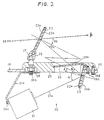
- Fig. 2 is a sectional view of the holographic display system of Fig. 1.
- Fig. 3 is a front view of the holographic display system of Fig. 1.
- Fig. 4 is a graph of the relationships between diffraction efficiency and incident light wavelength in the holograms of Figs. 1-3.
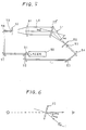
- Fig. 5 is a diagram of an exposure apparatus for manufacturing the holograms of Figs. 1-3.
- Fig. 6 is a diagram of a hologram and a light source.
- Fig. 7 is a diagram of a conventional head-up display system in which a pair of holograms are parallel.
- Fig. 8 and Fig. 9 are diagrams of head-up display systems in which a pair of holograms are nonparallel.
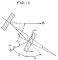
- Fig. 10 is a diagram of a head-up display system.
- Fig. 11 is a diagram of an automotive vehicle equipped with a holographic head-up display system according to a second embodiment of this invention.
- Fig. 12 is a block diagram of an apparatus controlling the cathode ray tube in the head-up display system of Fig. 11.
- Fig. 13 is a diagram of a holographic display system according to a third embodiment of this invention.
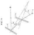
- Fig. 14 is a diagram of a holographic display system according to a fourth embodiment of this invention.
- a holographic head-up display system 20 includes a fluorescent character display tube 21 and a pair of holograms or holographic optical elements 22 and 23 which are all supported on a vehicle dashboard 10.
- the hologram 23 is closer to a vehicle front window or windshield than the other hologram 22 is.
- the display tube 21 emits light indicating information such as a current vehicle speed or a current engine speed.
- the light emitted by the display tube 21 is of a green-based color, having wavelengths around 520 nm.
- the display tube 21 is secured to the vehicle dashboard 10 by means of an attachment plate 24a and bolts 24b and 24c. Specifically, the display tube 21 is fixed to the attachment plate 24a by the bolt 24c. A portion of the vehicle dashboard 10 is securely held between the attachment plate 24a and a base 29 which are connected by the bolt 24b.
- the hologram 22 is centered at an optical axis 21a with respect to the display tube 21 so that the hologram 22 is exposed to the light emitted by the display tube 21.
- the hologram 22 behaves as a reflective diffraction grating causing an incident light beam to be diffracted and reflected. Accordingly, the hologram 22 reflects the light emitted from the display tube 21.
- the hologram 22 is bonded to an attachment plate 22b which is fixed to the base 29 by a bolt 22c. A portion of the base 29 is fixed to the vehicle dashboard 10 by a bolt 22d.
- the diffraction efficiency of the hologram 22 varies with the wavelength of the incident light as shown by the curve A in Fig. 4.
- the hologram 22 serves as a concave mirror reflecting light of wavelengths in a predetermined range.
- the predetermined range of the wavelengths of the reflected light extends between 520 and 530 nm.
- the diffraction efficiency of the hologram 22 peaks at a light wavelength of 525 nm.
- the highest diffraction efficiency of the hologram 22 is around 93%.
- the half-width of the diffraction efficiency peak is 25-30 nm. Accordingly, the hologram 22 selects the light of the predetermined wavelengths and reflects the selected light.
- a surface of the hologram 22 is coated with multilayer films 22a to prevent unwanted reflection and to cut off ultraviolet rays.
- the hologram 23 is exposed to the light reflected by the hologram 22.
- the hologram 23 behaves as a reflective diffraction grating causing an incident light beam to be diffracted and reflected. Accordingly, the hologram 23 reflects the incident light traveled from the hologram 22.
- the hologram 23 serves as a concave mirror projecting a virtual image of the information indicated on the display tube 21. The virtual image is superimposed in the vehicle driver's field of view as the driver looks at the forward scene through the vehicle windshield.
- the hologram 23 is held by a frame 25 which is pivotally supported on the base 29 via a pivot 27.
- the pivot 27 is connected to the base 29 via a combination of a threaded extension and a nut 28.
- the hologram 23 can rotate about the pivot 27 in various directions so that the angle of the hologram 23 can be adjusted relative to the hologram 22.
- the angular adjustment of the hologram 23 is used to vary the location of the virtual image of the indicated information.
- the base 29 has an opening 29a which allows the light to travel from the hologram 22 to the hologram 23.
- a protective glass plate 30 fitted in the opening 29a prevents dust from falling onto the hologram 22.
- Opposite surfaces of the glass plate 30 have antireflection coats.
- the diffraction efficiency of the hologram 23 varies with the wavelength of the incident light as shown by the curve B in Fig. 4.
- the hologram 23 serves as a concave mirror reflecting light of wavelengths in a predetermined range.
- the predetermined range of the wavelengths of the reflected light extends between 520 and 530 nm.
- the diffraction efficiency of the hologram 23 peaks at a light wavelength of 525 nm.
- the highest diffraction efficiency of the hologram 23 is around 73%.
- the hologram 23 selects the light of the predetermined wavelengths and reflects the selected light.
- Both surfaces of the hologram 23 are coated with multilayer films 23a to prevent unwanted reflection and to cut off ultraviolet rays.
- the multilayer films 23a produces a reflectivity of approximately 0.5-1.0%.
- angles of the holograms 22 and 23 are chosen so as to remove unwanted or ghost images of the indicated information. It should be noted that unwanted or ghost images of the indicated information would result from the light diffractively reflected by the hologram 22 and then reflected at the surface of the hologram 23 or from the light reflected at the surface of the hologram 22 and then diffractively reflected by the hologram 23.
- an argon laser 50 emits light having a wavelength of 514 nm.
- the light emitted from the laser 50 is divided into two beams of light by a half mirror 51.
- One beam of light travels from the half mirror 51 to a hologram dry plate 23 ⁇ via mirrors 52, 53, and 54, a convex lens 55, and a pin hole 56.
- This beam of light is applied to a back surface of the hologram dry plate 23 ⁇ as reference light L1 of spherical wave.
- the other beam of light travels from the half mirror 51 to the hologram dry plate 23 ⁇ via mirrors 57 and 58, a convex lens 59, a pin hole 60, and a convex lens 61.
- This beam of light is applied to a front surface of the hologram dry plate 23 ⁇ as object light L2 of plane wave.
- the reference wave L1 and the object wave L2 form a pattern of interference fringes on the hologram dry plate 23 ⁇ .
- the pattern of interference fringes is recorded by photo-sensitive material of the hologram dry plate 23 ⁇ .
- the hologram dry plate 23 ⁇ is subjected to a developing process and a heating process to form the hologram 23.
- the incident angle of the reference wave L1 and the incident angle of the object wave L2 with respect to the hologram dry plate 23 ⁇ are set to predetermined values A02 and B02 respectively.
- the wavelength of the light emitted from the laser 50, the developing process, and the heating process are designed so that the resulting hologram 23 can diffractively reflect only light of wavelengths in the predetermined range as shown in Fig. 4.
- the hologram 23 when the hologram 23 is located relative to a light source 1 so that the light emitted from the source 1 enters the hologram 23 at an incident angle equal to the incident angle A02 of the reference wave L1, the light is diffractively reflected by the hologram 23 at an outgoing angle equal to the incident angle B02 of the object wave L2 and forms a target image of the light source 1.
- the hologram 22 is manufactured in a manner similar to the manufacture of the hologram 23 except for the following point.
- the incident angle of the reference wave and the incident angle of the object wave with respect to a hologram dry plate are set to predetermined values A01 and B01 respectively.
- angles A01, A02, B01, and B01 are chosen so as to satisfy the following equation.
- [cos(B01- ⁇ )/cosB01] ⁇ [(sinA01-sinB01)/(sinA02-sinB02)] -1 (1)
- the character B1 denotes the outgoing angle of the light with respect to the hologram 22
- the character ⁇ denotes the angle of the hologram 22 relative to the hologram 23 (see Figs. 1 and 2).
- Figs. 1 and 2 the character B1 denotes the outgoing angle of the light with respect to the hologram 22
- ⁇ denotes the angle of the hologram 22 relative to the hologram 23 (see Figs. 1 and 2).
- the holograms 22 and 23, and the display tube 21 are relatively positioned so that the light emitted from the display tube 21 will enter the hologram 22 at an incident angle A1 equal to the value A01 and will be diffractively reflected by the hologram 22 at an outgoing angle B1 equal to the value B01, and that the light diffractively reflected by the hologram 22 will enter the hologram 23 at an incident angle A2 equal to the value A02 and will be diffractively reflected by the hologram 23 at an outgoing angle B2 equal to the value B02.
- the angles A1, B1, A2, B2, and ⁇ are set to 40°, 25°, 15°, 30°, and 10° respectively.
- Fig. 7 shows a conventional head-up display system in which a pair of holograms 101 and 102 are arranged in parallel to remove chromatic aberration.
- light emitted from a light source or display tube 103 is diffractively reflected by the holograms 101 and 102 and then the light forms a target image 121 of information indicated on the display tube 103.
- Unwanted ghost images 122, 123, and 124 of the indicated information are formed in addition to the target image 121.
- the ghost image 122 results from the light reflected at the surfaces of the holograms 101 and 102.
- the ghost image 123 results from the light reflected at the surface of the hologram 101 and diffractively reflected by the hologram 102.
- the ghost image 124 results from the light diffractively reflected by the hologram 101 and reflected at the surface of the hologram 102. It should be noted that an incident angle differs from an outgoing angle in diffractive reflection and that an incident angle equals a reflection angle in surface reflection.
- the user In cases where the diffraction efficiencies of the holograms 101 and 102 are 90% and 60% respectively and where each of the holograms 101 and 102 is provided with multi-layer coats producing a reflectivity of 1% in surface reflection, the user generally feels that the unwanted ghost images 123 and 124 are only slightly darker than the target image 121 although the unwanted ghost image 122 is adequately darker than the target image 121. Accordingly, if the ghost images 123 and 124 are close to the target image 121, they cause trouble in looking at the target image 121. When the distance between the holograms 101 and 102 is adequately great, the ghost images 122-124 move out of the normal driver's field of view so that they cause no trouble in looking at the target image 121. It was experimentally found that, in normal automotive vehicles, an adequately great distance between the holograms 101 and 102 could not be maintained because a space accommodating the head-up display system was considerably limited.
- Fig. 8 shows a head-up display system in which a pair of holograms 101 and 102 are nonparallel so that the angle ⁇ of the hologram 101 relative to the hologram 102 differs from zero.
- the angular interval D3 between the ghost image 123 and the target image 121 and the angular interval D4 between the ghost image 124 and the target image 121 also increase. Accordingly, suitable choice of the angle ⁇ of the hologram 101 relative to the hologram 102 allows the brighter ghost images 123 and 124 to be adequately distant from the target image 121.
- Fig. 8 shows a head-up display system in which a pair of holograms 101 and 102 are nonparallel so that the angle ⁇ of the hologram 101 relative to the hologram 102 differs from zero.
- suitable choice of the size of the hologram 102 allows the brighter ghost images 123 and 124 to move out of the normal driver's field of view.
- the reflectivities of the holograms 101 and 102 are in the range of about 0.5-1.0%, the brightness of the remaining unwanted ghost image 122 is smaller than one thousandth of the brightness of the target image 121 so that the ghost image 122 causes essentially no trouble in looking at the target image 121.
- the angle ⁇ of the hologram 101 relative to the hologram 102 is preferably in the range of +5° to +20° and in the range of -5° to -20°.
- the components of display tube light which have wavelengths in the range of ⁇ c- ⁇ c to ⁇ c+ ⁇ c are diffractively reflected by the hologram 22 in the directions corresponding to the angular range of B1- ⁇ B1 to B1+ ⁇ B1. Since the value ⁇ c is extremely small, these components of display tube light are diffractively reflected by the hologram 23 essentially in a common direction corresponding to an angle B2. Accordingly, it is possible to obtain a target image of indicated information without chromatic aberration.
- diffractive reflection by the hologram 101 is generally expressed in the following equation.
- dx(sinA-sinB) ⁇ c/nc (2)
- the characters dx, ⁇ c, nc, A, and B denote the horizontal interval of diffraction grating of the hologram, the wavelength of incident light emitted from the display tube 103, the mean refractive index of the hologram, the incident angle of the light with respect to the hologram, and the outgoing angle of the light with respect to the hologram, respectively.
- the angle Y of the diffraction grating and the angle (Bragg angle) Z between the direction of travel of the light and the diffraction grating are given by the following equations.
- Y (A0-B0)/2 (3)
- Z ( ⁇ -A0-B0)/2 (4)
- A0 denotes the incident angle of reference wave used during the manufacture of the hologram
- B0 denotes the incident angle of object wave used during the manufacture of the hologram.
- the horizontal interval dx of the diffraction grating is also expressed in the following equation.
- ⁇ 0 denotes the wavelength of laser light used in the manufacture of the hologram
- n0 denotes the mean refractive index of the hologram during the exposure process in the manufacture.
- dsinB2/d ⁇ c (dsinA2/d ⁇ c)-(sinA02-sinB02)/ ⁇ 0 (10)
- the hologram display system can be disposed in a limited space within the automotive vehicle around the vehicle dashboard in a manner such as to ensure that the chromatic aberration and the unwanted ghost images are removed.
- the target image of the indicated information is brighter as the diffraction efficiencies of the holograms 22 and 23 increase. It should be noted that the vehicle driver looks at the forward scene through the hologram 23. If the diffraction efficiency of the hologram 23 is excessively high, the components of forward scene light which have wavelengths in the predetermined range are also diffractively reflected by the hologram 23 so that there is a problem in the colors of an image of the forward scene. Accordingly, the diffraction efficiency of the hologram 23 is preferably smaller than 80%. The diffracton efficiency of the hologram 23 is preferably close to 80% for use only during the daytime.
- the diffraction efficiency of the hologram 23 is preferably around 30% from the standpoint of the color problem in the image of the forward scene. Thus, the diffraction efficiency of the hologram 23 is most prefrably in the range of about 30 to 80%. In one example, the diffraction efficiencies of the holograms 22 and 23 are 93% and 73% respectively. In another example, the diffraction efficiencies of the holograms 22 and 23 are 90% and 60% respectively.
- the surfaces of the holograms 22 and 23 are provided with the multilayer coats 22a and 23a which allow the reflectivities of the holograms to be in the range of about 0.5 to 1.0% and thus which remove the ghost image resulting from the light reflected at the surfaces of the holograms.
- the color of light which is used by the head-up display system 20 may be different from the green-based color.
- Lights of a plurality of colors may be indicated by the head-up display system 20.
- the holograms 22 and 23 are modified so that they can act on lights of different colors.
- hologram dry plates are exposed to lights of different colors.
- each of the holograms 22 and 23 is composed of a combination of sub-holograms which can operate on lights of different colors respectively.
- the positions of target images formed by lights of different colors may be differentiated from each other.
- hologram dry plates are exposed to lights of different colors with different focal points.
- the display tube 21 may be replaced by a cathode ray tube, an array of light emitting diodes, or a liquid crystal display exposed to display illumination from its back.
- the display tube 21 may be raplaced by any combination of a fluorescent character display tube, a cathode ray tube, an array of light emitting diodes, and a liquid crystal display.
- the holograms 22 and 23 have essentially flat surfaces.
- the holograms 22 and 23 may have curved surfaces.
- a holographic head-up display system 150 includes a color cathode-ray tube (CRT) 151 attached to a front panel extending within an automotive vehicle.
- the vehicle driver can directly look at the CRT 151 when the driver is seated in position within the vehicle.
- the CRT 151 indicates various information including vehicle operating conditions such as the current vehicle speed or the current engine speed.
- Holograms 152 and 153 are designed and arranged in a manner similar to the holograms 22 and 23 in the embodiment of Figs. 1-3. Accordingly, the holograms 152 and 153 diffractively reflect only light having wavelengths in the predetermined range, that is, light of a green-based color, and transmit light having other wavelengths.
- the hologram 152 extends in front of the CRT 151 and receives the light emitted from the CRT 151.
- the hologram 153 is attached to the vehicle windshield 154 and receives the light reflected by the hologram 152.
- a sensor 140 generates a signal representative of engine speed which is applied to a control circuit 148.
- a sensor 141 generates a signal representative of vehicle speed which is applied to the control circuit 148.
- a switch 142 which can be actuated by the vehicle driver generates a signal representative of an arbitrarily set vehicle speed.
- a sensor 143 generates a signal representative of the quantity of remaining fuel which is applied to the control circuit 148.
- a sensor 144 generates a signal representative of engine coolant temperature which is applied to the control circuit 148.
- a switch 145 which can be actuated by the driver generates a signal for selecting information indicated by the head-up display system 150. The signal generated by the switch 145 is applied to the control circuit 148.
- a switch 146 which can be actuated by the driver generates a signal for changing vehicle headlights between high beam states and low beam states.
- the signal generated by the switch 146 is applied to the control circuit 148.
- a vehicle accessory 147 such as a clock or a navigation system.
- the accessory 147 generates a signal representative of related information which is applied to the control circuit 148.
- the control circuit 148 receives the signals from the devices 140-147 and calculates final values of information data to be displayed. In addition, the control circuit 148 selects information to be indicated by the head-up display system 150. Specifically, when the vehicle speed represented by the signal from the vehicle speed sensor 141 exceeds 100 Km/h or when the engine speed represented by the signal from the engine speed sensor 140 exceeds a given speed, the control circuit 148 outputs a head-up signal of related warning information to a drive circuit 149. As will be described hereinafter, when the drive circuit 149 receives the head-up signal, the drive circuit 149 controls the CRT 151 to allow the related information to be indicated by the head-up display system 150.
- control circuit 148 outputs a head-up signal to the drive circuit 149 when the vehicle speed exceeds a set speed determined by the signal from the vehicle speed setting switch 142, when the quantity of remaining fuel represented by the signal from the fuel sensor 143 drops below a given quantity, when the engine coolant temperature represented by the signal from the engine coolant temperature sensor 144 exceeds a given temperature, or when the vehicle headlights are changed to the high beam states.
- the control circuit 148 outputs a head-up signal of selected information to the drive circuit 149.
- the drive circuit 149 controls the CRT 151 so that the CRT 151 indicates information with light of wavelengths which can be transmitted through the hologram 152. Specifically, in this case, the CRT 151 uses light of a color different from the green-based color. Accordingly, in this case, the vehicle driver can look at the indicated information on the CRT 151 through the hologram 152.
- the drive circuit 149 controls the CRT 151 so that the CRT 151 indicates the related information with light of a wavelength in the predetermined range which is diffractively reflected by the hologram 152. Specifically, in this case, the CRT 151 uses light of the green-based color. Accordingly, in this case, the related information is indicated by the head-up display system 150.
- the control circuit 148 When the vehicle driver actuates the information selection switch 145 and selects the vehicle speed as information to be indicated by the head-up display system 150, the control circuit 148 outputs a head-up signal of the vehicle speed to the drive circuit 149. In response to the head-up signal, the drive circuit 149 controls the CRT 151 so that the wavelength of the light indicative of the vehicle speed emitted by the CRT 151 changes into the predetermined wavelength range or the color of the light indicative of the vehicle speed changes to green, and thus the vehicle speed is indicated by the head-up display system.
- the wavelength of the light indicative of other information emitted by the CRT 151 remains outside the predetermined range, so that the other information is not indicated by the head-up display system 151 but the vehicle driver can look at the other information on the CRT 151 through the hologram 152.
- the light indicative of the vehicle speed is diffractively reflected by the hologram 152 toward the hologram 153 and is then diffractively reflected by the hologram 153, forming an image of the indication of the vehicle speed in the driver's field of front view.
- the diffraction efficiency of the hologram 152 is chosen to be about 50%, part of the light indicative of the vehicle speed passes through the hologram 152 so that the vehicle driver can also directly look at the indication of the vehicle speed on the CRT 151. Generally, 90% of the light indicative of the other information passes through the hologram 152 so that the vehicle driver can directly look at a clear indication of the other information on the CRT 151.
- the control circuit 148 When the vehicle driver actuates the information selection switch 145 and selects information other than the vehicle speed, the control circuit 148 outputs a head-up signal of the selected information to the drive circuit 149.
- the drive circuit 149 controls the CRT 151 and thus the wavelength of the light indicative of the selected information emitted by the CRT 151 changes into the predetermined wavelength range, so that the selected information is indicated by the head-up display system.
- the wavelength of the light indicative of other information emitted by the CRT 151 remains outside the predetermined range, so that the other information is not indicated by the head-up display system 151 but the vehicle driver can directly look at the other information on the CRT 151.
- the light indicative of the selected information is diffractively reflected by the hologram 152 toward the hologram 153 and is then diffractively reflected by the hologram 153, forming an image of the indication of the selected information in the driver's field of front view.
- the control circuit 148 When the engine coolant temperature exceeds the given temperature, when the quantity of remaining fuel drops below the given quantity, or when the vehicle speed exceeds the given speed, the control circuit 148 outputs a head-up signal of the related information to the drive circuit 149.
- the drive circuit 149 controls the CRT 151 and thus the wavelength of the light indicative of the related information emitted by the CRT 151 changes into the predetermined wavelength range, so that the related information is indicated by the head-up display system.
- the wavelength of the light indicative of other inforamtion emitted by the CRT 151 remains outside the predetermined range, so that the other information is not indicated by the head-up display system 151 but the vehicle driver can directly look at the other information on the CRT 151.
- the light indicative of the information related to the head-up signal is diffractively reflected by the hologram 152 toward the hologram 153 and is then diffractively reflected by the hologram 153, forming an image of the indication of the information in the driver's field of front view.
- the color of light which is used by the head-up display system 150 may be different from the green-based color.
- Lights of a plurality of colors may be indicated by the head-up display system 150.
- the holograms 152 and 153 are modified so that they can act on lights of different colors.
- hologram dry plates are exposed to lights of different colors.
- each of the holograms 152 and 153 is composed of a combination of sub-holograms which can operate on lights of different colors respectively. It is preferable that different informations are indicated by lights of different colors respectively.
- the positions of target images formed by lights of different colors may be differentiated from each other. In this case, during the manufacture of the holograms 152 and 153, hologram dry plates are exposed to lights of different colors with different focal points.
- the CRT 151 may be replaced by a fluorescent character tube, an array of light emitting diodes, or a liquid crystal display exposed to display illumination from its back.
- the CRT 151 may be raplaced by any combination of a fluorescent character display tube, a cathode ray tube, an array of light emitting diodes, and a liquid crystal display.
- Fig. 13 shows a third embodiment of this invention, which is similar to the embodiment of Figs. 1-3 except that the angle of the hologram 22 relative to the hologram 23 equals an angle of - ⁇ . It should be noted that, in the embodiment of Figs. 1-3, the angle of the hologram 22 relative to the hologram 23 equals an angle of ⁇ .
- the operation and effect of the embodiment of Fig. 13 are essentially similar to those of the embodiment of Figs. 1-3.
- Fig. 14 shows a fourth embodiment of this invention, which is similar to the embodiment of Figs. 1-3 except that a transmission hologram or Fresnel hologram 222 is used in place of the reflection hologram 22 (see Figs. 1 and 2).
- the light emitted from the display tube 21 and indicating information passes diffractively trough the hologram 222 and is then diffractively reflected by the hologram 23, forming an image of the indicated information in the vehicle driver's field of view.
- the light enters the hologram 222 at an incient angle A1 and moves from the hologram 222 at an outgoing angle B1 as in the embodiment of Figs. 1-3.
Landscapes
- Physics & Mathematics (AREA)
- General Physics & Mathematics (AREA)
- Optics & Photonics (AREA)
- Engineering & Computer Science (AREA)
- Chemical & Material Sciences (AREA)
- Combustion & Propulsion (AREA)
- Transportation (AREA)
- Mechanical Engineering (AREA)
- Instrument Panels (AREA)
Description
- This invention relates to a holographic display system, and specifically relates to, for example, a holographic head-up display system.
- Systems commonly used in aircraft to display images of instruments in the field of view of a pilot are termed "head-up displays". In general, the head-up displays employ optical elements or holographic elements to project an image of an instrument into the pilot's field of view as the pilot looks through the forward window of the aircraft.
- United States Patent 4,261,647 and United States Patent 4,655,540 disclose such head-up displays.
- Unites States Patent 4,613,200 discloses a head-up display system usable in an automotive vehicle. Specifically, the head-up display system of United States Patent 4,613,200 utilizes two parallel holographic optical elements to project a virtual image of an indicia display source. The virtual image is superimposed in the driver's field of view as the driver looks at the forward scene through the vehicle windshield. The parallel arrangement of the holographic optical elements ensures that the virtual image is free of chromatic abberations.
- It was experimentally found that, in a head-up display system which had two parallel holographic optical elements as disclosed in the US patent 4,613,200, there were a desired virtual image and also unwanted virtual images of an indicia display source in the driver's field of view. The unwanted images extended near the desired image or partially overlapped the desired image.
- In view of the above-discussed prior art drawbacks it is therefore the object of the present invention to provide a holographic display system which can remove unwanted images of a display source and which can produce a display source virtual image free of chromatic aberrations.
- This object is solved by a holographic display system according to claim 1.
- In a holographic display system of this invention, a display source emits light, and a first hologram receives the light from the display source and diffracts the received light. The light from the display source is applied to the first hologram at an incident angle A1 and moves from the first hologram at an outgoing angle B1. A second hologram receives the light from the first hologram and diffractively reflects the received light. The light diffractively reflected by the second hologram forms an image of the display source in viewer's field of view. The light from the first hologram is applied to the second hologram at an incident angle A2 and moves from the second hologram at an outgoing angle B2. The first and second holograms are nonparallel to remove a ghost image of the display source which would result from at least one of surface reflections at the first and second holograms. The first hologram has an angle ϑ relative to the second hologram. The angles A1, B1, A2, B2, and ϑ are in a fixed relationship which may be expressed by the following equation:

Accordingly, chromatic aberration which would result from the nonparallel arrangement of the first and second holograms is removed. - Fig. 1 is a diagram of a holographic display system according to a first embodiment of this invention.
- Fig. 2 is a sectional view of the holographic display system of Fig. 1.
- Fig. 3 is a front view of the holographic display system of Fig. 1.
- Fig. 4 is a graph of the relationships between diffraction efficiency and incident light wavelength in the holograms of Figs. 1-3.
- Fig. 5 is a diagram of an exposure apparatus for manufacturing the holograms of Figs. 1-3.
- Fig. 6 is a diagram of a hologram and a light source.
- Fig. 7 is a diagram of a conventional head-up display system in which a pair of holograms are parallel.
- Fig. 8 and Fig. 9 are diagrams of head-up display systems in which a pair of holograms are nonparallel.
- Fig. 10 is a diagram of a head-up display system.
- Fig. 11 is a diagram of an automotive vehicle equipped with a holographic head-up display system according to a second embodiment of this invention.
- Fig. 12 is a block diagram of an apparatus controlling the cathode ray tube in the head-up display system of Fig. 11.
- Fig. 13 is a diagram of a holographic display system according to a third embodiment of this invention.
- Fig. 14 is a diagram of a holographic display system according to a fourth embodiment of this invention.
- With reference to Figs. 1 to 3, a holographic head-up
display system 20 according to a first embodiment of this invention includes a fluorescentcharacter display tube 21 and a pair of holograms or holographicoptical elements vehicle dashboard 10. Thehologram 23 is closer to a vehicle front window or windshield than theother hologram 22 is. - The
display tube 21 emits light indicating information such as a current vehicle speed or a current engine speed. For example, the light emitted by thedisplay tube 21 is of a green-based color, having wavelengths around 520 nm. Thedisplay tube 21 is secured to thevehicle dashboard 10 by means of anattachment plate 24a and bolts 24b and 24c. Specifically, thedisplay tube 21 is fixed to theattachment plate 24a by the bolt 24c. A portion of thevehicle dashboard 10 is securely held between theattachment plate 24a and abase 29 which are connected by the bolt 24b. - The
hologram 22 is centered at anoptical axis 21a with respect to thedisplay tube 21 so that thehologram 22 is exposed to the light emitted by thedisplay tube 21. Thehologram 22 behaves as a reflective diffraction grating causing an incident light beam to be diffracted and reflected. Accordingly, thehologram 22 reflects the light emitted from thedisplay tube 21. - The
hologram 22 is bonded to an attachment plate 22b which is fixed to thebase 29 by a bolt 22c. A portion of thebase 29 is fixed to thevehicle dashboard 10 by abolt 22d. - The diffraction efficiency of the
hologram 22 varies with the wavelength of the incident light as shown by the curve A in Fig. 4. Specifically, thehologram 22 serves as a concave mirror reflecting light of wavelengths in a predetermined range. The predetermined range of the wavelengths of the reflected light extends between 520 and 530 nm. The diffraction efficiency of thehologram 22 peaks at a light wavelength of 525 nm. The highest diffraction efficiency of thehologram 22 is around 93%. The half-width of the diffraction efficiency peak is 25-30 nm. Accordingly, thehologram 22 selects the light of the predetermined wavelengths and reflects the selected light. A surface of thehologram 22 is coated with multilayer films 22a to prevent unwanted reflection and to cut off ultraviolet rays. - The
hologram 23 is exposed to the light reflected by thehologram 22. Thehologram 23 behaves as a reflective diffraction grating causing an incident light beam to be diffracted and reflected. Accordingly, thehologram 23 reflects the incident light traveled from thehologram 22. Specifically, thehologram 23 serves as a concave mirror projecting a virtual image of the information indicated on thedisplay tube 21. The virtual image is superimposed in the vehicle driver's field of view as the driver looks at the forward scene through the vehicle windshield. - The
hologram 23 is held by aframe 25 which is pivotally supported on thebase 29 via apivot 27. Thepivot 27 is connected to thebase 29 via a combination of a threaded extension and anut 28. Thehologram 23 can rotate about thepivot 27 in various directions so that the angle of thehologram 23 can be adjusted relative to thehologram 22. The angular adjustment of thehologram 23 is used to vary the location of the virtual image of the indicated information. - The
base 29 has anopening 29a which allows the light to travel from thehologram 22 to thehologram 23. Aprotective glass plate 30 fitted in theopening 29a prevents dust from falling onto thehologram 22. Opposite surfaces of theglass plate 30 have antireflection coats. - The diffraction efficiency of the
hologram 23 varies with the wavelength of the incident light as shown by the curve B in Fig. 4. Specifically, thehologram 23 serves as a concave mirror reflecting light of wavelengths in a predetermined range. The predetermined range of the wavelengths of the reflected light extends between 520 and 530 nm. The diffraction efficiency of thehologram 23 peaks at a light wavelength of 525 nm. The highest diffraction efficiency of thehologram 23 is around 73%. Accordingly, thehologram 23 selects the light of the predetermined wavelengths and reflects the selected light. Both surfaces of thehologram 23 are coated withmultilayer films 23a to prevent unwanted reflection and to cut off ultraviolet rays. Themultilayer films 23a produces a reflectivity of approximately 0.5-1.0%. - The angles of the
holograms hologram 22 and then reflected at the surface of thehologram 23 or from the light reflected at the surface of thehologram 22 and then diffractively reflected by thehologram 23. - The manufacture of the
hologram 23 will be described hereinafter. As shown in Fig. 5, anargon laser 50 emits light having a wavelength of 514 nm. The light emitted from thelaser 50 is divided into two beams of light by ahalf mirror 51. One beam of light travels from thehalf mirror 51 to a hologram dry plate 23ʹ viamirrors convex lens 55, and apin hole 56. This beam of light is applied to a back surface of the hologram dry plate 23ʹ as reference light L1 of spherical wave. The other beam of light travels from thehalf mirror 51 to the hologram dry plate 23ʹ viamirrors convex lens 59, apin hole 60, and aconvex lens 61. This beam of light is applied to a front surface of the hologram dry plate 23ʹ as object light L2 of plane wave. The reference wave L1 and the object wave L2 form a pattern of interference fringes on the hologram dry plate 23ʹ. The pattern of interference fringes is recorded by photo-sensitive material of the hologram dry plate 23ʹ. The hologram dry plate 23ʹ is subjected to a developing process and a heating process to form thehologram 23. The incident angle of the reference wave L1 and the incident angle of the object wave L2 with respect to the hologram dry plate 23ʹ are set to predetermined values A02 and B02 respectively. The wavelength of the light emitted from thelaser 50, the developing process, and the heating process are designed so that the resultinghologram 23 can diffractively reflect only light of wavelengths in the predetermined range as shown in Fig. 4. - As shown in Fig. 6, when the
hologram 23 is located relative to a light source 1 so that the light emitted from the source 1 enters thehologram 23 at an incident angle equal to the incident angle A02 of the reference wave L1, the light is diffractively reflected by thehologram 23 at an outgoing angle equal to the incident angle B02 of the object wave L2 and forms a target image of the light source 1. - The
hologram 22 is manufactured in a manner similar to the manufacture of thehologram 23 except for the following point. The incident angle of the reference wave and the incident angle of the object wave with respect to a hologram dry plate are set to predetermined values A01 and B01 respectively. - In order to compensate aberration, the angles A01, A02, B01, and B01 are chosen so as to satisfy the following equation.

where the character B1 denotes the outgoing angle of the light with respect to thehologram 22, and the character ϑ denotes the angle of thehologram 22 relative to the hologram 23 (see Figs. 1 and 2). As shown in Figs. 1 and 2, theholograms display tube 21 are relatively positioned so that the light emitted from thedisplay tube 21 will enter thehologram 22 at an incident angle A1 equal to the value A01 and will be diffractively reflected by thehologram 22 at an outgoing angle B1 equal to the value B01, and that the light diffractively reflected by thehologram 22 will enter thehologram 23 at an incident angle A2 equal to the value A02 and will be diffractively reflected by thehologram 23 at an outgoing angle B2 equal to the value B02. For example, the angles A1, B1, A2, B2, and ϑ are set to 40°, 25°, 15°, 30°, and 10° respectively. - The
display tube 21 emits information-indicating light toward thehologram 22. Thehologram 22 selects the light of wavelengths in the predetermined range (λc-Δλc to λc+Δλc) and diffractively reflects the selected light toward thehologram 23 at outgoing angles (B1-ΔB1 to B1+ΔB1). Since the equation (1) is satisfied, all the light moved from thehologram 22 to thehologram 23 is diffractively reflected by thehologram 23 in the direction corresponding to the outgoing angle B2. Accordingly, it is possible to obtain a clear image of the indicated information without chromatic aberration. The setting of the angle ϑ of thehologram 22 relative to thehologram 23 ensures that the unwanted ghost images are acceptably separate from the target image of the indicated information or that the unwanted ghost images are removed. - Fig. 7 shows a conventional head-up display system in which a pair of
holograms display tube 103 is diffractively reflected by theholograms display tube 103.Unwanted ghost images ghost image 122 results from the light reflected at the surfaces of theholograms ghost image 123 results from the light reflected at the surface of thehologram 101 and diffractively reflected by thehologram 102. Theghost image 124 results from the light diffractively reflected by thehologram 101 and reflected at the surface of thehologram 102. It should be noted that an incident angle differs from an outgoing angle in diffractive reflection and that an incident angle equals a reflection angle in surface reflection. - In cases where the diffraction efficiencies of the
holograms holograms unwanted ghost images unwanted ghost image 122 is adequately darker than the target image 121. Accordingly, if theghost images holograms holograms - Fig. 8 shows a head-up display system in which a pair of
holograms hologram 101 relative to thehologram 102 differs from zero. In the display system of Fig. 8, as the angle ϑ of thehologram 101 relative to thehologram 102 increases, the angular interval D3 between theghost image 123 and the target image 121 and the angular interval D4 between theghost image 124 and the target image 121 also increase. Accordingly, suitable choice of the angle ϑ of thehologram 101 relative to thehologram 102 allows thebrighter ghost images hologram 102 allows thebrighter ghost images holograms unwanted ghost image 122 is smaller than one thousandth of the brightness of the target image 121 so that theghost image 122 causes essentially no trouble in looking at the target image 121. - As the angle ϑ of the
hologram 101 relative to thehologram 102 increases, the ghost images are more effectively removed. When the angle ϑ of thehologram 101 relative to thehologram 102 is excessively large, the target image is distorted unacceptably and a problem occurs in the field where the target image extends. Accordingly, the angle ϑ of thehologram 101 relative to thehologram 102, that is, the angle ϑ of thehologram 22 relative to thehologram 23 in the display system of Figs. 1-3, is preferably in the range of +5° to +20° and in the range of -5° to -20°. - In the case where the angles A1, B1, A2, and B2 are equal to the angles A01, B01, A02, and B02 respectively, the components of display tube light which have wavelengths in the range of λc-Δλc to λc+Δλc are diffractively reflected by the
hologram 22 in the directions corresponding to the angular range of B1-ΔB1 to B1+ΔB1. Since the value Δλc is extremely small, these components of display tube light are diffractively reflected by thehologram 23 essentially in a common direction corresponding to an angle B2. Accordingly, it is possible to obtain a target image of indicated information without chromatic aberration. - In a head-up display system including a
hologram 101 and adisplay tube 103 as shown in Fig. 10, diffractive reflection by thehologram 101 is generally expressed in the following equation.

where the characters dx, λc, nc, A, and B denote the horizontal interval of diffraction grating of the hologram, the wavelength of incident light emitted from thedisplay tube 103, the mean refractive index of the hologram, the incident angle of the light with respect to the hologram, and the outgoing angle of the light with respect to the hologram, respectively. - The angle Y of the diffraction grating and the angle (Bragg angle) Z between the direction of travel of the light and the diffraction grating are given by the following equations.

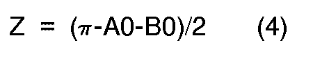
where the character A0 denotes the incident angle of reference wave used during the manufacture of the hologram, and the character B0 denotes the incident angle of object wave used during the manufacture of the hologram. - The horizontal interval dx of the diffraction grating is also expressed in the following equation.

where the character λ0 denotes the wavelength of laser light used in the manufacture of the hologram, and the character n0 denotes the mean refractive index of the hologram during the exposure process in the manufacture. - The equations (2) and (5) are combined to form the following equation giving the outgoing angle B.

This equation (6) can be applied to thehologram 23 as well as thehologram 22. - Under conditions where the mean refractive index nc equals the mean refractive index n0, the equation (6) is rewritten with respect to the
hologram 22 as follows.

Also, the equation (6) is rewritten with respect to thehologram 23 as follows.

In view of the fact that theholograms - The equations (7) and (8) are differentiated with λc and the following equations are derived.


It should be noted that dsinA1/dλc equals 0. Since A2=B1-ϑ, the following equation is derived from the equations (9) and (10).

where

When the incident angles A1 and A2 are equal to the incident angles A01 and A02 of the reference rays used during the exposure processes, the outgoing angles B1 and B2 are equal to the incident angles B01 and B02 of the object rays used during the exposure processes respectively. Accordingly, the equation (12) is converted into the following equation.

When theholograms holograms holograms display tube 21 is thus allowed, the hologram display system can be disposed in a limited space within the automotive vehicle around the vehicle dashboard in a manner such as to ensure that the chromatic aberration and the unwanted ghost images are removed. - The target image of the indicated information is brighter as the diffraction efficiencies of the
holograms hologram 23. If the diffraction efficiency of thehologram 23 is excessively high, the components of forward scene light which have wavelengths in the predetermined range are also diffractively reflected by thehologram 23 so that there is a problem in the colors of an image of the forward scene. Accordingly, the diffraction efficiency of thehologram 23 is preferably smaller than 80%. The diffracton efficiency of thehologram 23 is preferably close to 80% for use only during the daytime. The diffraction efficiency of thehologram 23 is preferably around 30% from the standpoint of the color problem in the image of the forward scene. Thus, the diffraction efficiency of thehologram 23 is most prefrably in the range of about 30 to 80%. In one example, the diffraction efficiencies of theholograms holograms - As described previously, the surfaces of the
holograms multilayer coats 22a and 23a which allow the reflectivities of the holograms to be in the range of about 0.5 to 1.0% and thus which remove the ghost image resulting from the light reflected at the surfaces of the holograms. - It should be noted that the color of light which is used by the head-up
display system 20 may be different from the green-based color. - Lights of a plurality of colors may be indicated by the head-up
display system 20. In this case, theholograms holograms holograms holograms - The
display tube 21 may be replaced by a cathode ray tube, an array of light emitting diodes, or a liquid crystal display exposed to display illumination from its back. In addition, thedisplay tube 21 may be raplaced by any combination of a fluorescent character display tube, a cathode ray tube, an array of light emitting diodes, and a liquid crystal display. - In general, the
holograms holograms - With reference to Fig. 11, a holographic head-up
display system 150 according to a second embodiment of this invention includes a color cathode-ray tube (CRT) 151 attached to a front panel extending within an automotive vehicle. The vehicle driver can directly look at theCRT 151 when the driver is seated in position within the vehicle. TheCRT 151 indicates various information including vehicle operating conditions such as the current vehicle speed or the current engine speed.Holograms holograms holograms hologram 152 extends in front of theCRT 151 and receives the light emitted from theCRT 151. Thehologram 153 is attached to thevehicle windshield 154 and receives the light reflected by thehologram 152. - As shown in Fig. 12, a
sensor 140 generates a signal representative of engine speed which is applied to acontrol circuit 148. Asensor 141 generates a signal representative of vehicle speed which is applied to thecontrol circuit 148. Aswitch 142 which can be actuated by the vehicle driver generates a signal representative of an arbitrarily set vehicle speed. Asensor 143 generates a signal representative of the quantity of remaining fuel which is applied to thecontrol circuit 148. Asensor 144 generates a signal representative of engine coolant temperature which is applied to thecontrol circuit 148. A switch 145 which can be actuated by the driver generates a signal for selecting information indicated by the head-updisplay system 150. The signal generated by the switch 145 is applied to thecontrol circuit 148. Aswitch 146 which can be actuated by the driver generates a signal for changing vehicle headlights between high beam states and low beam states. The signal generated by theswitch 146 is applied to thecontrol circuit 148. In addition, there is avehicle accessory 147 such as a clock or a navigation system. Theaccessory 147 generates a signal representative of related information which is applied to thecontrol circuit 148. - The
control circuit 148 receives the signals from the devices 140-147 and calculates final values of information data to be displayed. In addition, thecontrol circuit 148 selects information to be indicated by the head-updisplay system 150. Specifically, when the vehicle speed represented by the signal from thevehicle speed sensor 141 exceeds 100 Km/h or when the engine speed represented by the signal from theengine speed sensor 140 exceeds a given speed, thecontrol circuit 148 outputs a head-up signal of related warning information to adrive circuit 149. As will be described hereinafter, when thedrive circuit 149 receives the head-up signal, thedrive circuit 149 controls theCRT 151 to allow the related information to be indicated by the head-updisplay system 150. Furthermore, thecontrol circuit 148 outputs a head-up signal to thedrive circuit 149 when the vehicle speed exceeds a set speed determined by the signal from the vehiclespeed setting switch 142, when the quantity of remaining fuel represented by the signal from thefuel sensor 143 drops below a given quantity, when the engine coolant temperature represented by the signal from the enginecoolant temperature sensor 144 exceeds a given temperature, or when the vehicle headlights are changed to the high beam states. In addition, when the information selection switch 145 is actuated, thecontrol circuit 148 outputs a head-up signal of selected information to thedrive circuit 149. - In the absence of any head-up signal, the
drive circuit 149 controls theCRT 151 so that theCRT 151 indicates information with light of wavelengths which can be transmitted through thehologram 152. Specifically, in this case, theCRT 151 uses light of a color different from the green-based color. Accordingly, in this case, the vehicle driver can look at the indicated information on theCRT 151 through thehologram 152. In the presence of a head-up signal, thedrive circuit 149 controls theCRT 151 so that theCRT 151 indicates the related information with light of a wavelength in the predetermined range which is diffractively reflected by thehologram 152. Specifically, in this case, theCRT 151 uses light of the green-based color. Accordingly, in this case, the related information is indicated by the head-updisplay system 150. - When the vehicle driver actuates the information selection switch 145 and selects the vehicle speed as information to be indicated by the head-up
display system 150, thecontrol circuit 148 outputs a head-up signal of the vehicle speed to thedrive circuit 149. In response to the head-up signal, thedrive circuit 149 controls theCRT 151 so that the wavelength of the light indicative of the vehicle speed emitted by theCRT 151 changes into the predetermined wavelength range or the color of the light indicative of the vehicle speed changes to green, and thus the vehicle speed is indicated by the head-up display system. The wavelength of the light indicative of other information emitted by theCRT 151 remains outside the predetermined range, so that the other information is not indicated by the head-updisplay system 151 but the vehicle driver can look at the other information on theCRT 151 through thehologram 152. The light indicative of the vehicle speed is diffractively reflected by thehologram 152 toward thehologram 153 and is then diffractively reflected by thehologram 153, forming an image of the indication of the vehicle speed in the driver's field of front view. Since the diffraction efficiency of thehologram 152 is chosen to be about 50%, part of the light indicative of the vehicle speed passes through thehologram 152 so that the vehicle driver can also directly look at the indication of the vehicle speed on theCRT 151. Generally, 90% of the light indicative of the other information passes through thehologram 152 so that the vehicle driver can directly look at a clear indication of the other information on theCRT 151. - When the vehicle driver actuates the information selection switch 145 and selects information other than the vehicle speed, the
control circuit 148 outputs a head-up signal of the selected information to thedrive circuit 149. In response to the head-up signal, thedrive circuit 149 controls theCRT 151 and thus the wavelength of the light indicative of the selected information emitted by theCRT 151 changes into the predetermined wavelength range, so that the selected information is indicated by the head-up display system. The wavelength of the light indicative of other information emitted by theCRT 151 remains outside the predetermined range, so that the other information is not indicated by the head-updisplay system 151 but the vehicle driver can directly look at the other information on theCRT 151. The light indicative of the selected information is diffractively reflected by thehologram 152 toward thehologram 153 and is then diffractively reflected by thehologram 153, forming an image of the indication of the selected information in the driver's field of front view. - When the engine coolant temperature exceeds the given temperature, when the quantity of remaining fuel drops below the given quantity, or when the vehicle speed exceeds the given speed, the
control circuit 148 outputs a head-up signal of the related information to thedrive circuit 149. In response to the head-up signal, thedrive circuit 149 controls theCRT 151 and thus the wavelength of the light indicative of the related information emitted by theCRT 151 changes into the predetermined wavelength range, so that the related information is indicated by the head-up display system. The wavelength of the light indicative of other inforamtion emitted by theCRT 151 remains outside the predetermined range, so that the other information is not indicated by the head-updisplay system 151 but the vehicle driver can directly look at the other information on theCRT 151. The light indicative of the information related to the head-up signal is diffractively reflected by thehologram 152 toward thehologram 153 and is then diffractively reflected by thehologram 153, forming an image of the indication of the information in the driver's field of front view. - It should be noted that the color of light which is used by the head-up
display system 150 may be different from the green-based color. - Lights of a plurality of colors may be indicated by the head-up
display system 150. In this case, theholograms holograms holograms holograms - The
CRT 151 may be replaced by a fluorescent character tube, an array of light emitting diodes, or a liquid crystal display exposed to display illumination from its back. In addition, theCRT 151 may be raplaced by any combination of a fluorescent character display tube, a cathode ray tube, an array of light emitting diodes, and a liquid crystal display. - Fig. 13 shows a third embodiment of this invention, which is similar to the embodiment of Figs. 1-3 except that the angle of the
hologram 22 relative to thehologram 23 equals an angle of -ϑ. It should be noted that, in the embodiment of Figs. 1-3, the angle of thehologram 22 relative to thehologram 23 equals an angle of ϑ. The operation and effect of the embodiment of Fig. 13 are essentially similar to those of the embodiment of Figs. 1-3. - Fig. 14 shows a fourth embodiment of this invention, which is similar to the embodiment of Figs. 1-3 except that a transmission hologram or
Fresnel hologram 222 is used in place of the reflection hologram 22 (see Figs. 1 and 2). In the embodiment of Fig. 14, the light emitted from thedisplay tube 21 and indicating information passes diffractively trough thehologram 222 and is then diffractively reflected by thehologram 23, forming an image of the indicated information in the vehicle driver's field of view. The light enters thehologram 222 at an incient angle A1 and moves from thehologram 222 at an outgoing angle B1 as in the embodiment of Figs. 1-3.
Claims (8)
- A holographic display system (20; 150) comprising:a) a display source (21; 103; 151) emitting light;b) a first hologram (22; 101; 152; 222) receiving light from the display source (21; 103; 151) and diffracting the received light, wherein the light from the display source (21; 103; 151) is incident on the first hologram (21; 101; 152; 222) at an incident angle A1 and leaves the first hologram (22; 101; 152; 222) at an outgoing angle B1; andc) a second hologram (23; 102; 153) receiving the light from the first hologram (22; 101; 152; 222) and diffractively reflecting the received light, wherein the light diffractively reflected by the second hologram (23; 102; 153) forms an image of the display source (21; 103; 151) in the viewer's field of view, and wherein the light from the first hologram (22; 101; 152; 222) is incident on the second hologram (23; 102; 153) at an incident angle A2 and leaves the second hologram (23; 102; 153) at an outgoing angle B2; characterized in that the first (22; 101; 152; 222) and second (23; 102; 153) holograms at least in their interacting effective parts are substantially planar and non-parallel to each other such that the first hologram (22; 101; 152; 222) has an angle ϑ relative to the second hologram (23; 102; 153) and in that the angles A1, B1, A2, B2 and ϑ stand in a fixed relationship expressed by the following equation:

- The holographic display system of claim 1 wherein the angle ϑ is either in a range of + 5° to + 20°, or in a range of -5° to -20°.
- The holographic display system of claims 1 or 2 wherein the first (22; 101; 152; 222) and second (23; 102; 153) holograms have surfaces provided with multilayer coatings (22a, 22b, 23a, 23b) preventing surface reflection.
- The holographic display system of anyone of the preceding claims wherein the first hologram (22; 101; 152; 222) diffractively reflects a first component of the display source light towards the second hologram (23; 102; 153) and transmits a second component of the display source light, and the display source (21; 103; 151) is allowed to be seen from the viewer through the first hologram (22; 101; 152; 222).
- The holographic display system of anyone of the preceding claims wherein the first (22; 101; 152; 222) and second (23; 102; 153) holograms act on essentially only light having a wavelength in a predtermined range, and the light emitted from the display source (21; 103; 151) has a wavelength in the predetermined range.
- The holographic display system of claim 5 wherein the first (22; 101; 152; 222) and second (23; 102; 153) holograms have diffraction efficiencies which peak at essentially equal predetermined light wavelengths, respectively.
- The holographic display system of claim 6 wherein the diffraction efficiency of the first hologram (22; 101; 152; 222) is essentially higher than 80%.
- The holographic display system of claim 6 or 7 wherein the diffraction efficiency of the second hologram (23; 102; 153) is essentially in the range of 30 to 80%.
Applications Claiming Priority (2)
| Application Number | Priority Date | Filing Date | Title |
|---|---|---|---|
| JP62026970A JP2556020B2 (en) | 1987-02-06 | 1987-02-06 | Display device using hologram |
| JP26970/87 | 1987-02-06 |
Publications (3)
| Publication Number | Publication Date |
|---|---|
| EP0278395A2 EP0278395A2 (en) | 1988-08-17 |
| EP0278395A3 EP0278395A3 (en) | 1990-09-12 |
| EP0278395B1 true EP0278395B1 (en) | 1993-12-29 |
Family
ID=12208013
Family Applications (1)
| Application Number | Title | Priority Date | Filing Date |
|---|---|---|---|
| EP88101602A Expired - Lifetime EP0278395B1 (en) | 1987-02-06 | 1988-02-04 | Holographic display system |
Country Status (4)
| Country | Link |
|---|---|
| US (1) | US4832427A (en) |
| EP (1) | EP0278395B1 (en) |
| JP (1) | JP2556020B2 (en) |
| DE (1) | DE3886558T2 (en) |
Families Citing this family (68)
| Publication number | Priority date | Publication date | Assignee | Title |
|---|---|---|---|---|
| US4925272A (en) * | 1988-02-15 | 1990-05-15 | Yazaki Corporation | Indication display unit for vehicles |
| JPH01296214A (en) * | 1988-05-25 | 1989-11-29 | Canon Inc | Display device |
| JP2585717B2 (en) * | 1988-06-03 | 1997-02-26 | キヤノン株式会社 | Display device |
| JPH01306886A (en) * | 1988-06-03 | 1989-12-11 | Canon Inc | Volume phase type diffraction grating |
| US5013107A (en) * | 1988-09-15 | 1991-05-07 | Biles Jonathan R | Polarization selective holographic optical element |
| GB8822731D0 (en) * | 1988-09-28 | 1988-11-02 | Secr Defence | Head-up display |
| US5044709A (en) * | 1988-11-30 | 1991-09-03 | Hughes Aircraft Company | LED array polarized image source/0 degree hologram virtual image head up display |
| FR2642927B1 (en) * | 1989-02-07 | 1993-12-24 | Thomson Csf | HIGH DEFINITION, COLOR DISPLAY DEVICE |
| US5028119A (en) * | 1989-04-07 | 1991-07-02 | Hughes Aircraft Company | Aircraft head-up display |
| US5053755A (en) * | 1989-05-18 | 1991-10-01 | Hughes Aircraft Company | Automotive head-up display with high brightness in daytime and high contrast in nighttime |
| JP2867423B2 (en) * | 1989-05-25 | 1999-03-08 | キヤノン株式会社 | Head-up display device |
| US4937665A (en) * | 1989-06-29 | 1990-06-26 | Autovision Associates | Apparatus for promoting the vigilance of a vehicle operator using monocular display |
| US4981332A (en) * | 1989-06-29 | 1991-01-01 | Hughes Aircraft Company | Dispersion-compensated windshield hologram virtual image display |
| US5061996A (en) * | 1989-06-29 | 1991-10-29 | Autovision Associates | Ground vehicle head up display for passenger |
| BR9007619A (en) * | 1989-08-21 | 1992-07-07 | Carl R Amos | APPLIANCE FOR HANDLING ELECTROMAGNETIC PHENOMENA |
| DE3929842A1 (en) * | 1989-09-08 | 1991-03-14 | Vdo Schindling | DISPLAY DEVICE FOR VEHICLES |
| JPH03174103A (en) * | 1989-09-19 | 1991-07-29 | Fujitsu Ltd | Achromatic hologram optical system |
| JP2705245B2 (en) * | 1989-09-27 | 1998-01-28 | キヤノン株式会社 | Head-up display device |
| JP2653186B2 (en) * | 1989-09-27 | 1997-09-10 | キヤノン株式会社 | Head-up display device |
| MX171971B (en) * | 1989-10-16 | 1993-11-24 | Libbey Owens Ford Co | DISPLAY PANEL FOR A VEHICLE WINDSHIELD |
| DE4102678A1 (en) * | 1990-02-08 | 1991-08-14 | Smiths Industries Plc | Head-up display for aircraft |
| JPH03114433U (en) * | 1990-03-09 | 1991-11-25 | ||
| KR960006827Y1 (en) * | 1990-03-31 | 1996-08-08 | 엘지전자 주식회사 | A multipurpose plat of a front panel |
| KR930003170B1 (en) * | 1990-08-31 | 1993-04-23 | 주식회사 금성사 | Computer monitor using hologram method |
| EP0479059B1 (en) * | 1990-09-20 | 1996-04-24 | Yazaki Corporation | A headup display apparatus |
| JP2810241B2 (en) * | 1990-12-27 | 1998-10-15 | キヤノン株式会社 | Projection display device using hologram |
| GB9116108D0 (en) * | 1991-07-25 | 1991-11-06 | Pilkington Perkin Elmer Ltd | Improvements in or relating to displays |
| US5305124A (en) * | 1992-04-07 | 1994-04-19 | Hughes Aircraft Company | Virtual image display system |
| GB2269681B (en) * | 1992-07-14 | 1995-06-07 | Yazaki Corp | Display system for vehicles |
| DE69332090T2 (en) * | 1992-09-03 | 2002-10-17 | Denso Corp | holography |
| US5760931A (en) * | 1992-12-14 | 1998-06-02 | Nippondenso Co., Ltd. | Image display unit |
| DE4319904C2 (en) * | 1993-06-16 | 2002-11-28 | Siemens Ag | Warning device for displaying information in a vehicle |
| US5473447A (en) * | 1994-02-14 | 1995-12-05 | Polaroid Corporation | Heads-up and heads-down displays employing holographic stereograms |
| US5506702A (en) * | 1994-04-07 | 1996-04-09 | Northrop Grumman Corporation | Holographic optical element providing an artificial star for an optical system |
| US5684497A (en) | 1994-12-21 | 1997-11-04 | Siliscape, Inc. | Twice folded compound magnified virtual image electronic display |
| US5644323A (en) * | 1994-12-21 | 1997-07-01 | Siliscape, Inc. | Miniature synthesized virtual image electronic display |
| EP0726681B1 (en) * | 1995-02-10 | 2003-04-23 | Sharp Kabushiki Kaisha | Projection type image display apparatus |
| JPH0930289A (en) * | 1995-05-18 | 1997-02-04 | Denso Corp | Head-up display device |
| DE19525520C2 (en) * | 1995-07-13 | 1998-03-19 | Zeiss Carl Jena Gmbh | Optical arrangement for superimposing an image into the beam path of a microscope |
| JPH0933853A (en) * | 1995-07-20 | 1997-02-07 | Denso Corp | Hologram display device |
| US6433935B2 (en) | 1996-07-02 | 2002-08-13 | Three-Five Systems, Inc. | Display illumination system |
| US5771124A (en) * | 1996-07-02 | 1998-06-23 | Siliscape | Compact display system with two stage magnification and immersed beam splitter |
| JP3747098B2 (en) * | 1996-08-12 | 2006-02-22 | 株式会社島津製作所 | Head-up display |
| RU2172009C2 (en) * | 1997-02-07 | 2001-08-10 | Инофирма Корнинг Инкорпорейтед | Holographic device for formation of minimum one light beam of preset spectral composition and picture projector containing such a device |
| DE19730564A1 (en) * | 1997-07-17 | 1999-02-11 | Daimler Benz Ag | Using a holographic screen as part of a lighting system |
| US6166698A (en) * | 1999-02-16 | 2000-12-26 | Gentex Corporation | Rearview mirror with integrated microwave receiver |
| DE19930710C2 (en) * | 1999-07-02 | 2003-06-12 | Eads Deutschland Gmbh | Image display system and method for vehicles |
| DE10157028A1 (en) * | 2001-11-21 | 2003-06-05 | Bosch Gmbh Robert | Sensor device, in particular for controlling lighting devices of a motor vehicle |
| US6909408B2 (en) * | 2001-12-20 | 2005-06-21 | Bendix Commercial Vehicle Systems Llc | Mounting assembly for night vision display unit |
| JP5222165B2 (en) * | 2009-01-27 | 2013-06-26 | 株式会社沖データ | Light source device and head-up display device having the same |
| US9625878B2 (en) * | 2009-03-10 | 2017-04-18 | Drexel University | Dynamic time multiplexing fabrication of holographic polymer dispersed liquid crystals for increased wavelength sensitivity |
| WO2012037445A2 (en) | 2010-09-17 | 2012-03-22 | Drexel University | Novel applications for alliform carbon |
| US8804247B2 (en) | 2009-12-14 | 2014-08-12 | Panasonic Corporation | Transmissive display device |
| US9752932B2 (en) | 2010-03-10 | 2017-09-05 | Drexel University | Tunable electro-optic filter stack |
| JP5904627B2 (en) * | 2010-03-18 | 2016-04-13 | 矢崎総業株式会社 | Method for manufacturing head-up display device |
| JP5807803B2 (en) * | 2011-04-28 | 2015-11-10 | 大日本印刷株式会社 | Projection device and projection control device |
| EP2707239A1 (en) | 2011-05-13 | 2014-03-19 | Volkswagen Aktiengesellschaft | Display unit for a vehicle |
| US9902265B2 (en) * | 2011-05-13 | 2018-02-27 | Volkswagen Ag | Display device for a vehicle, and vehicle |
| DE112013003876A5 (en) * | 2012-08-04 | 2015-04-16 | Johnson Controls Gmbh | Head-Up Display |
| US20140172186A1 (en) * | 2012-12-19 | 2014-06-19 | Michael Mashkevich | Capacitive steering wheel switches with audible feedback |
| WO2014155590A1 (en) * | 2013-03-27 | 2014-10-02 | パイオニア株式会社 | Virtual image generation device and head-up display |
| US10394317B2 (en) * | 2016-09-15 | 2019-08-27 | International Business Machines Corporation | Interaction with holographic image notification |
| US10768630B2 (en) * | 2017-02-09 | 2020-09-08 | International Business Machines Corporation | Human imperceptible signals |
| JP6717264B2 (en) * | 2017-06-08 | 2020-07-01 | 株式会社Jvcケンウッド | Virtual image display device, intermediate image forming unit, and image display light generation unit |
| US10578867B2 (en) | 2017-10-25 | 2020-03-03 | Visteon Global Technologies, Inc. | Head-up display with holographic optical element |
| JP7087903B2 (en) * | 2018-10-10 | 2022-06-21 | 株式会社デンソー | Virtual image display device |
| DE102020118315A1 (en) * | 2020-07-10 | 2022-01-13 | Bayerische Motoren Werke Aktiengesellschaft | Arrangement for suppressing reflections in a windscreen display system and windscreen display system |
| KR102741985B1 (en) * | 2022-03-14 | 2024-12-12 | 주식회사 홀로랩 | Manufacturing method for external holographic head-up display |
Family Cites Families (12)
| Publication number | Priority date | Publication date | Assignee | Title |
|---|---|---|---|---|
| US3547522A (en) * | 1968-09-04 | 1970-12-15 | United Aircraft Corp | On-axis collimated viewing system |
| US4218111A (en) * | 1978-07-10 | 1980-08-19 | Hughes Aircraft Company | Holographic head-up displays |
| IN152994B (en) * | 1978-09-15 | 1984-05-19 | Elliott Brothers London Ltd | |
| JPS5577713A (en) * | 1978-09-15 | 1980-06-11 | Elliott Brothers London Ltd | Display device for headdup type display |
| GB2088079B (en) * | 1980-01-22 | 1983-09-01 | Elliott Brothers London Ltd | Head up displays |
| DE3101854A1 (en) * | 1980-01-22 | 1983-12-15 | Elliott Brothers London Ltd | VIEWING DEVICE FOR A PREVIEW DISPLAY (HEAD-UP DISPLAY) |
| FR2506466B1 (en) * | 1981-05-22 | 1985-07-05 | Thomson Csf | MICRO-FLAP OPTICAL FILTER, PROCESS FOR OBTAINING THE SAME, AND USE FOR AN AIRPORT CATHODE INDICATOR |
| GB8303619D0 (en) * | 1983-02-09 | 1983-03-16 | Secr Defence | Colour head-up display system |
| US4763990A (en) * | 1984-02-03 | 1988-08-16 | Flight Dynamics, Inc. | Head up display system |
| US4613200A (en) * | 1984-07-09 | 1986-09-23 | Ford Motor Company | Heads-up display system with holographic dispersion correcting |
| US4655540A (en) * | 1985-04-23 | 1987-04-07 | Flight Dynamics, Inc. | Holographic optical display system with optimum brightness uniformity |
| JPH06135416A (en) * | 1992-10-22 | 1994-05-17 | Komatsu Ltd | Liquid putting nozzle having anti-dripping function |
-
1987
- 1987-02-06 JP JP62026970A patent/JP2556020B2/en not_active Expired - Fee Related
-
1988
- 1988-02-04 EP EP88101602A patent/EP0278395B1/en not_active Expired - Lifetime
- 1988-02-04 DE DE3886558T patent/DE3886558T2/en not_active Expired - Fee Related
- 1988-02-05 US US07/152,763 patent/US4832427A/en not_active Expired - Fee Related
Also Published As
| Publication number | Publication date |
|---|---|
| US4832427A (en) | 1989-05-23 |
| EP0278395A2 (en) | 1988-08-17 |
| DE3886558T2 (en) | 1994-06-09 |
| JPS63194222A (en) | 1988-08-11 |
| EP0278395A3 (en) | 1990-09-12 |
| JP2556020B2 (en) | 1996-11-20 |
| DE3886558D1 (en) | 1994-02-10 |
Similar Documents
| Publication | Publication Date | Title |
|---|---|---|
| US4832427A (en) | Holographic display system | |
| US4932731A (en) | Holographic head-up display apparatus | |
| US4919517A (en) | Image-reproducing arrangement for motor vehicles including lens means forming a real image adjacent an upper edge of a windshield to which an instrument panel mirror reflects to form a virtual image | |
| US4613200A (en) | Heads-up display system with holographic dispersion correcting | |
| US5243448A (en) | Head-up display | |
| EP0420195A2 (en) | Head-up display device | |
| EP0631167B1 (en) | Image display | |
| JP4578579B2 (en) | Aircraft and vehicle holographic display screens | |
| US4669810A (en) | Head up display system | |
| US5396349A (en) | Lateral and longitudinal chromatic dispersion correction in display systems employing non-conformal reflection holograms | |
| EP0479059B1 (en) | A headup display apparatus | |
| EP0297116B1 (en) | Holographic indicator for determining vehicle perimeter location | |
| JPH07186778A (en) | Automotive instrument 3D virtual image display system | |
| CA1330727C (en) | Holographic thin panel display system | |
| EP0710866A1 (en) | Projection unit for automotive head up display | |
| US20020154349A1 (en) | Holographic display screen and method for producing the screen | |
| JPH09101478A (en) | Head-up display device | |
| JPH06167671A (en) | Display system using hologram | |
| JPH06130318A (en) | Head up display device | |
| RU2057352C1 (en) | Holographic optical system for information display | |
| JPH08271828A (en) | Holographic display | |
| JPH0747867A (en) | Hologram display device | |
| JPH07257225A (en) | Holographic display system | |
| JPH05178120A (en) | Head up display for vehicle | |
| Liegeois et al. | Some design considerations on holographic automotive head up displays |
Legal Events
| Date | Code | Title | Description |
|---|---|---|---|
| PUAI | Public reference made under article 153(3) epc to a published international application that has entered the european phase |
Free format text: ORIGINAL CODE: 0009012 |
|
| AK | Designated contracting states |
Kind code of ref document: A2 Designated state(s): DE FR GB IT |
|
| PUAL | Search report despatched |
Free format text: ORIGINAL CODE: 0009013 |
|
| AK | Designated contracting states |
Kind code of ref document: A3 Designated state(s): DE FR GB IT |
|
| 17P | Request for examination filed |
Effective date: 19900921 |
|
| 17Q | First examination report despatched |
Effective date: 19920907 |
|
| GRAA | (expected) grant |
Free format text: ORIGINAL CODE: 0009210 |
|
| AK | Designated contracting states |
Kind code of ref document: B1 Designated state(s): DE FR GB IT |
|
| REF | Corresponds to: |
Ref document number: 3886558 Country of ref document: DE Date of ref document: 19940210 |
|
| ET | Fr: translation filed | ||
| ITF | It: translation for a ep patent filed | ||
| PLBE | No opposition filed within time limit |
Free format text: ORIGINAL CODE: 0009261 |
|
| STAA | Information on the status of an ep patent application or granted ep patent |
Free format text: STATUS: NO OPPOSITION FILED WITHIN TIME LIMIT |
|
| 26N | No opposition filed | ||
| ITPR | It: changes in ownership of a european patent |
Owner name: OF.TA AL PUB.CO LIC.ZA USO NON ESCLUSIVOOFFERTA LI |
|
| REG | Reference to a national code |
Ref country code: GB Ref legal event code: 746 Effective date: 19950814 |
|
| REG | Reference to a national code |
Ref country code: FR Ref legal event code: D6 |
|
| PGFP | Annual fee paid to national office [announced via postgrant information from national office to epo] |
Ref country code: DE Payment date: 19991231 Year of fee payment: 13 |
|
| PGFP | Annual fee paid to national office [announced via postgrant information from national office to epo] |
Ref country code: GB Payment date: 20000202 Year of fee payment: 13 |
|
| PGFP | Annual fee paid to national office [announced via postgrant information from national office to epo] |
Ref country code: FR Payment date: 20000210 Year of fee payment: 13 |
|
| PG25 | Lapsed in a contracting state [announced via postgrant information from national office to epo] |
Ref country code: GB Free format text: LAPSE BECAUSE OF NON-PAYMENT OF DUE FEES Effective date: 20010204 |
|
| GBPC | Gb: european patent ceased through non-payment of renewal fee |
Effective date: 20010204 |
|
| PG25 | Lapsed in a contracting state [announced via postgrant information from national office to epo] |
Ref country code: FR Free format text: LAPSE BECAUSE OF NON-PAYMENT OF DUE FEES Effective date: 20011031 |
|
| REG | Reference to a national code |
Ref country code: FR Ref legal event code: ST |
|
| PG25 | Lapsed in a contracting state [announced via postgrant information from national office to epo] |
Ref country code: DE Free format text: LAPSE BECAUSE OF NON-PAYMENT OF DUE FEES Effective date: 20011201 |
|
| PG25 | Lapsed in a contracting state [announced via postgrant information from national office to epo] |
Ref country code: IT Free format text: LAPSE BECAUSE OF NON-PAYMENT OF DUE FEES;WARNING: LAPSES OF ITALIAN PATENTS WITH EFFECTIVE DATE BEFORE 2007 MAY HAVE OCCURRED AT ANY TIME BEFORE 2007. THE CORRECT EFFECTIVE DATE MAY BE DIFFERENT FROM THE ONE RECORDED. Effective date: 20050204 |