EP0278318B1 - Wrist joint prosthesis - Google Patents
Wrist joint prosthesis Download PDFInfo
- Publication number
- EP0278318B1 EP0278318B1 EP88101098A EP88101098A EP0278318B1 EP 0278318 B1 EP0278318 B1 EP 0278318B1 EP 88101098 A EP88101098 A EP 88101098A EP 88101098 A EP88101098 A EP 88101098A EP 0278318 B1 EP0278318 B1 EP 0278318B1
- Authority
- EP
- European Patent Office
- Prior art keywords
- boss
- component
- radial
- hole
- wrist joint
- Prior art date
- Legal status (The legal status is an assumption and is not a legal conclusion. Google has not performed a legal analysis and makes no representation as to the accuracy of the status listed.)
- Expired
Links
- 210000003857 wrist joint Anatomy 0.000 title claims description 25
- 239000002184 metal Substances 0.000 claims description 13
- 239000000463 material Substances 0.000 claims description 7
- 230000006835 compression Effects 0.000 claims description 4
- 238000007906 compression Methods 0.000 claims description 4
- 230000033001 locomotion Effects 0.000 description 16
- 208000006358 Hand Deformities Diseases 0.000 description 5
- 238000010521 absorption reaction Methods 0.000 description 4
- 229920003023 plastic Polymers 0.000 description 4
- 239000004033 plastic Substances 0.000 description 4
- 210000004872 soft tissue Anatomy 0.000 description 4
- 239000004568 cement Substances 0.000 description 3
- 230000014759 maintenance of location Effects 0.000 description 3
- 210000000623 ulna Anatomy 0.000 description 3
- 238000013459 approach Methods 0.000 description 2
- 230000007812 deficiency Effects 0.000 description 2
- 238000013461 design Methods 0.000 description 2
- 210000003141 lower extremity Anatomy 0.000 description 2
- 229920000642 polymer Polymers 0.000 description 2
- 230000035939 shock Effects 0.000 description 2
- 210000000707 wrist Anatomy 0.000 description 2
- 229920010741 Ultra High Molecular Weight Polyethylene (UHMWPE) Polymers 0.000 description 1
- 239000004699 Ultra-high molecular weight polyethylene Substances 0.000 description 1
- 206010003246 arthritis Diseases 0.000 description 1
- 210000000988 bone and bone Anatomy 0.000 description 1
- 230000000694 effects Effects 0.000 description 1
- 230000001771 impaired effect Effects 0.000 description 1
- 238000003780 insertion Methods 0.000 description 1
- 230000037431 insertion Effects 0.000 description 1
- 238000009434 installation Methods 0.000 description 1
- 230000007935 neutral effect Effects 0.000 description 1
- 230000000717 retained effect Effects 0.000 description 1
- 238000013519 translation Methods 0.000 description 1
- 230000014616 translation Effects 0.000 description 1
- 229920000785 ultra high molecular weight polyethylene Polymers 0.000 description 1
Images

Classifications
-
- A—HUMAN NECESSITIES
- A61—MEDICAL OR VETERINARY SCIENCE; HYGIENE
- A61F—FILTERS IMPLANTABLE INTO BLOOD VESSELS; PROSTHESES; DEVICES PROVIDING PATENCY TO, OR PREVENTING COLLAPSING OF, TUBULAR STRUCTURES OF THE BODY, e.g. STENTS; ORTHOPAEDIC, NURSING OR CONTRACEPTIVE DEVICES; FOMENTATION; TREATMENT OR PROTECTION OF EYES OR EARS; BANDAGES, DRESSINGS OR ABSORBENT PADS; FIRST-AID KITS
- A61F2/00—Filters implantable into blood vessels; Prostheses, i.e. artificial substitutes or replacements for parts of the body; Appliances for connecting them with the body; Devices providing patency to, or preventing collapsing of, tubular structures of the body, e.g. stents
- A61F2/02—Prostheses implantable into the body
- A61F2/30—Joints
- A61F2/42—Joints for wrists or ankles; for hands, e.g. fingers; for feet, e.g. toes
- A61F2/4261—Joints for wrists or ankles; for hands, e.g. fingers; for feet, e.g. toes for wrists
Definitions
- the present invention relates to a wrist joint prosthesis that provides for triaxial motions that are close to those of the anatomical wrist joint but also restrains excessive motions in a way that absorbs energy and minimizes shock loads at the limits of motion.
- a triaxial wrist joint prosthesis that affords motions of the wrist joint that closely duplicate those of the anatomical wrist joint, fully restrains excessive motions in all directions, and provides a high degree of absorption of the energy of loads imposed at the limits of all motions for improved durability.
- the prosthesis comprises a metal radial component having a stem that is adapted to be received in the distal portion of the radial medullary canal and secured therein by a cement and a plate-like portion adapted to reside at the distal end of the lower extremity of the radius.
- a boss extends distally from the plate-like portion at a location offset laterally outward (toward the ulna) from the axis of the radial stem.
- the boss has medial and lateral surfaces, a transverse hole that opens at those surfaces, and a spherical surface that extends along the volar, distal and dorsal aspects.
- the prosthesis further comprises a metal metacarpal component having a generally U-shaped body portion composed of laterally spaced-apart legs that are adapted to straddle the boss of the radial component and a base interconnecting the legs. Stems extend distally from the base and are adapted to be received in the proximal portions of the second and third metacarpals and to be secured therein generally by a cement.
- a metal axle extends between and is joined to the legs of the metacarpal component and passes through the hole in the boss of the radial component.
- a sleeve of polymeric material surrounds the portion of the axle within the hole and is in clearance with the hole in such a way as to afford constrained radioulnar angulation and axial rotation of the metacarpal component relative to the radial component.
- a generally U-shaped bearing component of a polymeric material is received within the U-shaped body portion of the metacarpal component.
- the bearing component has a spherical seat matching and engaging the spherical surface on the radial boss for the articulations and rotation of the prosthetic joint.
- the dorsal and volar aspects of the base of the bearing component are adapted to engage the dorsal and volar aspects of the plate-like portion of the radial component and in conjunction with engagement between the sleeve and the hole in the boss restrain extension and flexion of the metacarpal component to magnitudes corresponding substantially to those of the anatomical wrist joint.
- Arcuate proximal surfaces on the legs of the bearing component engage distal surfaces of the plate-like portion of the radial component on either side of the boss to restrain radio-ulnar angulation of the metacarpal component to magnitudes corresponding generally to those of the anatomical wrist joint.
- the distal surfaces of the radial component that restrain radio-ulnar angulation are arcuate concavities, preferably tapered outwardly and proximally and thus of conical form, and have a common centerline that is spaced-apart a small distance distally from the centerline in the transverse hole in the boss of the radial component.
- the prosthesis allows free motion in all three axes and, therefore, restores full function, at least to the extent permitted by the soft tissues of the patient's wrist and hand. Excessive motions in all directions are, nonetheless, restrained. All transfers of forces between the components at the limits of all motions are from metal to plastic to metal. The inherent elasticity of the plastic absorbs the energy of contacts at the limits of motion and cushions what otherwise might be a sharp impact or shock load that could cause the bone-cement-metal fixation structures to loosen. Because the prosthesis allows motion in all directions, the soft tissues of the joint absorb some of the force that would otherwise have to be taken by the prosthesis.
- the prosthesis is intended to reduce pain as much as possible and restore shape and function to relatively severely diseased wrist joints.
- the bones of a severely diseased wrist joint are greatly eroded, and some of the carpals may have largely disappeared.
- the joint will often be considerably foreshortened. Whatever is left of the three medial carpals in each row is surgically removed to make room for the prosthesis, and the distal ends of the radius and ulna are cut away.
- the radial component 10 of the prosthesis comprises a plate-like portion 12 that replaces the distal anatomical surface at the lower extremity of the radius, a stem 14 that tapers proximally from the portion 12 and joins the plate-like portion 12 at the radial edge (i.e., is offset in the radial direction from the center of the portion 12) and a boss 16 that extends distally from the center of the plate-like portion.
- the nominal plane of the plate-like portion lies oblique to the axis of the stem so that the distal surface faces a few degrees in the volar direction, relative to the stem. This nominal plane defines the limits of extension and flexion, so it is biased toward flexion, relative to the axis of the stem, in correspondence with the normal anatomical wrist joint.
- the boss 16 defines the three axes of articulation of the prosthesis.
- the axis of radio-ulnar deviation is offset laterally externally (toward the ulna) from the axis of the radius, and the axis of extension-flexion is offset in the volar direction from the radial axis.
- the stem 14 is received in the distal end of the medullary canal of the radius and is held in place by a surgical cement. Fixation is enhanced by a flat surface 14a on the radial aspect of the stem and a groove 14b on the ulnar aspect.
- the metacarpal component 18 comprises a proximal body portion 20 that is generally U-shaped as viewed in the dorso-volar direction (Figs. 1 and 7) and consists of a pair of laterally spaced-apart legs 20a and 20b that straddle the boss 16 in the assembled prosthesis and a base 20c joining the legs. Stems 22 and 24 extend distally from the base 20c and are cemented in place in the second and third metacarpals, respectively.
- the U-shaped body portion 20 of the metacarpal component 18 receives a U-shaped bearing member 30 made of a rigid surgical-grade polymer, such as ultra high molecular weight polyethylene (UHMWPE).
- UHMWPE ultra high molecular weight polyethylene
- the legs 32 and 34 of the bearing member have notches 36 and 38 in their outer surfaces that receive the respective legs 20a and 20b of the metacarpal component, and a boss 40 on the distal surface of the base 42 of the bearing member nests in a complementarily-shaped recess 20d in the metacarpal base 20c.
- the boss 16 of the radial component 10 is received between the legs 32 and 34 of the bearing member.
- the boss 16 has a spherical surface extending along its dorsal, distal and volar aspects that seats in a concave spherical seat 44 in the bearing member.
- the components of the prosthesis are connected by a metal pin 46 (Fig. 13) that extends through holes 48 and 50 in the legs 20a and 20b of the metacarpal component 18 and a hole 52 in the boss 16 of the radial component 10.
- a sleeve 54 (Fig. 14) of a rigid surgical grade polymer, such as UHMWPE, fits over the pin 46 and into holes 55 and 56 in the legs 32 and 34 of the bearing member 30.
- the pin 46 has an enlarged head 46a that is stopped against the end of the sleeve 54 and is retained by a tiny C-ring (not shown) installed in a circumferential groove 58 in the wall of the hole 50.
- the preferred material for the metal components of the prosthesis is Ti-6A1-4V, but other suitable materials can be used.
- the prosthesis affords the following motions of the metacarpal component relative to the radial component: Flexion-extension occurs by pivoting of the metacarpal component relative to the radial component about the axis of the pin 46 up to about 92° flexion and about 72° extension without restraint. The limits of free flexion-extension are established when the volar and dorsal aspects of the base portion of the bearing member 30 engage the volar and dorsal edges of the base portion 12 of the radial component. The sleeve 54 bears against the distal part of the wall of the hole 52 at both limits of flexure.
- the elasticity of the sleeve and the bearing member permits several degrees (of arc) of restrained flexion and extension beyond the limits of free flexure; the energy of the forces that produce the additional, restrained movement are absorbed by deformation of the plastic material of the sleeve and the bearing member.
- Radio-ulnar deviation is permitted without restraint up to 4° in each direction from neutral by clearances between, first, the sleeve 54 and the hole 52 in the boss 16 and, second, the convexly arcuate proximal aspects of the legs 32 and 34 of the bearing member and the respective conical concavities 12a and 12b on the distal aspect of the carpal articular portion 12 of the radial component.
- Laterally outwardly divergent conical surfaces 52a and 52b at the ends of the hole 52 in the boss limit angulation of the sleeve in all directions.
- Engagement of the arcuate end surfaces of the bearing member legs 32 and 34 against the concavities 12a or 12b provide restraint of radio-ulnar deviation.
- Several degrees of restrained deviation beyond the limits of free deviation are permitted by deformation of the plastic elements, with energy absorption by such deformation. Deviation is restrained in all positions of flexion and extension and can occur until a few degrees from full flexion and extension.
- Axial rotation of about 8° total without restraint and a few degrees beyond with restraint and energy absorption is permitted by the clearance between the sleeve 54 and the hole 52 throughout most of the full range of extension and flexion, the unrestrained limits of rotation being established by the cone angles of the conical surfaces 52a and 52b of the hole 52 in the radial boss 16.
- the radial component and the metacarpal component are surgically implanted in the patient separately.
- the sleeve 54 is then inserted through the large hole 50 in the leg 20b of the metacarpal component, followed by insertion of the pin 46 and installation of the C-ring (not shown) in the groove 58.
Landscapes
- Health & Medical Sciences (AREA)
- Orthopedic Medicine & Surgery (AREA)
- Cardiology (AREA)
- Oral & Maxillofacial Surgery (AREA)
- Transplantation (AREA)
- Engineering & Computer Science (AREA)
- Biomedical Technology (AREA)
- Heart & Thoracic Surgery (AREA)
- Vascular Medicine (AREA)
- Life Sciences & Earth Sciences (AREA)
- Animal Behavior & Ethology (AREA)
- General Health & Medical Sciences (AREA)
- Public Health (AREA)
- Veterinary Medicine (AREA)
- Prostheses (AREA)
Description
- The present invention relates to a wrist joint prosthesis that provides for triaxial motions that are close to those of the anatomical wrist joint but also restrains excessive motions in a way that absorbs energy and minimizes shock loads at the limits of motion.
- Like other joints of the body, the wrist joint is subject to severe arthritis that produces great pain, considerable deformity and substantial loss of function. Although many efforts have been made to develop a satisfactory prosthesis for the wrist joint, none has to date come into widespread use.
- One approach to the design of a wrist joint prosthesis involves a ball and socket connection between a radial component and a metacarpal component. This approach provides virtually no restraint on any motion of the prosthetic joint - all restraint must, therefore, come from the remaining soft tissues of the joint, and such restraint is likely to be considerably impaired in the severely diseased joint.
- U.S. Patent No. 4,229,841 granted October 28, 1980, for "Wrist Prosthesis" describes and shows a two-axes prosthesis in which extension and flexion are afforded by a hinge or pivot pin connection having a latero-medially oriented axis and lateral angulation is provided by a second pivot pin oriented in the dorsal-volar direction substantially perpendicular to the latero-medial axis. No provision is made for axial rotation. It is not clear from the specification or drawings of this patent how much restraint, if any, there is on the permitted motions.
- The inability of the prosthesis of U.S. Patent No. 4,229,841 to provide axial rotation is believed to be an important deficiency, perhaps not so much because of diminishment of the function of the reconstructed wrist joint but, rather, because the prosthesis is required to carry all loads due to forces tending to produce axial rotation of the prosthetic joint. These loads, especially in cases where they are imposed by abruptly acting forces, can lead to loosening of the bone-cement-metal fixation structures of the prosthesis.
- U.S. Patent No. 4,229,841 describes other proposed wrist joint prostheses and certain deficiencies the patentees discern in them. Suffice it for the present inventors to state that they believe the prior art designs do not fully meet the requirements of restoring as much normal function as possible, of ensuring as much stability as possible through restraint on all motions and of having as high endurance as possible to minimize failures due to loss of adequate bone-cement-prosthesis attachment.
- There is provided, in accordance with the present invention, a triaxial wrist joint prosthesis that affords motions of the wrist joint that closely duplicate those of the anatomical wrist joint, fully restrains excessive motions in all directions, and provides a high degree of absorption of the energy of loads imposed at the limits of all motions for improved durability. The prosthesis comprises a metal radial component having a stem that is adapted to be received in the distal portion of the radial medullary canal and secured therein by a cement and a plate-like portion adapted to reside at the distal end of the lower extremity of the radius. A boss extends distally from the plate-like portion at a location offset laterally outward (toward the ulna) from the axis of the radial stem. The boss has medial and lateral surfaces, a transverse hole that opens at those surfaces, and a spherical surface that extends along the volar, distal and dorsal aspects.
- The prosthesis further comprises a metal metacarpal component having a generally U-shaped body portion composed of laterally spaced-apart legs that are adapted to straddle the boss of the radial component and a base interconnecting the legs. Stems extend distally from the base and are adapted to be received in the proximal portions of the second and third metacarpals and to be secured therein generally by a cement.
- A metal axle extends between and is joined to the legs of the metacarpal component and passes through the hole in the boss of the radial component. A sleeve of polymeric material surrounds the portion of the axle within the hole and is in clearance with the hole in such a way as to afford constrained radioulnar angulation and axial rotation of the metacarpal component relative to the radial component. A generally U-shaped bearing component of a polymeric material is received within the U-shaped body portion of the metacarpal component. The bearing component has a spherical seat matching and engaging the spherical surface on the radial boss for the articulations and rotation of the prosthetic joint. The dorsal and volar aspects of the base of the bearing component are adapted to engage the dorsal and volar aspects of the plate-like portion of the radial component and in conjunction with engagement between the sleeve and the hole in the boss restrain extension and flexion of the metacarpal component to magnitudes corresponding substantially to those of the anatomical wrist joint. Arcuate proximal surfaces on the legs of the bearing component engage distal surfaces of the plate-like portion of the radial component on either side of the boss to restrain radio-ulnar angulation of the metacarpal component to magnitudes corresponding generally to those of the anatomical wrist joint.
- In a preferred embodiment, the distal surfaces of the radial component that restrain radio-ulnar angulation are arcuate concavities, preferably tapered outwardly and proximally and thus of conical form, and have a common centerline that is spaced-apart a small distance distally from the centerline in the transverse hole in the boss of the radial component. With this geometry restraint of radioulnar angulation under compression is provided predominantly by engagements of the distal and proximal surfaces of the respective radial and bearing components and only secondarily by forced engagements between the hole in the radial boss and the sleeve, thereby significantly reducing the possibility of loosening the retention of the radial component due to forces acting on the radial boss.
- The prosthesis allows free motion in all three axes and, therefore, restores full function, at least to the extent permitted by the soft tissues of the patient's wrist and hand. Excessive motions in all directions are, nonetheless, restrained. All transfers of forces between the components at the limits of all motions are from metal to plastic to metal. The inherent elasticity of the plastic absorbs the energy of contacts at the limits of motion and cushions what otherwise might be a sharp impact or shock load that could cause the bone-cement-metal fixation structures to loosen. Because the prosthesis allows motion in all directions, the soft tissues of the joint absorb some of the force that would otherwise have to be taken by the prosthesis.
- For a more complete understanding of the invention, reference may be made to the following description of an exemplary embodiment, taken in conjunction with the figures of the accompanying drawings.
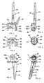
- The drawings illustrate the components of the embodiment, which is for the right wrist joint, by plan and elevational views taken from various aspects as follows:
- Figs. 1, 2 and 3 - the metacarpal component, bearing member and radial component, respectively, from the volar aspect;
- Figs. 4, 5 and 6 - the metacarpal component, bearing member and radial component, respectively, from the radial aspect;
- Figs. 7 and 8 - the metacarpal component from the dorsal and proximal aspects, respectively;
- Figs. 9 - the radial component from the ulnar aspect;
- Fig. 10 - the bearing component from the distal aspect;
- Fig. 11. - the radial component from the distal aspect;
- Fig. 12 - the bearing component from the proximal aspect;
- Fig. 13 - the pin in elevation; and
- Fig. 14 - the sleeve in elevation.
- The prosthesis is intended to reduce pain as much as possible and restore shape and function to relatively severely diseased wrist joints. Generally, the bones of a severely diseased wrist joint are greatly eroded, and some of the carpals may have largely disappeared. The joint will often be considerably foreshortened. Whatever is left of the three medial carpals in each row is surgically removed to make room for the prosthesis, and the distal ends of the radius and ulna are cut away.
- The
radial component 10 of the prosthesis comprises a plate-like portion 12 that replaces the distal anatomical surface at the lower extremity of the radius, astem 14 that tapers proximally from theportion 12 and joins the plate-like portion 12 at the radial edge (i.e., is offset in the radial direction from the center of the portion 12) and aboss 16 that extends distally from the center of the plate-like portion. The nominal plane of the plate-like portion lies oblique to the axis of the stem so that the distal surface faces a few degrees in the volar direction, relative to the stem. This nominal plane defines the limits of extension and flexion, so it is biased toward flexion, relative to the axis of the stem, in correspondence with the normal anatomical wrist joint. - The
boss 16 defines the three axes of articulation of the prosthesis. As in the anatomical wrist joint, the axis of radio-ulnar deviation is offset laterally externally (toward the ulna) from the axis of the radius, and the axis of extension-flexion is offset in the volar direction from the radial axis.. Thestem 14 is received in the distal end of the medullary canal of the radius and is held in place by a surgical cement. Fixation is enhanced by aflat surface 14a on the radial aspect of the stem and agroove 14b on the ulnar aspect. - The
metacarpal component 18 comprises aproximal body portion 20 that is generally U-shaped as viewed in the dorso-volar direction (Figs. 1 and 7) and consists of a pair of laterally spaced-apart legs boss 16 in the assembled prosthesis and abase 20c joining the legs.Stems base 20c and are cemented in place in the second and third metacarpals, respectively. - The U-shaped
body portion 20 of themetacarpal component 18 receives a U-shaped bearingmember 30 made of a rigid surgical-grade polymer, such as ultra high molecular weight polyethylene (UHMWPE). Thelegs notches respective legs boss 40 on the distal surface of thebase 42 of the bearing member nests in a complementarily-shaped recess 20d in themetacarpal base 20c. In the assembled prosthesis, theboss 16 of theradial component 10 is received between thelegs boss 16 has a spherical surface extending along its dorsal, distal and volar aspects that seats in a concavespherical seat 44 in the bearing member. - The components of the prosthesis are connected by a metal pin 46 (Fig. 13) that extends through
holes legs metacarpal component 18 and ahole 52 in theboss 16 of theradial component 10. A sleeve 54 (Fig. 14) of a rigid surgical grade polymer, such as UHMWPE, fits over thepin 46 and intoholes legs member 30. Thepin 46 has anenlarged head 46a that is stopped against the end of thesleeve 54 and is retained by a tiny C-ring (not shown) installed in acircumferential groove 58 in the wall of thehole 50. - The preferred material for the metal components of the prosthesis is Ti-6A1-4V, but other suitable materials can be used.
- The prosthesis affords the following motions of the metacarpal component relative to the radial component:
Flexion-extension occurs by pivoting of the metacarpal component relative to the radial component about the axis of thepin 46 up to about 92° flexion and about 72° extension without restraint. The limits of free flexion-extension are established when the volar and dorsal aspects of the base portion of the bearingmember 30 engage the volar and dorsal edges of thebase portion 12 of the radial component. Thesleeve 54 bears against the distal part of the wall of thehole 52 at both limits of flexure. The elasticity of the sleeve and the bearing member permits several degrees (of arc) of restrained flexion and extension beyond the limits of free flexure; the energy of the forces that produce the additional, restrained movement are absorbed by deformation of the plastic material of the sleeve and the bearing member. - Radio-ulnar deviation is permitted without restraint up to 4° in each direction from neutral by clearances between, first, the
sleeve 54 and thehole 52 in theboss 16 and, second, the convexly arcuate proximal aspects of thelegs conical concavities 12a and 12b on the distal aspect of the carpalarticular portion 12 of the radial component. Laterally outwardly divergentconical surfaces hole 52 in the boss limit angulation of the sleeve in all directions. Engagement of the arcuate end surfaces of the bearingmember legs concavities 12a or 12b provide restraint of radio-ulnar deviation. Several degrees of restrained deviation beyond the limits of free deviation are permitted by deformation of the plastic elements, with energy absorption by such deformation. Deviation is restrained in all positions of flexion and extension and can occur until a few degrees from full flexion and extension. - With the hand fully extended and without radioulnar deviation, compression loads are transmitted from the metacarpal component through the bearing member to the radial component at the region of contact between the spherical surface of the
radial boss 16 and the matchingspherical seat 44 of the bearing member. Upon radio-ulnar deviation in either direction, the arcuate surface of one or the other of theleg portions member 30 engages thecorresponding concavity 12a or 12b of thebase portion 12 of the radial component. Under the compression load, engagement between either of thelegs corresponding surface 12a or 12b will occur without thesleeve 54 engaging the companionconical surface concavities 12a and 12b is offset a small distance proximally from the center axis Y of theconical surfaces sleeve 54 and the conical surfaces in theradial boss 16, and the possibility of loosening of the retention of the radial component due to forces acting on the radial boss is significantly reduced. - Axial rotation of about 8° total without restraint and a few degrees beyond with restraint and energy absorption is permitted by the clearance between the
sleeve 54 and thehole 52 throughout most of the full range of extension and flexion, the unrestrained limits of rotation being established by the cone angles of theconical surfaces hole 52 in theradial boss 16. - There are slight laxities in all directions because of the lateral clearances between the boss and the respective legs of the bearing member and the radial clearance all around between the sleeve and the hole in the boss. The energy-absorption and cushioning effects of the metal-plastic-metal force transfers at the limits of the small translations permitted in all axes reduce the possibility of loss of retention of the prosthesis. The soft tissues of the joint absorb some of the forces that would have to be carried entirely by the prosthesis if there were no laxities.
- The radial component and the metacarpal component are surgically implanted in the patient separately. After the bearing member is placed in its nested position on the metacarpal component, the
sleeve 54 is then inserted through thelarge hole 50 in theleg 20b of the metacarpal component, followed by insertion of thepin 46 and installation of the C-ring (not shown) in thegroove 58.
Claims (5)
- A total wrist joint prosthesis comprising a metal radial component (10) having a stem (14) adapted to be received in the distal portion of the radial medullary canal and secured therein; a plate-like portion (12) adapted to reside at the distal end of the residual anatomical radius, and a boss (16) extending distally from the plate-like portion (12), the boss (16) being offset from the axis of the stem in both the ulnar and volar directions, having a transverse hole (52) and having a spherical surface along its volar, distal and dorsal aspects; a metal metacarpal component (18) having a generally U-shaped body portion composed of laterally spaced-apart legs (20a,20b) that are adapted to straddle the boss of the radial component and a base (20C) interconnecting the legs and having stems (22,24) that extend distally from the base (20C) and are adapted to be received in the proximal portions of the second and third metacarpals and to be secured therein; a metal axle (46) extending between and joined to the legs of the metacarpal component (18) and passing through the hole (52) in the boss (16) of the radial component (10); a sleeve (54) of polymeric material surrounding the portion of the axle within the hole (52), the sleeve (54) being in clearance with the hole (52) to afford constrained radio-ulnar angulation and axial rotation of the metacarpal component (18) relative to the radial component (10); and a generally U-shaped bearing component (30) of a polymeric material received proximally to the boss (16) within the base portion (20C) of the metacarpal component (18), the bearing component (30) having a spherical seat (44) matching and engageable by the spherical surface of the radial boss (16) for flexural articulation of the prosthetic joint and having a dorsal and volar surfaces adapted to engage the dorsal and volar aspects of the plate-like portion (12) of the radial component (10) and in conjunction with engagements between the sleeve (54) and the hole (52) in the boss (16) restrain extension and flexion of the metacarpal component to magnitudes corresponding substantially to those of an anatomical wrist joint, and having convexly curved proximal surfaces that are adapted to engage distal surfaces of the plate-like portion (12) the radial component (10) on either side of the boss to restrain radio-ulnar angulation of the metacarpal component to a magnitude corresponding substantially to those of the anatomical wrist joint.
- A wrist joint prosthesis according to claim 1 wherein the hole (52) in the boss (16) of the radial component (10) includes conical portions (52a,52b) that taper outwardly from the medial to the lateral adjacent each lateral aspect of the boss, thereby to afford radio-ulnar angulation and axial rotation of the prosthetic joint.
- A wrist joint prosthesis according to claim 1 wherein each distal surface of the plate-like portion (12) is a concavity (12a,12b) which is adapted to be engaged by a corresponding one of the convexly curved proximal surfaces of the bearing component (30) to restrain radio-ulnar angulation throughout a substantial range of flexion and extension.
- A wrist joint prosthesis according to claim 3 wherein each of the concavities (12a,12b) slopes laterally and proximally away from the boss (16) at an angle corresponding to the limit of radio-ulnar angulation.
- A wrist joint prosthesis according to claim 3 or claim 4, wherein the distal surfaces of the radial component (10) are arcuate and have a common centerline of curvature, which centerline is spaced apart a small distance distally from the centerline of the transverse hole (52) in the boss (16) of the radial component (10) so that restraint of radio-ulnar angulation under compression is provided predominantly by engagement of said distal and proximal surfaces of the respective radial and bearing components and only secondarily by engagement between the sleeve (54) and the hole (52) in the boss (16).
Applications Claiming Priority (2)
| Application Number | Priority Date | Filing Date | Title |
|---|---|---|---|
| US07/006,984 US4714476A (en) | 1987-01-27 | 1987-01-27 | Wrist joint prosthesis |
| US6984 | 1987-01-27 |
Publications (2)
| Publication Number | Publication Date |
|---|---|
| EP0278318A1 EP0278318A1 (en) | 1988-08-17 |
| EP0278318B1 true EP0278318B1 (en) | 1991-08-14 |
Family
ID=21723588
Family Applications (1)
| Application Number | Title | Priority Date | Filing Date |
|---|---|---|---|
| EP88101098A Expired EP0278318B1 (en) | 1987-01-27 | 1988-01-26 | Wrist joint prosthesis |
Country Status (5)
| Country | Link |
|---|---|
| US (1) | US4714476A (en) |
| EP (1) | EP0278318B1 (en) |
| JP (1) | JP2564346B2 (en) |
| CA (1) | CA1296137C (en) |
| DE (1) | DE3864155D1 (en) |
Families Citing this family (26)
| Publication number | Priority date | Publication date | Assignee | Title |
|---|---|---|---|---|
| CA2078840C (en) * | 1991-09-24 | 1998-08-11 | Alan J. Yeadon | Wrist prothesis |
| DE9316763U1 (en) * | 1993-11-03 | 1994-01-20 | Howmedica GmbH, 24232 Schönkirchen | Endoprosthesis for the proximal wrist |
| DE4406090A1 (en) * | 1994-02-24 | 1995-08-31 | Plus Endoprothetik Ag | Prosthetic wrist |
| US5593445A (en) * | 1995-03-24 | 1997-01-14 | Waits; C. Thomas | Bi-axial prosthetic joint |
| US6673114B2 (en) | 2000-05-03 | 2004-01-06 | Smith & Nephew, Inc. | Multi modular trialing system and instrumentation |
| DE60203787T2 (en) * | 2001-03-02 | 2006-03-09 | Guérard, Jean-Louis | WRIST GRAFT |
| US6953479B2 (en) | 2001-07-16 | 2005-10-11 | Smith & Nephew, Inc. | Orthopedic implant extension |
| US20030187511A1 (en) * | 2002-03-26 | 2003-10-02 | Ball Robert J. | Wrist prosthesis |
| GB2392097A (en) * | 2002-06-29 | 2004-02-25 | Gareth Thomas | Total wrist prosthesis |
| US8105388B2 (en) * | 2002-10-24 | 2012-01-31 | Biomet Manufacturing Corp. | Method and apparatus for wrist arthroplasty |
| US8821581B2 (en) * | 2002-10-24 | 2014-09-02 | Biomet Manufacturing, Llc | Method and apparatus for wrist arthroplasty |
| US8052756B2 (en) * | 2002-10-24 | 2011-11-08 | Biomet Manufacturing Corp. | Method and apparatus for wrist arthroplasty |
| US8105389B2 (en) * | 2002-10-24 | 2012-01-31 | Biomet Manufacturing Corp. | Method and apparatus for wrist arthroplasty |
| US8066777B2 (en) * | 2002-10-24 | 2011-11-29 | Biomet Manufacturing Corp. | Method and apparatus for wrist arthroplasty |
| US6746486B1 (en) * | 2002-10-24 | 2004-06-08 | Biomet, Inc. | Method and apparatus for total wrist angled back carpal plate |
| US8940055B2 (en) | 2002-10-24 | 2015-01-27 | Biomet Manufacturing, Llc | Method and apparatus for wrist arthroplasty |
| US8372154B2 (en) * | 2002-10-24 | 2013-02-12 | Biomet Manufacturing Corp. | Method and apparatus for wrist arthroplasty |
| US8105390B2 (en) * | 2002-10-24 | 2012-01-31 | Biomet Manufacturing Corp. | Method and apparatus for wrist arthroplasty |
| US7625408B2 (en) * | 2003-07-22 | 2009-12-01 | Avanta Orthopaedics, Llc | Prosthetic wrist implant |
| US6969407B2 (en) * | 2003-12-22 | 2005-11-29 | Depuy Products, Inc. | Modular radial component for a total wrist arthroplasty |
| US7160331B2 (en) | 2004-12-01 | 2007-01-09 | Mayo Foundation For Medical Research And Education | Sigmoid notch implant |
| US7608111B2 (en) * | 2006-01-24 | 2009-10-27 | Biomet Manufacturing Corp. | Methods and devices for resurfacing the wrist joint |
| DE602007007095D1 (en) * | 2007-11-07 | 2010-07-22 | Gs Dev Ab | Artificial joint |
| US8152854B2 (en) * | 2009-09-30 | 2012-04-10 | Imbriglia Joseph E | Resurfacing implant for the wrist and method of implantation thereof |
| AU2012253444B2 (en) | 2011-05-12 | 2016-02-18 | Howmedica Osteonics Corp. | Wrist implant for carpal hemiarthroplasty |
| US8852285B2 (en) | 2012-03-13 | 2014-10-07 | Jeffrey A Greenberg | Prosthesis for distal radioulnar joint |
Family Cites Families (7)
| Publication number | Priority date | Publication date | Assignee | Title |
|---|---|---|---|---|
| US4301553A (en) * | 1975-08-15 | 1981-11-24 | United States Surgical Corporation | Prosthetic knee joint |
| US4040130A (en) * | 1976-10-12 | 1977-08-09 | Laure Prosthetics, Inc. | Wrist joint prosthesis |
| US4229840A (en) * | 1978-08-01 | 1980-10-28 | Pfizer Inc. | Total trispherical wrist prosthesis |
| US4229841A (en) * | 1978-11-17 | 1980-10-28 | The University Of Iowa Research Foundation | Wrist prosthesis |
| FR2445137A1 (en) * | 1978-12-29 | 1980-07-25 | Deaux Ets | Knee prosthesis permitting rotary and bending motion - has hinge joint between tibial and femoral components with cammed, profiled surfaces cooperating with tibial stem |
| US4352212A (en) * | 1979-03-05 | 1982-10-05 | Howmedica, Inc. | Joint prosthesis |
| US4307473A (en) * | 1980-02-11 | 1981-12-29 | Weber Edward R | Prosthetic wrist joint |
-
1987
- 1987-01-27 US US07/006,984 patent/US4714476A/en not_active Expired - Lifetime
-
1988
- 1988-01-20 CA CA000556961A patent/CA1296137C/en not_active Expired - Lifetime
- 1988-01-26 JP JP63015708A patent/JP2564346B2/en not_active Expired - Lifetime
- 1988-01-26 DE DE8888101098T patent/DE3864155D1/en not_active Expired - Fee Related
- 1988-01-26 EP EP88101098A patent/EP0278318B1/en not_active Expired
Also Published As
| Publication number | Publication date |
|---|---|
| JP2564346B2 (en) | 1996-12-18 |
| US4714476A (en) | 1987-12-22 |
| EP0278318A1 (en) | 1988-08-17 |
| CA1296137C (en) | 1992-02-25 |
| DE3864155D1 (en) | 1991-09-19 |
| JPS63267355A (en) | 1988-11-04 |
Similar Documents
| Publication | Publication Date | Title |
|---|---|---|
| US4714476A (en) | Wrist joint prosthesis | |
| EP0321927B1 (en) | Elbow joint prosthesis | |
| CA1115454A (en) | Prosthetic joint | |
| US4307473A (en) | Prosthetic wrist joint | |
| EP0854695B1 (en) | Implant device to replace the carpometacarpal joint of the human thumb | |
| AU680559B2 (en) | Joint prosthesis enabling rotary circumduction | |
| EP1633286B1 (en) | Prosthetic device for total joint replacement in small joint arthroplasty | |
| US4352212A (en) | Joint prosthesis | |
| US4204284A (en) | Joint prosthesis with contoured pin | |
| US3991425A (en) | Prosthetic bone joint devices | |
| US5916269A (en) | Wear reduced acetabular component | |
| US4016606A (en) | Knee joint prosthesis | |
| US4224697A (en) | Constrained prosthetic knee | |
| US4231121A (en) | Metacarpal-phalangeal prosthesis | |
| EP1350488A2 (en) | Wrist prosthesis | |
| US4229841A (en) | Wrist prosthesis | |
| EP3914193B1 (en) | Bone joint implants | |
| CA2145217A1 (en) | Prosthetic patello femoral joint assembly | |
| JPS5841857B2 (en) | finger joint prosthesis | |
| US9132019B2 (en) | Metacarpal-phalangeal prosthesis | |
| IE46519B1 (en) | Endoprosthetic joints | |
| WO2004000175A1 (en) | Unicompartmental prosthetic knee joint device | |
| Stauffer | Current status of total ankle replacement | |
| US20210059824A1 (en) | System, apparatus, and method for elbow arthroplasty |
Legal Events
| Date | Code | Title | Description |
|---|---|---|---|
| PUAI | Public reference made under article 153(3) epc to a published international application that has entered the european phase |
Free format text: ORIGINAL CODE: 0009012 |
|
| AK | Designated contracting states |
Kind code of ref document: A1 Designated state(s): BE DE FR GB IT NL SE |
|
| 17P | Request for examination filed |
Effective date: 19890127 |
|
| RIN1 | Information on inventor provided before grant (corrected) |
Inventor name: STRAUB, LEE R. Inventor name: BURSTEIN, ALBERT H. Inventor name: INGLIS, ALLAN E. Inventor name: RANAWAT, CHITRANJAN S. |
|
| R17P | Request for examination filed (corrected) |
Effective date: 19890130 |
|
| 17Q | First examination report despatched |
Effective date: 19901004 |
|
| GRAA | (expected) grant |
Free format text: ORIGINAL CODE: 0009210 |
|
| ITF | It: translation for a ep patent filed | ||
| AK | Designated contracting states |
Kind code of ref document: B1 Designated state(s): BE DE FR GB IT NL SE |
|
| REF | Corresponds to: |
Ref document number: 3864155 Country of ref document: DE Date of ref document: 19910919 |
|
| ET | Fr: translation filed | ||
| PGFP | Annual fee paid to national office [announced via postgrant information from national office to epo] |
Ref country code: GB Payment date: 19920120 Year of fee payment: 5 |
|
| PGFP | Annual fee paid to national office [announced via postgrant information from national office to epo] |
Ref country code: SE Payment date: 19920124 Year of fee payment: 5 |
|
| PGFP | Annual fee paid to national office [announced via postgrant information from national office to epo] |
Ref country code: FR Payment date: 19920125 Year of fee payment: 5 |
|
| PGFP | Annual fee paid to national office [announced via postgrant information from national office to epo] |
Ref country code: DE Payment date: 19920127 Year of fee payment: 5 |
|
| PGFP | Annual fee paid to national office [announced via postgrant information from national office to epo] |
Ref country code: NL Payment date: 19920131 Year of fee payment: 5 |
|
| PGFP | Annual fee paid to national office [announced via postgrant information from national office to epo] |
Ref country code: BE Payment date: 19920212 Year of fee payment: 5 |
|
| PLBE | No opposition filed within time limit |
Free format text: ORIGINAL CODE: 0009261 |
|
| STAA | Information on the status of an ep patent application or granted ep patent |
Free format text: STATUS: NO OPPOSITION FILED WITHIN TIME LIMIT |
|
| 26N | No opposition filed | ||
| PG25 | Lapsed in a contracting state [announced via postgrant information from national office to epo] |
Ref country code: GB Effective date: 19930126 |
|
| PG25 | Lapsed in a contracting state [announced via postgrant information from national office to epo] |
Ref country code: SE Effective date: 19930127 |
|
| PG25 | Lapsed in a contracting state [announced via postgrant information from national office to epo] |
Ref country code: BE Effective date: 19930131 |
|
| BERE | Be: lapsed |
Owner name: NEW YORK SOCIETY FOR THE RELIEF OF THE RUPTURED A Effective date: 19930131 |
|
| PG25 | Lapsed in a contracting state [announced via postgrant information from national office to epo] |
Ref country code: NL Effective date: 19930801 |
|
| NLV4 | Nl: lapsed or anulled due to non-payment of the annual fee | ||
| GBPC | Gb: european patent ceased through non-payment of renewal fee |
Effective date: 19930126 |
|
| PG25 | Lapsed in a contracting state [announced via postgrant information from national office to epo] |
Ref country code: FR Effective date: 19930930 |
|
| PG25 | Lapsed in a contracting state [announced via postgrant information from national office to epo] |
Ref country code: DE Effective date: 19931001 |
|
| REG | Reference to a national code |
Ref country code: FR Ref legal event code: ST |
|
| EUG | Se: european patent has lapsed |
Ref document number: 88101098.7 Effective date: 19930810 |
|
| PG25 | Lapsed in a contracting state [announced via postgrant information from national office to epo] |
Ref country code: IT Free format text: LAPSE BECAUSE OF NON-PAYMENT OF DUE FEES Effective date: 20050126 |