EP0277974B1 - Apparatus for sealing a web of film - Google Patents
Apparatus for sealing a web of film Download PDFInfo
- Publication number
- EP0277974B1 EP0277974B1 EP19870905111 EP87905111A EP0277974B1 EP 0277974 B1 EP0277974 B1 EP 0277974B1 EP 19870905111 EP19870905111 EP 19870905111 EP 87905111 A EP87905111 A EP 87905111A EP 0277974 B1 EP0277974 B1 EP 0277974B1
- Authority
- EP
- European Patent Office
- Prior art keywords
- film
- web
- bars
- jaw
- wing
- Prior art date
- Legal status (The legal status is an assumption and is not a legal conclusion. Google has not performed a legal analysis and makes no representation as to the accuracy of the status listed.)
- Expired - Lifetime
Links
- 238000007789 sealing Methods 0.000 title claims abstract description 25
- 238000010438 heat treatment Methods 0.000 claims description 27
- 230000001154 acute effect Effects 0.000 claims description 3
- 230000008018 melting Effects 0.000 abstract 1
- 238000002844 melting Methods 0.000 abstract 1
- 238000004806 packaging method and process Methods 0.000 description 13
- 229920001971 elastomer Polymers 0.000 description 12
- 239000005060 rubber Substances 0.000 description 12
- 239000012530 fluid Substances 0.000 description 8
- 238000010276 construction Methods 0.000 description 5
- 239000011248 coating agent Substances 0.000 description 3
- 238000000576 coating method Methods 0.000 description 3
- 229910052710 silicon Inorganic materials 0.000 description 3
- 239000010703 silicon Substances 0.000 description 3
- 239000007787 solid Substances 0.000 description 3
- 229910000831 Steel Inorganic materials 0.000 description 2
- 229910052782 aluminium Inorganic materials 0.000 description 2
- XAGFODPZIPBFFR-UHFFFAOYSA-N aluminium Chemical compound [Al] XAGFODPZIPBFFR-UHFFFAOYSA-N 0.000 description 2
- 238000010073 coating (rubber) Methods 0.000 description 2
- 239000003814 drug Substances 0.000 description 2
- 229910001220 stainless steel Inorganic materials 0.000 description 2
- 239000010935 stainless steel Substances 0.000 description 2
- 239000010959 steel Substances 0.000 description 2
- 229910001369 Brass Inorganic materials 0.000 description 1
- RYGMFSIKBFXOCR-UHFFFAOYSA-N Copper Chemical compound [Cu] RYGMFSIKBFXOCR-UHFFFAOYSA-N 0.000 description 1
- 230000015572 biosynthetic process Effects 0.000 description 1
- 239000010951 brass Substances 0.000 description 1
- 239000000919 ceramic Substances 0.000 description 1
- 229910052802 copper Inorganic materials 0.000 description 1
- 239000010949 copper Substances 0.000 description 1
- 238000005536 corrosion prevention Methods 0.000 description 1
- 239000002537 cosmetic Substances 0.000 description 1
- 235000013365 dairy product Nutrition 0.000 description 1
- 229940079593 drug Drugs 0.000 description 1
- 230000000694 effects Effects 0.000 description 1
- 239000013536 elastomeric material Substances 0.000 description 1
- 235000013305 food Nutrition 0.000 description 1
- 239000011810 insulating material Substances 0.000 description 1
- 230000002452 interceptive effect Effects 0.000 description 1
- 239000007788 liquid Substances 0.000 description 1
- 239000000463 material Substances 0.000 description 1
- 229910052751 metal Inorganic materials 0.000 description 1
- 239000002184 metal Substances 0.000 description 1
- 150000002739 metals Chemical class 0.000 description 1
- 238000000034 method Methods 0.000 description 1
- 229920003223 poly(pyromellitimide-1,4-diphenyl ether) Polymers 0.000 description 1
- 238000010408 sweeping Methods 0.000 description 1
- 238000004073 vulcanization Methods 0.000 description 1
- 235000014101 wine Nutrition 0.000 description 1
Images

Classifications
-
- B—PERFORMING OPERATIONS; TRANSPORTING
- B29—WORKING OF PLASTICS; WORKING OF SUBSTANCES IN A PLASTIC STATE IN GENERAL
- B29C—SHAPING OR JOINING OF PLASTICS; SHAPING OF MATERIAL IN A PLASTIC STATE, NOT OTHERWISE PROVIDED FOR; AFTER-TREATMENT OF THE SHAPED PRODUCTS, e.g. REPAIRING
- B29C65/00—Joining or sealing of preformed parts, e.g. welding of plastics materials; Apparatus therefor
- B29C65/02—Joining or sealing of preformed parts, e.g. welding of plastics materials; Apparatus therefor by heating, with or without pressure
- B29C65/18—Joining or sealing of preformed parts, e.g. welding of plastics materials; Apparatus therefor by heating, with or without pressure using heated tools
-
- B—PERFORMING OPERATIONS; TRANSPORTING
- B29—WORKING OF PLASTICS; WORKING OF SUBSTANCES IN A PLASTIC STATE IN GENERAL
- B29C—SHAPING OR JOINING OF PLASTICS; SHAPING OF MATERIAL IN A PLASTIC STATE, NOT OTHERWISE PROVIDED FOR; AFTER-TREATMENT OF THE SHAPED PRODUCTS, e.g. REPAIRING
- B29C65/00—Joining or sealing of preformed parts, e.g. welding of plastics materials; Apparatus therefor
- B29C65/02—Joining or sealing of preformed parts, e.g. welding of plastics materials; Apparatus therefor by heating, with or without pressure
- B29C65/18—Joining or sealing of preformed parts, e.g. welding of plastics materials; Apparatus therefor by heating, with or without pressure using heated tools
- B29C65/24—Joining or sealing of preformed parts, e.g. welding of plastics materials; Apparatus therefor by heating, with or without pressure using heated tools characterised by the means for heating the tool
- B29C65/30—Electrical means
- B29C65/305—Electrical means involving the use of cartridge heaters
-
- B—PERFORMING OPERATIONS; TRANSPORTING
- B29—WORKING OF PLASTICS; WORKING OF SUBSTANCES IN A PLASTIC STATE IN GENERAL
- B29C—SHAPING OR JOINING OF PLASTICS; SHAPING OF MATERIAL IN A PLASTIC STATE, NOT OTHERWISE PROVIDED FOR; AFTER-TREATMENT OF THE SHAPED PRODUCTS, e.g. REPAIRING
- B29C66/00—General aspects of processes or apparatus for joining preformed parts
- B29C66/004—Preventing sticking together, e.g. of some areas of the parts to be joined
- B29C66/0042—Preventing sticking together, e.g. of some areas of the parts to be joined of the joining tool and the parts to be joined
-
- B—PERFORMING OPERATIONS; TRANSPORTING
- B29—WORKING OF PLASTICS; WORKING OF SUBSTANCES IN A PLASTIC STATE IN GENERAL
- B29C—SHAPING OR JOINING OF PLASTICS; SHAPING OF MATERIAL IN A PLASTIC STATE, NOT OTHERWISE PROVIDED FOR; AFTER-TREATMENT OF THE SHAPED PRODUCTS, e.g. REPAIRING
- B29C66/00—General aspects of processes or apparatus for joining preformed parts
- B29C66/01—General aspects dealing with the joint area or with the area to be joined
- B29C66/05—Particular design of joint configurations
- B29C66/10—Particular design of joint configurations particular design of the joint cross-sections
- B29C66/11—Joint cross-sections comprising a single joint-segment, i.e. one of the parts to be joined comprising a single joint-segment in the joint cross-section
- B29C66/112—Single lapped joints
- B29C66/1122—Single lap to lap joints, i.e. overlap joints
-
- B—PERFORMING OPERATIONS; TRANSPORTING
- B29—WORKING OF PLASTICS; WORKING OF SUBSTANCES IN A PLASTIC STATE IN GENERAL
- B29C—SHAPING OR JOINING OF PLASTICS; SHAPING OF MATERIAL IN A PLASTIC STATE, NOT OTHERWISE PROVIDED FOR; AFTER-TREATMENT OF THE SHAPED PRODUCTS, e.g. REPAIRING
- B29C66/00—General aspects of processes or apparatus for joining preformed parts
- B29C66/40—General aspects of joining substantially flat articles, e.g. plates, sheets or web-like materials; Making flat seams in tubular or hollow articles; Joining single elements to substantially flat surfaces
- B29C66/41—Joining substantially flat articles ; Making flat seams in tubular or hollow articles
- B29C66/43—Joining a relatively small portion of the surface of said articles
- B29C66/431—Joining the articles to themselves
- B29C66/4312—Joining the articles to themselves for making flat seams in tubular or hollow articles, e.g. transversal seams
-
- B—PERFORMING OPERATIONS; TRANSPORTING
- B29—WORKING OF PLASTICS; WORKING OF SUBSTANCES IN A PLASTIC STATE IN GENERAL
- B29C—SHAPING OR JOINING OF PLASTICS; SHAPING OF MATERIAL IN A PLASTIC STATE, NOT OTHERWISE PROVIDED FOR; AFTER-TREATMENT OF THE SHAPED PRODUCTS, e.g. REPAIRING
- B29C66/00—General aspects of processes or apparatus for joining preformed parts
- B29C66/80—General aspects of machine operations or constructions and parts thereof
-
- B—PERFORMING OPERATIONS; TRANSPORTING
- B29—WORKING OF PLASTICS; WORKING OF SUBSTANCES IN A PLASTIC STATE IN GENERAL
- B29C—SHAPING OR JOINING OF PLASTICS; SHAPING OF MATERIAL IN A PLASTIC STATE, NOT OTHERWISE PROVIDED FOR; AFTER-TREATMENT OF THE SHAPED PRODUCTS, e.g. REPAIRING
- B29C66/00—General aspects of processes or apparatus for joining preformed parts
- B29C66/80—General aspects of machine operations or constructions and parts thereof
- B29C66/81—General aspects of the pressing elements, i.e. the elements applying pressure on the parts to be joined in the area to be joined, e.g. the welding jaws or clamps
- B29C66/814—General aspects of the pressing elements, i.e. the elements applying pressure on the parts to be joined in the area to be joined, e.g. the welding jaws or clamps characterised by the design of the pressing elements, e.g. of the welding jaws or clamps
- B29C66/8141—General aspects of the pressing elements, i.e. the elements applying pressure on the parts to be joined in the area to be joined, e.g. the welding jaws or clamps characterised by the design of the pressing elements, e.g. of the welding jaws or clamps characterised by the surface geometry of the part of the pressing elements, e.g. welding jaws or clamps, coming into contact with the parts to be joined
- B29C66/81427—General aspects of the pressing elements, i.e. the elements applying pressure on the parts to be joined in the area to be joined, e.g. the welding jaws or clamps characterised by the design of the pressing elements, e.g. of the welding jaws or clamps characterised by the surface geometry of the part of the pressing elements, e.g. welding jaws or clamps, coming into contact with the parts to be joined comprising a single ridge, e.g. for making a weakening line; comprising a single tooth
-
- B—PERFORMING OPERATIONS; TRANSPORTING
- B29—WORKING OF PLASTICS; WORKING OF SUBSTANCES IN A PLASTIC STATE IN GENERAL
- B29C—SHAPING OR JOINING OF PLASTICS; SHAPING OF MATERIAL IN A PLASTIC STATE, NOT OTHERWISE PROVIDED FOR; AFTER-TREATMENT OF THE SHAPED PRODUCTS, e.g. REPAIRING
- B29C66/00—General aspects of processes or apparatus for joining preformed parts
- B29C66/80—General aspects of machine operations or constructions and parts thereof
- B29C66/81—General aspects of the pressing elements, i.e. the elements applying pressure on the parts to be joined in the area to be joined, e.g. the welding jaws or clamps
- B29C66/814—General aspects of the pressing elements, i.e. the elements applying pressure on the parts to be joined in the area to be joined, e.g. the welding jaws or clamps characterised by the design of the pressing elements, e.g. of the welding jaws or clamps
- B29C66/8141—General aspects of the pressing elements, i.e. the elements applying pressure on the parts to be joined in the area to be joined, e.g. the welding jaws or clamps characterised by the design of the pressing elements, e.g. of the welding jaws or clamps characterised by the surface geometry of the part of the pressing elements, e.g. welding jaws or clamps, coming into contact with the parts to be joined
- B29C66/81431—General aspects of the pressing elements, i.e. the elements applying pressure on the parts to be joined in the area to be joined, e.g. the welding jaws or clamps characterised by the design of the pressing elements, e.g. of the welding jaws or clamps characterised by the surface geometry of the part of the pressing elements, e.g. welding jaws or clamps, coming into contact with the parts to be joined comprising a single cavity, e.g. a groove
-
- B—PERFORMING OPERATIONS; TRANSPORTING
- B29—WORKING OF PLASTICS; WORKING OF SUBSTANCES IN A PLASTIC STATE IN GENERAL
- B29C—SHAPING OR JOINING OF PLASTICS; SHAPING OF MATERIAL IN A PLASTIC STATE, NOT OTHERWISE PROVIDED FOR; AFTER-TREATMENT OF THE SHAPED PRODUCTS, e.g. REPAIRING
- B29C66/00—General aspects of processes or apparatus for joining preformed parts
- B29C66/80—General aspects of machine operations or constructions and parts thereof
- B29C66/83—General aspects of machine operations or constructions and parts thereof characterised by the movement of the joining or pressing tools
- B29C66/832—Reciprocating joining or pressing tools
- B29C66/8322—Joining or pressing tools reciprocating along one axis
-
- B—PERFORMING OPERATIONS; TRANSPORTING
- B29—WORKING OF PLASTICS; WORKING OF SUBSTANCES IN A PLASTIC STATE IN GENERAL
- B29C—SHAPING OR JOINING OF PLASTICS; SHAPING OF MATERIAL IN A PLASTIC STATE, NOT OTHERWISE PROVIDED FOR; AFTER-TREATMENT OF THE SHAPED PRODUCTS, e.g. REPAIRING
- B29C66/00—General aspects of processes or apparatus for joining preformed parts
- B29C66/90—Measuring or controlling the joining process
- B29C66/91—Measuring or controlling the joining process by measuring or controlling the temperature, the heat or the thermal flux
- B29C66/912—Measuring or controlling the joining process by measuring or controlling the temperature, the heat or the thermal flux by measuring the temperature, the heat or the thermal flux
- B29C66/9121—Measuring or controlling the joining process by measuring or controlling the temperature, the heat or the thermal flux by measuring the temperature, the heat or the thermal flux by measuring the temperature
- B29C66/91211—Measuring or controlling the joining process by measuring or controlling the temperature, the heat or the thermal flux by measuring the temperature, the heat or the thermal flux by measuring the temperature with special temperature measurement means or methods
- B29C66/91212—Measuring or controlling the joining process by measuring or controlling the temperature, the heat or the thermal flux by measuring the temperature, the heat or the thermal flux by measuring the temperature with special temperature measurement means or methods involving measurement means being part of the welding jaws, e.g. integrated in the welding jaws
-
- B—PERFORMING OPERATIONS; TRANSPORTING
- B29—WORKING OF PLASTICS; WORKING OF SUBSTANCES IN A PLASTIC STATE IN GENERAL
- B29C—SHAPING OR JOINING OF PLASTICS; SHAPING OF MATERIAL IN A PLASTIC STATE, NOT OTHERWISE PROVIDED FOR; AFTER-TREATMENT OF THE SHAPED PRODUCTS, e.g. REPAIRING
- B29C66/00—General aspects of processes or apparatus for joining preformed parts
- B29C66/90—Measuring or controlling the joining process
- B29C66/91—Measuring or controlling the joining process by measuring or controlling the temperature, the heat or the thermal flux
- B29C66/912—Measuring or controlling the joining process by measuring or controlling the temperature, the heat or the thermal flux by measuring the temperature, the heat or the thermal flux
- B29C66/9121—Measuring or controlling the joining process by measuring or controlling the temperature, the heat or the thermal flux by measuring the temperature, the heat or the thermal flux by measuring the temperature
- B29C66/91231—Measuring or controlling the joining process by measuring or controlling the temperature, the heat or the thermal flux by measuring the temperature, the heat or the thermal flux by measuring the temperature of the joining tool
-
- B—PERFORMING OPERATIONS; TRANSPORTING
- B29—WORKING OF PLASTICS; WORKING OF SUBSTANCES IN A PLASTIC STATE IN GENERAL
- B29C—SHAPING OR JOINING OF PLASTICS; SHAPING OF MATERIAL IN A PLASTIC STATE, NOT OTHERWISE PROVIDED FOR; AFTER-TREATMENT OF THE SHAPED PRODUCTS, e.g. REPAIRING
- B29C65/00—Joining or sealing of preformed parts, e.g. welding of plastics materials; Apparatus therefor
- B29C65/74—Joining or sealing of preformed parts, e.g. welding of plastics materials; Apparatus therefor by welding and severing, or by joining and severing, the severing being performed in the area to be joined, next to the area to be joined, in the joint area or next to the joint area
- B29C65/745—Joining or sealing of preformed parts, e.g. welding of plastics materials; Apparatus therefor by welding and severing, or by joining and severing, the severing being performed in the area to be joined, next to the area to be joined, in the joint area or next to the joint area using a single unit having both a severing tool and a welding tool
- B29C65/7451—Joining or sealing of preformed parts, e.g. welding of plastics materials; Apparatus therefor by welding and severing, or by joining and severing, the severing being performed in the area to be joined, next to the area to be joined, in the joint area or next to the joint area using a single unit having both a severing tool and a welding tool the severing tool and the welding tool being movable with respect to one-another
-
- B—PERFORMING OPERATIONS; TRANSPORTING
- B29—WORKING OF PLASTICS; WORKING OF SUBSTANCES IN A PLASTIC STATE IN GENERAL
- B29C—SHAPING OR JOINING OF PLASTICS; SHAPING OF MATERIAL IN A PLASTIC STATE, NOT OTHERWISE PROVIDED FOR; AFTER-TREATMENT OF THE SHAPED PRODUCTS, e.g. REPAIRING
- B29C66/00—General aspects of processes or apparatus for joining preformed parts
- B29C66/80—General aspects of machine operations or constructions and parts thereof
- B29C66/81—General aspects of the pressing elements, i.e. the elements applying pressure on the parts to be joined in the area to be joined, e.g. the welding jaws or clamps
- B29C66/812—General aspects of the pressing elements, i.e. the elements applying pressure on the parts to be joined in the area to be joined, e.g. the welding jaws or clamps characterised by the composition, by the structure, by the intensive physical properties or by the optical properties of the material constituting the pressing elements, e.g. constituting the welding jaws or clamps
- B29C66/8126—General aspects of the pressing elements, i.e. the elements applying pressure on the parts to be joined in the area to be joined, e.g. the welding jaws or clamps characterised by the composition, by the structure, by the intensive physical properties or by the optical properties of the material constituting the pressing elements, e.g. constituting the welding jaws or clamps characterised by the intensive physical properties or by the optical properties of the material constituting the pressing elements, e.g. constituting the welding jaws or clamps
- B29C66/81264—Mechanical properties, e.g. hardness
-
- B—PERFORMING OPERATIONS; TRANSPORTING
- B29—WORKING OF PLASTICS; WORKING OF SUBSTANCES IN A PLASTIC STATE IN GENERAL
- B29C—SHAPING OR JOINING OF PLASTICS; SHAPING OF MATERIAL IN A PLASTIC STATE, NOT OTHERWISE PROVIDED FOR; AFTER-TREATMENT OF THE SHAPED PRODUCTS, e.g. REPAIRING
- B29C66/00—General aspects of processes or apparatus for joining preformed parts
- B29C66/80—General aspects of machine operations or constructions and parts thereof
- B29C66/81—General aspects of the pressing elements, i.e. the elements applying pressure on the parts to be joined in the area to be joined, e.g. the welding jaws or clamps
- B29C66/814—General aspects of the pressing elements, i.e. the elements applying pressure on the parts to be joined in the area to be joined, e.g. the welding jaws or clamps characterised by the design of the pressing elements, e.g. of the welding jaws or clamps
- B29C66/8145—General aspects of the pressing elements, i.e. the elements applying pressure on the parts to be joined in the area to be joined, e.g. the welding jaws or clamps characterised by the design of the pressing elements, e.g. of the welding jaws or clamps characterised by the constructional aspects of the pressing elements, e.g. of the welding jaws or clamps
- B29C66/81457—General aspects of the pressing elements, i.e. the elements applying pressure on the parts to be joined in the area to be joined, e.g. the welding jaws or clamps characterised by the design of the pressing elements, e.g. of the welding jaws or clamps characterised by the constructional aspects of the pressing elements, e.g. of the welding jaws or clamps comprising a block or layer of deformable material, e.g. sponge, foam, rubber
-
- B—PERFORMING OPERATIONS; TRANSPORTING
- B29—WORKING OF PLASTICS; WORKING OF SUBSTANCES IN A PLASTIC STATE IN GENERAL
- B29C—SHAPING OR JOINING OF PLASTICS; SHAPING OF MATERIAL IN A PLASTIC STATE, NOT OTHERWISE PROVIDED FOR; AFTER-TREATMENT OF THE SHAPED PRODUCTS, e.g. REPAIRING
- B29C66/00—General aspects of processes or apparatus for joining preformed parts
- B29C66/80—General aspects of machine operations or constructions and parts thereof
- B29C66/81—General aspects of the pressing elements, i.e. the elements applying pressure on the parts to be joined in the area to be joined, e.g. the welding jaws or clamps
- B29C66/818—General aspects of the pressing elements, i.e. the elements applying pressure on the parts to be joined in the area to be joined, e.g. the welding jaws or clamps characterised by the cooling constructional aspects, or by the thermal or electrical insulating or conducting constructional aspects of the welding jaws or of the clamps ; comprising means for compensating for the thermal expansion of the welding jaws or of the clamps
- B29C66/8182—General aspects of the pressing elements, i.e. the elements applying pressure on the parts to be joined in the area to be joined, e.g. the welding jaws or clamps characterised by the cooling constructional aspects, or by the thermal or electrical insulating or conducting constructional aspects of the welding jaws or of the clamps ; comprising means for compensating for the thermal expansion of the welding jaws or of the clamps characterised by the thermal insulating constructional aspects
- B29C66/81821—General aspects of the pressing elements, i.e. the elements applying pressure on the parts to be joined in the area to be joined, e.g. the welding jaws or clamps characterised by the cooling constructional aspects, or by the thermal or electrical insulating or conducting constructional aspects of the welding jaws or of the clamps ; comprising means for compensating for the thermal expansion of the welding jaws or of the clamps characterised by the thermal insulating constructional aspects of the welding jaws
-
- B—PERFORMING OPERATIONS; TRANSPORTING
- B29—WORKING OF PLASTICS; WORKING OF SUBSTANCES IN A PLASTIC STATE IN GENERAL
- B29K—INDEXING SCHEME ASSOCIATED WITH SUBCLASSES B29B, B29C OR B29D, RELATING TO MOULDING MATERIALS OR TO MATERIALS FOR MOULDS, REINFORCEMENTS, FILLERS OR PREFORMED PARTS, e.g. INSERTS
- B29K2995/00—Properties of moulding materials, reinforcements, fillers, preformed parts or moulds
- B29K2995/0037—Other properties
- B29K2995/007—Hardness
-
- B—PERFORMING OPERATIONS; TRANSPORTING
- B29—WORKING OF PLASTICS; WORKING OF SUBSTANCES IN A PLASTIC STATE IN GENERAL
- B29L—INDEXING SCHEME ASSOCIATED WITH SUBCLASS B29C, RELATING TO PARTICULAR ARTICLES
- B29L2031/00—Other particular articles
- B29L2031/712—Containers; Packaging elements or accessories, Packages
- B29L2031/7148—Blood bags, medical bags
-
- B—PERFORMING OPERATIONS; TRANSPORTING
- B31—MAKING ARTICLES OF PAPER, CARDBOARD OR MATERIAL WORKED IN A MANNER ANALOGOUS TO PAPER; WORKING PAPER, CARDBOARD OR MATERIAL WORKED IN A MANNER ANALOGOUS TO PAPER
- B31B—MAKING CONTAINERS OF PAPER, CARDBOARD OR MATERIAL WORKED IN A MANNER ANALOGOUS TO PAPER
- B31B70/00—Making flexible containers, e.g. envelopes or bags
- B31B70/60—Uniting opposed surfaces or edges; Taping
- B31B70/64—Uniting opposed surfaces or edges; Taping by applying heat or pressure
- B31B70/642—Uniting opposed surfaces or edges; Taping by applying heat or pressure using sealing jaws or sealing dies
-
- Y—GENERAL TAGGING OF NEW TECHNOLOGICAL DEVELOPMENTS; GENERAL TAGGING OF CROSS-SECTIONAL TECHNOLOGIES SPANNING OVER SEVERAL SECTIONS OF THE IPC; TECHNICAL SUBJECTS COVERED BY FORMER USPC CROSS-REFERENCE ART COLLECTIONS [XRACs] AND DIGESTS
- Y10—TECHNICAL SUBJECTS COVERED BY FORMER USPC
- Y10T—TECHNICAL SUBJECTS COVERED BY FORMER US CLASSIFICATION
- Y10T156/00—Adhesive bonding and miscellaneous chemical manufacture
- Y10T156/12—Surface bonding means and/or assembly means with cutting, punching, piercing, severing or tearing
- Y10T156/1378—Cutter actuated by or secured to bonding element
-
- Y—GENERAL TAGGING OF NEW TECHNOLOGICAL DEVELOPMENTS; GENERAL TAGGING OF CROSS-SECTIONAL TECHNOLOGIES SPANNING OVER SEVERAL SECTIONS OF THE IPC; TECHNICAL SUBJECTS COVERED BY FORMER USPC CROSS-REFERENCE ART COLLECTIONS [XRACs] AND DIGESTS
- Y10—TECHNICAL SUBJECTS COVERED BY FORMER USPC
- Y10T—TECHNICAL SUBJECTS COVERED BY FORMER US CLASSIFICATION
- Y10T156/00—Adhesive bonding and miscellaneous chemical manufacture
- Y10T156/17—Surface bonding means and/or assemblymeans with work feeding or handling means
- Y10T156/1702—For plural parts or plural areas of single part
- Y10T156/1712—Indefinite or running length work
- Y10T156/1737—Discontinuous, spaced area, and/or patterned pressing
Definitions
- the present invention relates to an apparatus for sealing a web of film. More specifically, the present invention relates to an apparatus for creating side seals in a web of film in a form, fill and seal packaging machine.
- form, fill and seal packaging machines are utilized to package a product in a flexible container.
- form, fill and seal packaging machines are utilized to seal pharmaceuticals, dairy product, wine, food stuffs, cosmetics and other products in flexible containers.
- the form, fill and seal packaging machine provides an apparatus for packaging these products in an expedient manner.
- fill and seal packaging machine a web of heat-sealable film is passed over a former or mandrel that forms the film into a tubular shape.
- the film is folded longitudinally and heat seal along abutting longitudinal edges.
- the tubular shaped film is then passed around a tubular fill system that deposits the product to be packaged into the tubular shaped film.
- bags To create individual packages (hereinafter "bags") the web of film must be sealed across its width.
- These side seals are typically created by a sealer that creates the second seal for one bag while making the first seal for the next bag. After the side seals are created, the web of film may then be severed between the seals to create individual bags.
- fitments includes, without limitation, ports, valves, and other means for accessing the fluid contained within the container.
- the fitments provide a means for accessing the container either via a spike, needle or valve contained on the fitment.
- the delivery characteristics of the fitment are important. The delivery characteristics are especially important in the medical industry where it is critical that the exact volume of drug prescribed is infused into the patient. Moreover, economic concerns encourage better delivery characteristics. Thus, it is desirable that the deliver characteristics of the bag and fitment are optimum in order to insure that the full contents of the bag are available.
- One way to improve the delivery characteristics of a flexible container is to provide the container with chevrons on its bottom portion.
- the chevrons function to deliver the fluid to the fitment and thereby improve the delivery characteristics of the flexible container.
- the jaws of the sealing apparatus include gripper members that allow the jaws to grip the web of film. Due to the forces and stresses on these gripper members they typically have a high failure rate. Accordingly, the gripper member must be changed at frequent intervals. This can be an especially costly procedure in aseptic form, fill and seal packaging machines wherein the aseptics of the system will be violated during each change.
- DE-B-2528709 discloses the formation in a web of separable gully covers.
- the covers are delineated by Y-shaped seals formed in the web.
- the present invention provides an apparatus for sealing a web of film comprising a first jaw including heating means having side-seal creating means and chevron-seal creating means for contemporaneously creating side seals and chevron seals in the web of film and a second jaw including a back-up member, the first and second jaws being located at opposite sides of the film location, characterised in that the first jaw has wing portions each provided with said chevron-seal creating means and including elastomeric pads for contacting the film, the pads being located adjacent the chevron-seal creating means and raised relative to the heating means.
- the heating means preferably includes a pair of elongated bars for creating the side seals and wing bars extending from each of the elongated bars to create the chevron seals.
- the heating means includes three separate heating zones, the first wing bar being heated by the first heating zone, the second wing bar being heated by a third heating zone, and the elongated bars being heated by the second heating zone.
- An advantage of the present invention is that it provides an improved sealing apparatus suitable for form, fill and seal packaging machines, which may create sealed flexible containers under aseptic conditions, and with which the chevron seals may be created on a web of film that houses a fluid.
- described embodiment of the present invention solidifies a port seating at the end of a bag, made by the apparatus, has rubber grippers that have a substantially longer life than prior art grippers, creates bags that have reduced residual after draining, and is constructed so that the heat from the sealing apparatus is distributed evenly across the chevron seal.
- Figure 1 illustrates a side elevational view of the sealing apparatus of the present invention with the web of film illustrated in broken lines.
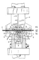
- Figure 2 illustrates a cross-sectional view of the apparatus of Figure 1 sealing a web of film, taken along lines 2-2 of Figure 1.
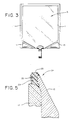
- Figure 3 illustrates a container created on the apparatus of the present invention.
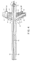
- Figure 4 illustrates a top elevational view of the heating member of the present invention with parts broken away.
- Figure 5 illustrates a cross-sectional view of the gripper member of the apparatus of Figure 1.
- the sealing apparatus 10 of the present invention is illustrated.
- the sealing apparatus 10 is preferably designed for use in a form, fill and seal packaging machine (not shown) to create a container 8 having side seats 11 and chevron sals 13 as illustrated in Figure 3.
- form, fill and seal packaging machine means a machine for creating from a flexible web of film a bag for housing a product.
- fill and seal packaging machine the web of film is folded in half and the side seals are created as the web of film is sealed onto itself.
- the sealing apparatus 10 of the present invention can be used in other packaging machinery or with other apparatus to seal a web of film.
- the sealing apparatus 10 includes a first jaw 12 that includes a heater member 14 and a second jaw 16 that includes the back-up member 18.
- the heating member 14 functions to melt a portion of the web of film 15 so that the side seals 11 and chevron seals 13 are effectuated, and the back-up member 18 functions to urge the web of film 15 against the heating member 14.
- the first jaw 12 and second jaw 15 are located on opposite sides of the web of film 15, diametric each other, i.e., facing each other.
- the jaws 12 and 16 function, in part, to advance the web of film 15 through the sealing stage of the form, fill and seat packaging machine.
- the jaws 12 and 16 are hydraulically actuated and are simultaneously raised and lowered with respect to the web of film 15.
- An automatic advancement of the film 15 is accomplished by intermittently closing and opening the jaws 12 and 16.
- the heater member 14 functions to heat the web of film 15 so that the film is sealed to itself.
- the heater member 14 is secured to the first jaw 12 by thermal insulating blocks 17.
- the thermal insulating blocks 17 are secured to the first jaw 12 by gripper slots (not shown) that clamp the insulating blocks between the jaws.
- the heater member 14 is then clamped between the thermal insulating blocks 17 and held in place by a threaded screw.
- the thermal insulating blocks 17 may be constructed from any high temperature thermal insulating material preferably with usage temperature characteristics in excess of 315°C (600°F). It has been found that a thermal insulating block constructed from Vespel®, by DuPont, functions satisfactorily.
- the heating member 14 includes a hot bar 32.
- the hot bar 32 includes two elongated heater bars 34 and 36 that run the length of the heating member 14. It is the elongated heater bars 34 and 36 that create the side seals 11 in the web or film 15.
- the heater member 14 also includes wing bars 38 and 40 located at acute angles to the heater bars 34 and 36.
- the wing bars 38 and 40 create the chevron seals 13 in the web of flexible film 15.
- the sealing apparatus 10 of the present invention creates the side seals 11 and chevron seals 13 contemporaneously. Accordingly, a separate step is not needed for creating the chevron seals 13.
- each of the wing bars 38 and 40 is located on a wing section 41 and 43 of the heater member 14.
- Each wing section 41 and 43 is a separate heating zone and includes a heater cartridge 49 and 51 respectively.
- the heater cartridges 49 and 51 provide heat to the wing zones 41 and 43 and accordingly heat the wing bars 38 and 40.
- the heater cartridges 49 and 51 are custom wound cartridges. Because they are custom wound to better match the specifics of the applications, the heater cartridges 49 and 51 provide greater control of the temperature. To this end, the heater cartridges 49 and 51 provide two wire temperature control. That is, the element material itself has enough of a coefficient of temperature change resistance to sense temperature change. Accordingly, the heater cartridges 49 and 51 act as thermocouples. Due to the construction of the wing members 41 and 43 it is desirable that the heater cartridges 49 and 51 act as thermocouples because there is no place to locate the thermocouples and get a more accurate reading than where the heater cartridges 49 and 51 are located.
- each wing section 41 and 43 includes thermal pins 45 and 47 respectively.
- the thermal pins 45 and 47 are loacted in apertures in the wing zones 41 and 43.
- the thermal pins 45 and 47 are hollow sealed tubes that include a wick and liquid. The thermal pins insure uniform heat across the wing bars 38 and 40. To this end, the thermal pins are located directly below the wing bars 38 and 40. It has been found that a thermal pin available from Noren of Menlo Park, California, functions satisfactorily for the present invention.
- the elongated heater bars 34 and 36 define a central heating zone 53 is the heater member 14.
- the central heating zone 53 includes a thermocouple 55 and a heater cartridge 57.
- the heater cartridge 57 is an ordinary heater cartridge, it is possible to utilize a two wire temperature control heater cartridge. It is also possible to use a split cartridge, with associated thermocouple, and a thermal pin.
- the proper location for the heater cartridges 49 and 51 for the wing bars 38 and 40 has been found to be a little offset from the center of the wing sections 41 and 43 towards the outside of the wing section; for the elongated heater bars 34 and 36 the proper location for the heater cartridge 57 has been found to be between the elongated heater bars.
- the heating member 14 is constructed from anodized aluminum.
- the aluminum is anodized for corrosion prevention. It is also possible to utilize other metals such as brass, copper, and steel.
- the heater member 14 is of a one-piece construction. This provides better conductivity and is structurally more sound that two or more pieces.
- the sealing surfaces of the elongated heater bars 34 and 36 and wing members 38 and 40 are coated with a release coating.
- the surfaces are coated with a ceramic release coating; an example of such a coating is CERAMIPAK® available from A&A Company of South Plainfiel, New Jersey.
- the wing sections 41 and 43 also include rubber pads 60 and 62.
- the rubber pads 60 and 62 are slightly raised from the remaining surface of the heater member 14.
- the rubber pads 60 and 62 are raised approximately 5/1000 of an inch (0.12 mm) to 15/1000 of an inch (0.38 mm). It has been found that if the rubber pads 60 and 62 are raised by approximately 10/1000 of an inch (0.25 mm) they will function to squeeze any solution away from the area where the chevron seals 13 are to be created.
- the rubbers pads 60 and 62 are constructed from a high temperature, high tear silicon.
- the silicon has a Shore A durometer of 50-70.
- the rubber pads 60 and 62 are vulcanized to the wing sections 41 and 43 and ground to size.
- the rubber pads 60 and 62 are also anchored to the wing sections 41 and 43.
- the wing section can be slotted and the rubber pad anchored therein.
- the rubber pads 60 and 62 also prevent the area under the chevron seals 13 from being sealed. Accordingly, the chevron seals 13 only have a width equal to the width of the wing bars 38 and 40. This is desirable because typically with a solid seal one gets air bubbles; this is due in part to the fluid to be housed by the film. Furthermore, due to the surface area that must be sealed to get a solid seal, a lot of heat must be added to the film. Indeed, a solid seal typically distorts the film.
- the wing bars 38 and 40 extend from the elongated heater bars 34 and 36 at an acute angle. Preferably the angle is approximately 25 to about 35 degrees but can vary depending upon the shape of the chevron desired.
- the wing bars 38 and 40 have a sufficient length so that they extend past the end of the web of film 15. It has been found that the wing bars 38 and 40 can extend past the web of film 15 by approximately 1/2 inch (13 mm) without interfering with the fitments which are attached to the web of film 15.
- the film 15 does not have to be in exact alignment with respect to the wing bars 38 and 40 in order for the chevron seals 13 to be effectuated.
- the alignment of the web of film 15 on the heater member 14 does not have to be perfect. All the critical features are registered at one time, accordingly the web of film 15 does not have to be in perfect alignment.
- the back-up member 18 Located opposite the heater member 14 on a second side of the web of film 15 is the back-up member 18.
- the back-up member 18 is mechanically secured in the second jaw member 16.
- the back-up member 18 is preferably constructed of stainless steel.
- the back-up member 18 functions to urge the web of film 15 against the heater member 14. Accordingly, preferably the whole surface of the back-up member 18 that is in contact with the web of film 15 that is heated by heater member 14 is rubber coated.
- the rubber coating for the back-up member 18 is constructed from a high temperature and high tear silicon and has a Shore A durometer of 50-70. The rubber coating is also preferably vulcanized and anchored to the steel portion of the back-up member.
- the jaws 12 and 16 include gripper members 24 and spring loaded gripper bars 64 respectively.
- the gripper members 24 and spring loaded gripper bars 64 function to clamp the layers of the web of film 15 into intimate contact. This is essential to prevent slippage of the web of film 15 as the sealing apparatus 10 seals the two layers of film together to create the side seals 11 and chevron seals 13.
- the gripper members 24 of the first jaw 12 are preferably constructed from an elastomeric material and include a flat top portion 25 and a body portion 29 respectively.
- the body portions 29 are secured within anchor holes 33 in the jaws 12.
- the anchor holes 33 anchor the gripper members 24 to the jaw 12.
- the gripper members 24 are also vulcanized to the jaw 12. Due to this construction, e.g. because of the flat surfaces 25, anchor holes 33, and vulcanization, the rate of failure for the gripper members 24 is very low. This is in contrast to some prior gripper members for sealing apparatus which cracked or were pulled out of the jaws at relatively frequent intervals.
- the second jaw 16 includes the spring loaded gripper bars 64.
- the spring loaded gripper bars 64 function to grip and advance the web of film 15.
- the sprint loaded gripper bars 64 are constructed from stainless steel with a concave portion for grigging.
- actuated knife Located within the jaw member 16 may be an actuated knife (not shown).
- the actuated knife is designed to sever the web of film 15 between the seals 11.
- the actuated knife is located within a channel 72 defined in the back-up member 18 and the jaw 16.
- the knife is actuated by an air cylinder.
- the knife has a sweeping motion.
- the knife is designed to sever the web of film 15 and be received within a channel 74 defined by the elongated heater bars 34 and 36.
Landscapes
- Engineering & Computer Science (AREA)
- Mechanical Engineering (AREA)
- Physics & Mathematics (AREA)
- Thermal Sciences (AREA)
- Package Closures (AREA)
- Making Paper Articles (AREA)
Abstract
Description
- The present invention relates to an apparatus for sealing a web of film. More specifically, the present invention relates to an apparatus for creating side seals in a web of film in a form, fill and seal packaging machine.
- Typically, form, fill and seal packaging machines are utilized to package a product in a flexible container. To this end, form, fill and seal packaging machines are utilized to seal pharmaceuticals, dairy product, wine, food stuffs, cosmetics and other products in flexible containers. The form, fill and seal packaging machine provides an apparatus for packaging these products in an expedient manner.
- In one type of form, fill and seal packaging machine a web of heat-sealable film is passed over a former or mandrel that forms the film into a tubular shape. To effect a tubular shape, the film is folded longitudinally and heat seal along abutting longitudinal edges. The tubular shaped film is then passed around a tubular fill system that deposits the product to be packaged into the tubular shaped film. To create individual packages (hereinafter "bags") the web of film must be sealed across its width. These side seals are typically created by a sealer that creates the second seal for one bag while making the first seal for the next bag. After the side seals are created, the web of film may then be severed between the seals to create individual bags.
- It is sometimes desirous to create flexible containers filled with fluids that have attached thereto fitments. As used herein the term fitments includes, without limitation, ports, valves, and other means for accessing the fluid contained within the container. The fitments provide a means for accessing the container either via a spike, needle or valve contained on the fitment. Accordingly, the delivery characteristics of the fitment are important. The delivery characteristics are especially important in the medical industry where it is critical that the exact volume of drug prescribed is infused into the patient. Moreover, economic concerns encourage better delivery characteristics. Thus, it is desirable that the deliver characteristics of the bag and fitment are optimum in order to insure that the full contents of the bag are available.
- One way to improve the delivery characteristics of a flexible container is to provide the container with chevrons on its bottom portion. The chevrons function to deliver the fluid to the fitment and thereby improve the delivery characteristics of the flexible container.
- The creation of flexible containers with chevrons has at times been difficult because of the fitments that are attached to the web of film. In flexible containers where chevrons have been used in the past, those containers that have been made in form, fill and seal machines typically have had the chevrons created at a separate station from the side sealing station. Also, when the web of film is utilized to create a container filled with fluid, it has been difficult to put chevrons on the web of film due to the fluid which is housed within the containers.
- Another problem suffered by some prior sealing apparatus is the failure of the gripper members. Typically, the jaws of the sealing apparatus include gripper members that allow the jaws to grip the web of film. Due to the forces and stresses on these gripper members they typically have a high failure rate. Accordingly, the gripper member must be changed at frequent intervals. This can be an especially costly procedure in aseptic form, fill and seal packaging machines wherein the aseptics of the system will be violated during each change.
- Thus, there is a need for an improved sealing apparatus for sealing a web of film and creating chevrons.
- DE-B-2528709 discloses the formation in a web of separable gully covers. The covers are delineated by Y-shaped seals formed in the web.
- The precharacterising part of Claim 1 is based on the disclosure of this document and the distinguishing features of Claim 1 are contained in the characterising part of Claim 1.
- The present invention provides an apparatus for sealing a web of film comprising a first jaw including heating means having side-seal creating means and chevron-seal creating means for contemporaneously creating side seals and chevron seals in the web of film and a second jaw including a back-up member, the first and second jaws being located at opposite sides of the film location, characterised in that the first jaw has wing portions each provided with said chevron-seal creating means and including elastomeric pads for contacting the film, the pads being located adjacent the chevron-seal creating means and raised relative to the heating means.
- The heating means preferably includes a pair of elongated bars for creating the side seals and wing bars extending from each of the elongated bars to create the chevron seals.
- Preferably, the heating means includes three separate heating zones, the first wing bar being heated by the first heating zone, the second wing bar being heated by a third heating zone, and the elongated bars being heated by the second heating zone.
- An advantage of the present invention is that it provides an improved sealing apparatus suitable for form, fill and seal packaging machines, which may create sealed flexible containers under aseptic conditions, and with which the chevron seals may be created on a web of film that houses a fluid. described embodiment of the present invention solidifies a port seating at the end of a bag, made by the apparatus, has rubber grippers that have a substantially longer life than prior art grippers, creates bags that have reduced residual after draining, and is constructed so that the heat from the sealing apparatus is distributed evenly across the chevron seal.
- Additional features and advantages are described in, and will be apparent from, the detailed description of the presently preferred embodiments, and from the drawings.
- Figure 1 illustrates a side elevational view of the sealing apparatus of the present invention with the web of film illustrated in broken lines.
- Figure 2 illustrates a cross-sectional view of the apparatus of Figure 1 sealing a web of film, taken along lines 2-2 of Figure 1.
- Figure 3 illustrates a container created on the apparatus of the present invention.
- Figure 4 illustrates a top elevational view of the heating member of the present invention with parts broken away.
- Figure 5 illustrates a cross-sectional view of the gripper member of the apparatus of Figure 1.
- Referring to Figure 1, the
sealing apparatus 10 of the present invention is illustrated. Thesealing apparatus 10 is preferably designed for use in a form, fill and seal packaging machine (not shown) to create acontainer 8 having side seats 11 andchevron sals 13 as illustrated in Figure 3. - As used herein "form, fill and seal packaging machine" means a machine for creating from a flexible web of film a bag for housing a product. In a typical form, fill and seal packaging machine the web of film is folded in half and the side seals are created as the web of film is sealed onto itself. Of course, the
sealing apparatus 10 of the present invention can be used in other packaging machinery or with other apparatus to seal a web of film. - The
sealing apparatus 10 includes afirst jaw 12 that includes aheater member 14 and asecond jaw 16 that includes the back-upmember 18. As discussed in detail below, and as illustrated in Figure 2, theheating member 14 functions to melt a portion of the web offilm 15 so that the side seals 11 andchevron seals 13 are effectuated, and the back-upmember 18 functions to urge the web offilm 15 against theheating member 14. - As illustrated in Figures 1 and 2, the
first jaw 12 andsecond jaw 15 are located on opposite sides of the web offilm 15, diametric each other, i.e., facing each other. Thejaws film 15 through the sealing stage of the form, fill and seat packaging machine. To this end, thejaws film 15. An automatic advancement of thefilm 15 is accomplished by intermittently closing and opening thejaws - Referring now to Figure 4, the
heater member 14 is illustrated. Theheater member 14 functions to heat the web offilm 15 so that the film is sealed to itself. As illustrated in Figure 1, theheater member 14 is secured to thefirst jaw 12 bythermal insulating blocks 17. Thethermal insulating blocks 17 are secured to thefirst jaw 12 by gripper slots (not shown) that clamp the insulating blocks between the jaws. Theheater member 14 is then clamped between thethermal insulating blocks 17 and held in place by a threaded screw. Thethermal insulating blocks 17 may be constructed from any high temperature thermal insulating material preferably with usage temperature characteristics in excess of 315°C (600°F). It has been found that a thermal insulating block constructed from Vespel®, by DuPont, functions satisfactorily. - The
heating member 14 includes ahot bar 32. Thehot bar 32 includes twoelongated heater bars heating member 14. It is theelongated heater bars film 15. - The
heater member 14 also includeswing bars heater bars flexible film 15. - As illustrated, the sealing
apparatus 10 of the present invention creates the side seals 11 and chevron seals 13 contemporaneously. Accordingly, a separate step is not needed for creating the chevron seals 13. - In order to heat the wing bars 38 and 40, and
elongated bars heater member 14 includes three separate heating zones. To this end, each of the wing bars 38 and 40 is located on awing section heater member 14. Eachwing section heater cartridge heater cartridges wing zones - Preferably, the
heater cartridges heater cartridges heater cartridges heater cartridges wing members heater cartridges heater cartridges - It has been found that a Balco wound cartridge from Heatron Inc. of Kansas City, Missouri, functions satisfactorily. Other heater cartridges that are believed to function satisfactorily are available from Fluid Kinetics of Fairfield, Ohio and Watlow of St. Louis, Missouri.
- To stabilize the temperature distribution of the wing bars 38 and 40, each
wing section thermal pins wing zones - The elongated heater bars 34 and 36 define a
central heating zone 53 is theheater member 14. Thecentral heating zone 53 includes athermocouple 55 and aheater cartridge 57. Although preferably theheater cartridge 57 is an ordinary heater cartridge, it is possible to utilize a two wire temperature control heater cartridge. It is also possible to use a split cartridge, with associated thermocouple, and a thermal pin. Aheater cartridge 57 available from Watlow, St. Louis, Missouri, and athermocouple 55 available from Watlow, St. Louis, Missouri, have been found to function satisfactorily. - Because of the three
heat zones film 15 is filled at the sealing station; this requires that theheater member 14 must deliver more heat in order to create the side seals 11 and chevron seals 13. Moreover, because the web offilm 15 is filled at this station, the temperature of theheater member 14 must be accurately controlled. Theheater cartridges heater cartridges wing sections heater cartridge 57 has been found to be between the elongated heater bars. - The
heating member 14 is constructed from anodized aluminum. The aluminum is anodized for corrosion prevention. It is also possible to utilize other metals such as brass, copper, and steel. Preferably, theheater member 14 is of a one-piece construction. This provides better conductivity and is structurally more sound that two or more pieces. - Preferably, the sealing surfaces of the elongated heater bars 34 and 36 and
wing members - The
wing sections rubber pads rubber pads heater member 14. Preferably, therubber pads rubber pads rubbers pads - The
rubber pads wing sections rubber pads wing sections - Moreover, the
rubber pads - The wing bars 38 and 40 extend from the elongated heater bars 34 and 36 at an acute angle. Preferably the angle is approximately 25 to about 35 degrees but can vary depending upon the shape of the chevron desired. The wing bars 38 and 40 have a sufficient length so that they extend past the end of the web of
film 15. It has been found that the wing bars 38 and 40 can extend past the web offilm 15 by approximately 1/2 inch (13 mm) without interfering with the fitments which are attached to the web offilm 15. - Due to the construction of the wing bars 38 and 40, the
film 15 does not have to be in exact alignment with respect to the wing bars 38 and 40 in order for the chevron seals 13 to be effectuated. Moreover, due to the shape of the wing bars 38 and 40, i.e., because they are straight, and in view of the construction of the elongated heater bars 34 and 36, the alignment of the web offilm 15 on theheater member 14 does not have to be perfect. All the critical features are registered at one time, accordingly the web offilm 15 does not have to be in perfect alignment. - Located opposite the
heater member 14 on a second side of the web offilm 15 is the back-upmember 18. The back-upmember 18 is mechanically secured in thesecond jaw member 16. The back-upmember 18 is preferably constructed of stainless steel. - The back-up
member 18 functions to urge the web offilm 15 against theheater member 14. Accordingly, preferably the whole surface of the back-upmember 18 that is in contact with the web offilm 15 that is heated byheater member 14 is rubber coated. The rubber coating for the back-upmember 18 is constructed from a high temperature and high tear silicon and has a Shore A durometer of 50-70. The rubber coating is also preferably vulcanized and anchored to the steel portion of the back-up member. - To aid in the advancement of the web of
film 15 through the sealing station, thejaws gripper members 24 and spring loaded gripper bars 64 respectively. Thegripper members 24 and spring loaded gripper bars 64 function to clamp the layers of the web offilm 15 into intimate contact. This is essential to prevent slippage of the web offilm 15 as the sealingapparatus 10 seals the two layers of film together to create the side seals 11 and chevron seals 13. - Referring to Figure 5, a cross-sectional view of a
gripper member 24 is illustrated. Thegripper members 24 of thefirst jaw 12 are preferably constructed from an elastomeric material and include a flattop portion 25 and abody portion 29 respectively. Thebody portions 29 are secured within anchor holes 33 in thejaws 12. The anchor holes 33 anchor thegripper members 24 to thejaw 12. Thegripper members 24 are also vulcanized to thejaw 12. Due to this construction, e.g. because of theflat surfaces 25, anchor holes 33, and vulcanization, the rate of failure for thegripper members 24 is very low. This is in contrast to some prior gripper members for sealing apparatus which cracked or were pulled out of the jaws at relatively frequent intervals. - The
second jaw 16 includes the spring loaded gripper bars 64. The spring loaded gripper bars 64 function to grip and advance the web offilm 15. Preferably the sprint loaded gripper bars 64 are constructed from stainless steel with a concave portion for grigging. - Located within the
jaw member 16 may be an actuated knife (not shown). The actuated knife is designed to sever the web offilm 15 between the seals 11. To this end, the actuated knife is located within achannel 72 defined in the back-upmember 18 and thejaw 16. The knife is actuated by an air cylinder. Preferably the knife has a sweeping motion. - The knife is designed to sever the web of
film 15 and be received within achannel 74 defined by the elongated heater bars 34 and 36.
Claims (12)
CHARACTERISED in that the first jaw (12) has wing portions (41,43) each provided with said chevron-seal creating means (38,40) and including elastomeric pads (60,62) for contacting the film (15), the pads being located adjacent the chevron-seal creating means (38,40) and raised relative to the heating means (14).
the means for creating side seal includes a pair of parallel elongated bars (34,36); and
the means for creating chevron seals includes a wing bar (38,40) extending from each of the elongated bars.
a first wing bar (38) is heated by a first of the heating zones (41);
the elongated bars (34,36) are heated by a second of the heating zones (53); and
a second wing bar (40) is heated by a third of the heating zones (43).
the first jaw (12) includes gripper members (24); and
the second jaw (16) includes corresponding spring loaded gripper bars (64).
Applications Claiming Priority (2)
| Application Number | Priority Date | Filing Date | Title |
|---|---|---|---|
| US06/889,713 US4761197A (en) | 1986-07-28 | 1986-07-28 | Apparatus for sealing a web of film |
| US889713 | 1986-07-28 |
Publications (3)
| Publication Number | Publication Date |
|---|---|
| EP0277974A1 EP0277974A1 (en) | 1988-08-17 |
| EP0277974A4 EP0277974A4 (en) | 1989-12-19 |
| EP0277974B1 true EP0277974B1 (en) | 1992-05-20 |
Family
ID=25395652
Family Applications (1)
| Application Number | Title | Priority Date | Filing Date |
|---|---|---|---|
| EP19870905111 Expired - Lifetime EP0277974B1 (en) | 1986-07-28 | 1987-07-23 | Apparatus for sealing a web of film |
Country Status (6)
| Country | Link |
|---|---|
| US (1) | US4761197A (en) |
| EP (1) | EP0277974B1 (en) |
| JP (1) | JP2652181B2 (en) |
| AU (1) | AU600016B2 (en) |
| CA (1) | CA1297766C (en) |
| WO (1) | WO1988000885A1 (en) |
Families Citing this family (47)
| Publication number | Priority date | Publication date | Assignee | Title |
|---|---|---|---|---|
| US5030190A (en) * | 1988-08-24 | 1991-07-09 | The Dow Chemical Company | Gussetted plastic bags having relief seals and method of making same |
| US4856259A (en) * | 1988-10-17 | 1989-08-15 | Baxter International Inc. | Appratus for sealing and severing a web of film |
| US4856260A (en) * | 1988-10-17 | 1989-08-15 | Baxter International Inc. | Apparatus for sealing a web of film in a packaging |
| USD324566S (en) | 1989-03-07 | 1992-03-10 | Baxter International Inc. | Flexible container for medical liquids |
| US4969965A (en) * | 1989-07-03 | 1990-11-13 | Aluminum Company Of America | Using a contoured head for sealing lidding stock |
| DE3923713C2 (en) * | 1989-07-18 | 1993-12-23 | Kallfass Gmbh | Plastic welding device |
| US5248275A (en) * | 1991-05-20 | 1993-09-28 | M & D Balloons, Inc. | Balloon with flat film valve and method of manufacture |
| US5662575A (en) * | 1991-10-16 | 1997-09-02 | Kewpie Kabushiki Kaisha | Method and apparatus for continuously forming bags |
| GB9123445D0 (en) * | 1991-11-05 | 1991-12-18 | Frost F C Ltd | Disposal unit |
| CA2066068C (en) * | 1992-04-15 | 2004-09-28 | Arnold Edward Perrett | Heat sealing jaw assembly |
| GB2267250B (en) * | 1992-05-28 | 1996-01-24 | Food Machinery Design Ltd | Heat seals |
| US5292463A (en) * | 1992-09-03 | 1994-03-08 | General Electric Company | Variable width film die |
| US5632416A (en) * | 1993-01-29 | 1997-05-27 | W. A. Lane, Inc. | Collapsible dispenser pouch |
| US5822955A (en) * | 1993-10-29 | 1998-10-20 | Packaged Ice, Inc. | Grip for a grasping device |
| US5922162A (en) * | 1995-06-07 | 1999-07-13 | Cobe Laboratories, Inc. | Gas-permeable pathogen-resistant labyrinthine seal and method for making labyrinthine seal |
| FR2760723B1 (en) * | 1997-03-13 | 1999-05-14 | Marie Noelle Relecom | STANDING FLEXIBLE POCKET AND DEVICE FOR MAKING SAME |
| JP4021551B2 (en) | 1998-04-27 | 2007-12-12 | 株式会社イシダ | Heat sealing device |
| US6019153A (en) * | 1998-05-08 | 2000-02-01 | The Coe Manufacturing Company | Method and apparatus for joining veneer pieces with lap joint having square cut edges and reduced thickness |
| GB9911813D0 (en) * | 1999-05-21 | 1999-07-21 | British Polythene Ltd | A seal for a sack or bag |
| DE19943492A1 (en) * | 1999-09-10 | 2001-03-15 | Skinetta Pac Syst Kiener Gmbh | Device for separation welding on banding machines |
| IT1313909B1 (en) | 1999-09-29 | 2002-09-26 | Elba Spa | IMPROVED PERFORMANCE SEALING BAR. |
| US6544382B2 (en) | 1999-11-15 | 2003-04-08 | Pactiv Corporation | Apparatus for high-speed heating and cooling of a polymer |
| US6273297B1 (en) | 2000-02-18 | 2001-08-14 | Advanced Food Products, Llc | Dispenser for viscous liquid and flexible viscous liquid containing bag |
| US6668526B2 (en) | 2001-04-27 | 2003-12-30 | Baxter International, Inc. | Web centering system |
| DE20110659U1 (en) * | 2001-06-27 | 2001-09-20 | Schnabel, Werner, 74838 Limbach | Device for the selective connection of plastic strip material |
| US6718735B2 (en) | 2002-03-19 | 2004-04-13 | Baxter International Inc. | Albumin in a flexible polymeric container |
| US20030221773A1 (en) * | 2002-06-04 | 2003-12-04 | Jones Martin T. | Apparatus and method for joining polymeric materials using an electro-magnet |
| US6732492B2 (en) * | 2002-07-23 | 2004-05-11 | Potlatch Corporation | Methods of packaging paper products |
| US6968669B2 (en) * | 2002-11-06 | 2005-11-29 | Lancer Partnership Ltd. | Flexible packaging |
| DE10303178A1 (en) * | 2003-01-28 | 2004-07-29 | Heidelberger Druckmaschinen Ag | Back pressure plate for cardboard box fabrication, has hard anodized surface layer having sufficient thickness and hardness, with grooves formed at predetermined portions of the plate |
| US8124915B2 (en) * | 2003-05-09 | 2012-02-28 | Pregis Intellipack Corporation | Sealing device |
| DE102004038006A1 (en) * | 2004-08-04 | 2006-03-02 | Windmöller & Hölscher Kg | Apparatus and method for producing and filling bags |
| ES2296451B1 (en) * | 2005-06-29 | 2009-05-01 | Eficiencia Y Tecnologia, Effytec, S.A. | PROCEDURE FOR WELDING FLEXIBLE ENVELOPES OF TYPE OVER. |
| TWI286113B (en) * | 2006-02-10 | 2007-09-01 | Hon Hai Prec Ind Co Ltd | Device for packaging and incising plastic wrappers |
| WO2009032763A1 (en) * | 2007-08-28 | 2009-03-12 | Fi-Foil Company, Inc. | A system and method for insulating items using a reflective or inflatable insulation panel |
| US20090097785A1 (en) * | 2007-10-11 | 2009-04-16 | Illinois Tool Works Inc. | Method of producing a hermetic reclosable package using seal bars with non-parallel geometry |
| AT507384B1 (en) * | 2008-09-18 | 2011-07-15 | Westwind Verpackungen Gmbh | CLOSING DEVICE FOR CLOSING PREFERABLY BAGGED PACKAGING UNITS |
| US20110167772A1 (en) | 2010-01-08 | 2011-07-14 | Sealed Air Corporation (Us) | Heat-seal device |
| DE102010048401B4 (en) * | 2010-10-13 | 2013-01-31 | Multivac Sepp Haggenmüller Gmbh & Co. Kg | Method and chamber machine for sealing packaging material |
| US10988293B2 (en) * | 2011-03-17 | 2021-04-27 | The Jel Sert Company | Flexible tubular package for edible product |
| GB2496645B (en) * | 2011-11-17 | 2014-04-09 | Frito Lay Trading Co Gmbh | Packaging apparatus and method of making packages |
| EP2886303A1 (en) * | 2013-12-20 | 2015-06-24 | Multivac Sepp Haggenmüller GmbH & Co. KG | Sealing rail comprising a heat pipe for a packaging machine |
| AU2015315437B2 (en) * | 2014-09-08 | 2020-12-17 | Innoflex Incorporated | Bottom-gusseted package and heat-sealing method |
| CN104175604A (en) * | 2014-09-12 | 2014-12-03 | 江阴市汇通包装机械有限公司 | Splay hot cutter device |
| US10513362B2 (en) * | 2015-03-20 | 2019-12-24 | Dyco, Inc. | Sealing jaws for bagging apparatus |
| DE102017006886A1 (en) * | 2016-08-26 | 2018-03-01 | Kiefel Gmbh | DEVICE FOR EXTENDING A FILM AND FOR WELDING THE FILM TO A CONNECTING PART THAT HAS A MECHANISM AND PROCESS, METHOD OF PRODUCTION, PLANT AND BAG |
| US11565844B2 (en) * | 2018-12-21 | 2023-01-31 | S.C. Johnson & Son, Inc. | Methods and apparatus to facilitate plastic film processing |
Citations (1)
| Publication number | Priority date | Publication date | Assignee | Title |
|---|---|---|---|---|
| WO1986006344A1 (en) * | 1985-04-22 | 1986-11-06 | Inpaco, Inc. | Fitment attachement methods in horizontal form/fill/seal machines |
Family Cites Families (28)
| Publication number | Priority date | Publication date | Assignee | Title |
|---|---|---|---|---|
| NL292488A (en) * | 1962-05-28 | 1900-01-01 | ||
| US3003907A (en) * | 1957-12-02 | 1961-10-10 | Fleur Arthur E La | Machines for making plastic bags |
| NL126868C (en) * | 1962-11-14 | 1900-01-01 | ||
| US3473995A (en) * | 1965-04-19 | 1969-10-21 | Gloucester Eng Co Inc | Web altering mechanism |
| US3488914A (en) * | 1965-05-28 | 1970-01-13 | Fmc Corp | Package filling and sealing system |
| GB1138527A (en) * | 1965-12-11 | 1969-01-01 | Colodense Ltd | Improvements in or relating to the production of sealed filled envelopes |
| US3599387A (en) * | 1969-04-01 | 1971-08-17 | Packaging Frontiers Inc | Form-fill-seal packaging apparatus and methods |
| US3627611A (en) * | 1969-06-25 | 1971-12-14 | Rollprint Packaging Products I | Method and apparatus for the manufacture of surgical pouches |
| US3620884A (en) * | 1969-12-22 | 1971-11-16 | Riegel Paper Corp | Sealing unit for sealing gusset bottom bags |
| US3775225A (en) * | 1971-07-06 | 1973-11-27 | Gloucester Eng Co Inc | Machine for perforating and heat sealing a web including an elongated element with a multiplicity of drivers |
| BE789622A (en) * | 1971-11-12 | 1973-02-01 | Fmc Corp | PROCESS AND APPARATUS FOR MANUFACTURING BAGS OF THERMOPLASTIC MATERIAL WELDED TO THEIR LOWER END |
| US3830681A (en) * | 1972-11-08 | 1974-08-20 | Fmc Corp | Package sealing in steam atmosphere |
| US3845606A (en) * | 1972-11-08 | 1974-11-05 | D Wilson | Package sealing in steam atmosphere |
| US3874976A (en) * | 1973-02-02 | 1975-04-01 | Computron Inc | Gripper jaw assembly |
| US3894381A (en) * | 1973-06-21 | 1975-07-15 | Inpaco | Method and means for attaching fitments to a bag or pouch on a packaging machine |
| US3925139A (en) * | 1974-01-10 | 1975-12-09 | Package Machinery Co | Seal monitoring apparatus |
| US3992981A (en) * | 1975-11-19 | 1976-11-23 | Fmc Corporation | Web stripping apparatus |
| JPS5296172A (en) * | 1976-02-05 | 1977-08-12 | Tokyo Electric Co Ltd | Heat generator for sealing device |
| JPS5839892Y2 (en) * | 1979-01-26 | 1983-09-08 | 株式会社太洋商会 | bag making machine |
| US4221101A (en) * | 1979-02-12 | 1980-09-09 | Fmc Corporation | Apparatus for evacuating and sealing bags |
| DE2946059C2 (en) * | 1979-11-15 | 1986-07-10 | Altstädter Verpackungsvertriebs Gesellschaft mbH, 6102 Pfungstadt | Device for producing packs filled with liquid |
| US4306400A (en) * | 1980-02-07 | 1981-12-22 | Rexham Corporation | Packaging machine with continuous motion top sealer |
| SE423879B (en) * | 1980-10-02 | 1982-06-14 | Flodins Industri Ab | PROCEDURE FOR MANUFACTURING PRODUCTS FROM ONE OR MULTIPLE FILM COATS AND MACHINE FOR IMPLEMENTATION OF THE PROCEDURE |
| DE3118866C2 (en) * | 1981-05-13 | 1984-04-12 | Haver & Boecker, 4740 Oelde | "Machine for filling and closing plastic sacks, preferably gusseted sacks or flat sacks" |
| US4378266A (en) * | 1981-07-29 | 1983-03-29 | Gerken Carl F | Bag sealer |
| IT1145089B (en) * | 1981-09-11 | 1986-11-05 | Mapa Spa | MACHINE FOR MAKING, FILLING AND SEALING BAGS |
| US4512138A (en) * | 1982-03-04 | 1985-04-23 | The Dow Chemical Company | Form, fill and seal machine with hot gas and thermal impulse sealing |
| US4532753A (en) * | 1983-02-18 | 1985-08-06 | Hayssen Manufacturing Company | Method of and apparatus for forming, filling and sealing packages |
-
1986
- 1986-07-28 US US06/889,713 patent/US4761197A/en not_active Expired - Lifetime
-
1987
- 1987-07-23 AU AU77861/87A patent/AU600016B2/en not_active Expired
- 1987-07-23 EP EP19870905111 patent/EP0277974B1/en not_active Expired - Lifetime
- 1987-07-23 JP JP50460187A patent/JP2652181B2/en not_active Expired - Lifetime
- 1987-07-23 WO PCT/US1987/001770 patent/WO1988000885A1/en not_active Ceased
- 1987-07-24 CA CA000542923A patent/CA1297766C/en not_active Expired - Lifetime
Patent Citations (1)
| Publication number | Priority date | Publication date | Assignee | Title |
|---|---|---|---|---|
| WO1986006344A1 (en) * | 1985-04-22 | 1986-11-06 | Inpaco, Inc. | Fitment attachement methods in horizontal form/fill/seal machines |
Also Published As
| Publication number | Publication date |
|---|---|
| EP0277974A4 (en) | 1989-12-19 |
| JP2652181B2 (en) | 1997-09-10 |
| AU7786187A (en) | 1988-02-24 |
| CA1297766C (en) | 1992-03-24 |
| JPH01500417A (en) | 1989-02-16 |
| EP0277974A1 (en) | 1988-08-17 |
| WO1988000885A1 (en) | 1988-02-11 |
| AU600016B2 (en) | 1990-08-02 |
| US4761197A (en) | 1988-08-02 |
Similar Documents
| Publication | Publication Date | Title |
|---|---|---|
| CA1297766C (en) | Apparatus for sealing a web of film | |
| US5247779A (en) | Self voiding jaw for packaging machine | |
| US7866886B2 (en) | Packaging bag with self-closeable outflow port, and method of manufacturing the packaging bag | |
| US6871476B2 (en) | Heat sealing and cutting mechanism and container forming apparatus incorporating the same | |
| EP0210259B1 (en) | Apparatus and method for attaching a fitment to a web of film | |
| EP0400117B1 (en) | Improved apparatus for sealing and severing a web of film | |
| CA1301614C (en) | Apparatus for sealing and severing a web of film | |
| JPS62501902A (en) | Apparatus and method for sealing a web of film in a form, fill and seal packaging system | |
| AU4492289A (en) | Apparatus for sealing a web of film in a packaging machine | |
| CA1314800C (en) | Heat-sealing device for thermoplastic films | |
| US5355656A (en) | Heat sealing element for packaging machines which make lap-sealed pouches | |
| WO1993021001A1 (en) | Heat sealing jaw assembly | |
| EP1795331A1 (en) | Heat seal system for packaging | |
| CA2066066C (en) | Heat sealing element for packaging machines which make lap-sealed pouches | |
| JP2501159B2 (en) | Heat seal roll | |
| RU2798856C2 (en) | Rotary device for pulse welding |
Legal Events
| Date | Code | Title | Description |
|---|---|---|---|
| PUAI | Public reference made under article 153(3) epc to a published international application that has entered the european phase |
Free format text: ORIGINAL CODE: 0009012 |
|
| 17P | Request for examination filed |
Effective date: 19880402 |
|
| AK | Designated contracting states |
Kind code of ref document: A1 Designated state(s): DE FR GB SE |
|
| RAP1 | Party data changed (applicant data changed or rights of an application transferred) |
Owner name: BAXTER INTERNATIONAL INC. (A DELAWARE CORPORATION) |
|
| A4 | Supplementary search report drawn up and despatched |
Effective date: 19891219 |
|
| 17Q | First examination report despatched |
Effective date: 19910306 |
|
| GRAA | (expected) grant |
Free format text: ORIGINAL CODE: 0009210 |
|
| AK | Designated contracting states |
Kind code of ref document: B1 Designated state(s): DE FR GB SE |
|
| REF | Corresponds to: |
Ref document number: 3779291 Country of ref document: DE Date of ref document: 19920625 |
|
| ET | Fr: translation filed | ||
| PLBE | No opposition filed within time limit |
Free format text: ORIGINAL CODE: 0009261 |
|
| STAA | Information on the status of an ep patent application or granted ep patent |
Free format text: STATUS: NO OPPOSITION FILED WITHIN TIME LIMIT |
|
| 26N | No opposition filed | ||
| EAL | Se: european patent in force in sweden |
Ref document number: 87905111.8 |
|
| REG | Reference to a national code |
Ref country code: GB Ref legal event code: IF02 |
|
| PGFP | Annual fee paid to national office [announced via postgrant information from national office to epo] |
Ref country code: FR Payment date: 20060717 Year of fee payment: 20 |
|
| PGFP | Annual fee paid to national office [announced via postgrant information from national office to epo] |
Ref country code: GB Payment date: 20060726 Year of fee payment: 20 |
|
| PGFP | Annual fee paid to national office [announced via postgrant information from national office to epo] |
Ref country code: DE Payment date: 20060831 Year of fee payment: 20 |
|
| REG | Reference to a national code |
Ref country code: GB Ref legal event code: PE20 |
|
| EUG | Se: european patent has lapsed | ||
| PG25 | Lapsed in a contracting state [announced via postgrant information from national office to epo] |
Ref country code: GB Free format text: LAPSE BECAUSE OF EXPIRATION OF PROTECTION Effective date: 20070722 |
|
| PGFP | Annual fee paid to national office [announced via postgrant information from national office to epo] |
Ref country code: SE Payment date: 20060727 Year of fee payment: 20 |