EP0277957B1 - Method of controlling flow resistance in fluid orifice manufacture - Google Patents
Method of controlling flow resistance in fluid orifice manufacture Download PDFInfo
- Publication number
- EP0277957B1 EP0277957B1 EP87902293A EP87902293A EP0277957B1 EP 0277957 B1 EP0277957 B1 EP 0277957B1 EP 87902293 A EP87902293 A EP 87902293A EP 87902293 A EP87902293 A EP 87902293A EP 0277957 B1 EP0277957 B1 EP 0277957B1
- Authority
- EP
- European Patent Office
- Prior art keywords
- orifice
- visco
- flow
- medium
- abrasive
- Prior art date
- Legal status (The legal status is an assumption and is not a legal conclusion. Google has not performed a legal analysis and makes no representation as to the accuracy of the status listed.)
- Expired - Lifetime
Links
- 238000000034 method Methods 0.000 title claims abstract description 36
- 239000012530 fluid Substances 0.000 title claims abstract description 32
- 238000004519 manufacturing process Methods 0.000 title description 5
- 238000012545 processing Methods 0.000 claims description 6
- 238000006073 displacement reaction Methods 0.000 claims description 4
- 238000001125 extrusion Methods 0.000 claims description 4
- 238000005086 pumping Methods 0.000 claims description 3
- 238000003754 machining Methods 0.000 abstract description 31
- 239000004033 plastic Substances 0.000 abstract description 9
- 230000008569 process Effects 0.000 abstract description 8
- 238000012544 monitoring process Methods 0.000 abstract 1
- 239000002245 particle Substances 0.000 description 14
- 239000000463 material Substances 0.000 description 10
- 239000007787 solid Substances 0.000 description 10
- 238000001816 cooling Methods 0.000 description 8
- 239000000446 fuel Substances 0.000 description 8
- 238000012360 testing method Methods 0.000 description 8
- 230000009471 action Effects 0.000 description 7
- 239000007788 liquid Substances 0.000 description 7
- 239000007921 spray Substances 0.000 description 7
- 239000003082 abrasive agent Substances 0.000 description 6
- 238000009760 electrical discharge machining Methods 0.000 description 6
- 230000001276 controlling effect Effects 0.000 description 4
- 238000005553 drilling Methods 0.000 description 4
- 230000009969 flowable effect Effects 0.000 description 4
- 238000005498 polishing Methods 0.000 description 4
- 230000008901 benefit Effects 0.000 description 3
- 238000005266 casting Methods 0.000 description 3
- 230000008859 change Effects 0.000 description 3
- 238000013461 design Methods 0.000 description 3
- 229910052751 metal Inorganic materials 0.000 description 3
- 239000002184 metal Substances 0.000 description 3
- 239000000203 mixture Substances 0.000 description 3
- HBMJWWWQQXIZIP-UHFFFAOYSA-N silicon carbide Chemical compound [Si+]#[C-] HBMJWWWQQXIZIP-UHFFFAOYSA-N 0.000 description 3
- 230000003746 surface roughness Effects 0.000 description 3
- 238000005299 abrasion Methods 0.000 description 2
- 239000006061 abrasive grain Substances 0.000 description 2
- 238000005520 cutting process Methods 0.000 description 2
- 230000000694 effects Effects 0.000 description 2
- 239000007789 gas Substances 0.000 description 2
- 239000011159 matrix material Substances 0.000 description 2
- 238000005259 measurement Methods 0.000 description 2
- 238000002156 mixing Methods 0.000 description 2
- 230000001105 regulatory effect Effects 0.000 description 2
- 229910010271 silicon carbide Inorganic materials 0.000 description 2
- 239000002002 slurry Substances 0.000 description 2
- 229910052580 B4C Inorganic materials 0.000 description 1
- 229910000831 Steel Inorganic materials 0.000 description 1
- 238000007792 addition Methods 0.000 description 1
- 239000003570 air Substances 0.000 description 1
- 230000004075 alteration Effects 0.000 description 1
- PNEYBMLMFCGWSK-UHFFFAOYSA-N aluminium oxide Inorganic materials [O-2].[O-2].[O-2].[Al+3].[Al+3] PNEYBMLMFCGWSK-UHFFFAOYSA-N 0.000 description 1
- INAHAJYZKVIDIZ-UHFFFAOYSA-N boron carbide Chemical compound B12B3B4C32B41 INAHAJYZKVIDIZ-UHFFFAOYSA-N 0.000 description 1
- 238000004364 calculation method Methods 0.000 description 1
- 239000000567 combustion gas Substances 0.000 description 1
- 238000002485 combustion reaction Methods 0.000 description 1
- 230000000052 comparative effect Effects 0.000 description 1
- 239000002173 cutting fluid Substances 0.000 description 1
- 230000003247 decreasing effect Effects 0.000 description 1
- 229910003460 diamond Inorganic materials 0.000 description 1
- 239000010432 diamond Substances 0.000 description 1
- 239000006185 dispersion Substances 0.000 description 1
- 238000009826 distribution Methods 0.000 description 1
- 239000000428 dust Substances 0.000 description 1
- 238000010894 electron beam technology Methods 0.000 description 1
- 239000002657 fibrous material Substances 0.000 description 1
- 239000011888 foil Substances 0.000 description 1
- 239000002223 garnet Substances 0.000 description 1
- 239000011521 glass Substances 0.000 description 1
- 238000002347 injection Methods 0.000 description 1
- 239000007924 injection Substances 0.000 description 1
- 238000005495 investment casting Methods 0.000 description 1
- JEIPFZHSYJVQDO-UHFFFAOYSA-N iron(III) oxide Inorganic materials O=[Fe]O[Fe]=O JEIPFZHSYJVQDO-UHFFFAOYSA-N 0.000 description 1
- 238000011068 loading method Methods 0.000 description 1
- 239000010687 lubricating oil Substances 0.000 description 1
- 150000002739 metals Chemical class 0.000 description 1
- TWNQGVIAIRXVLR-UHFFFAOYSA-N oxo(oxoalumanyloxy)alumane Chemical compound O=[Al]O[Al]=O TWNQGVIAIRXVLR-UHFFFAOYSA-N 0.000 description 1
- 230000035515 penetration Effects 0.000 description 1
- 230000000737 periodic effect Effects 0.000 description 1
- 229920000642 polymer Polymers 0.000 description 1
- 229920001296 polysiloxane Polymers 0.000 description 1
- 238000005070 sampling Methods 0.000 description 1
- 238000005204 segregation Methods 0.000 description 1
- 239000011257 shell material Substances 0.000 description 1
- 238000004513 sizing Methods 0.000 description 1
- 239000010959 steel Substances 0.000 description 1
- 239000004575 stone Substances 0.000 description 1
- 239000000725 suspension Substances 0.000 description 1
- XLYOFNOQVPJJNP-UHFFFAOYSA-N water Substances O XLYOFNOQVPJJNP-UHFFFAOYSA-N 0.000 description 1
- 230000003245 working effect Effects 0.000 description 1
Images

Classifications
-
- B—PERFORMING OPERATIONS; TRANSPORTING
- B24—GRINDING; POLISHING
- B24B—MACHINES, DEVICES, OR PROCESSES FOR GRINDING OR POLISHING; DRESSING OR CONDITIONING OF ABRADING SURFACES; FEEDING OF GRINDING, POLISHING, OR LAPPING AGENTS
- B24B31/00—Machines or devices designed for polishing or abrading surfaces on work by means of tumbling apparatus or other apparatus in which the work and/or the abrasive material is loose; Accessories therefor
- B24B31/10—Machines or devices designed for polishing or abrading surfaces on work by means of tumbling apparatus or other apparatus in which the work and/or the abrasive material is loose; Accessories therefor involving other means for tumbling of work
- B24B31/116—Machines or devices designed for polishing or abrading surfaces on work by means of tumbling apparatus or other apparatus in which the work and/or the abrasive material is loose; Accessories therefor involving other means for tumbling of work using plastically deformable grinding compound, moved relatively to the workpiece under the influence of pressure
-
- B—PERFORMING OPERATIONS; TRANSPORTING
- B23—MACHINE TOOLS; METAL-WORKING NOT OTHERWISE PROVIDED FOR
- B23P—METAL-WORKING NOT OTHERWISE PROVIDED FOR; COMBINED OPERATIONS; UNIVERSAL MACHINE TOOLS
- B23P2700/00—Indexing scheme relating to the articles being treated, e.g. manufactured, repaired, assembled, connected or other operations covered in the subgroups
- B23P2700/06—Cooling passages of turbine components, e.g. unblocking or preventing blocking of cooling passages of turbine components
Definitions
- Fluid flow through orifices is common. Examples include fuel injector nozzle tips, carburetor jets, cooling air flow through turbine engine components, lubricating oil metering for precision bearings and the like. In many such applications, metering of flow rates is of very great importance, but due to manufacturing artifacts, is of very great difficulty. Even very slight variations in manufacturing tolerances can produce substantial variations in flow resistance and flow.
- Parts having fluid flow orifices are made by a wide variety of casting and machining procedures. For example, high quality investment castings are frequently employed for manufacture of such parts. Such parts will have variations in dimensions, particularly wall thicknesses attributable to slight core misalignment or core shifting, and other variations in surface conditions, including surface roughness, pits, nicks, gouges, blow holes, or positive metal. In the extreme, a very slight crack in a core can lead to a thin wall projecting into an internal passage. All these artifacts will substantially impede fluid flow.
- machining methods such as conventional drilling, electrical discharge machining and even less usual techniques as laser, electron beam electrostream, and STEM drilling are not sufficiently precise to avoid the generation of substantial variations in flow resistance.
- electrical discharge machining will not produce perfectly uniform flow resistance since the length of an internal passage may vary as an incident of casting operations, giving rise to fluctuations of hole length and flow resistance despite the uniformity of the hole diameter.
- non-uniform EDM conditions are inevitable and may produce variations in size, shape, surface finish and hole edge conditions.
- injector nozzles are machined with the critical flow metering orifices formed by electrical discharge machining.
- the most critical flow resistance determinants are considered to be the diameter of orifices 10, 11 , and wall thickness at section line A-A, as well as edge condition and surface roughness, including "lay" of the finish.
- the design specifications are for a wall thickness at this point of 0.102 cm + 5.08x10 ⁇ 3cm (0.040 inches + 0.002 inches). Parts outside these specifications are rejected. Accepted parts are segregated in inventory into eight ranges, 6.35x10 ⁇ 4CM (+ 0.00025 inches).
- wall thickness at A-A is an indirect determinant of flow resistance of orifices 10, 11 and that the accurate control of the diameter of orifices 10, 11, is a direct determinant of flow resistance. These parameters determine flow metering properties, and a more direct measure of flow resistance of the part and a direct control in manufacture of such flow resistance is highly desirable.
- FIGs. 3 and 4 Another example of flow resistance through an orifice of significant criticality is the provision of cooling air flow through gas turbine engine components, such as turbine blades.
- gas turbine engine components such as turbine blades.
- investment cast turbine blades are typically cast or drilled (by laser drilling, STEM drilling, or electrical discharge machining), to provide a plurality of holes, typically having a nominal diameter of about 0.025 cm to 0.076 cm (0.010 to 0.030 inches), passing from the interior passage to the vicinity of the leading edge, trailing edge, and elsewhere along the airfoil. Cooling air is forced from the interior, out the plural holes, and into the high temperature combustion gas stream to provide cooling of the blade. Sometimes holes through internal walls of the blade meter the distribution of cooling air.
- U.S. 3,521,412 discloses a method of abrading an internal surface comprising compressively pushing over the surface to be abraded a semi-solid, flowable visco-elastic fluid of the consistency of putty.
- Another object is to provide such method whereby a plurality of flow controlling orifices can be provided with closely matched flow resistance.
- Still another object is to provide method whereby a continuing plurality of parts can be made having predetermined flow resistance with high levels of precision and reproducibility.
- Yet another object is to provide a method of attaining a predetermined flow resistance through an orifice by controlling the operation through a parameter which is a direct determinant of or a direct consequent of flow resistance.
- a further object is to provide parts and components having orifices with reproducible, precise, predetermined flow resistances.
- Still another object is to provide "tuned” turbine engine components.
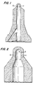
- Fig. 1 is a cross-sectional view of a fuel injector metering nozzle.
- Fig. 2 is an enlarged detail view of a portion of Fig. 1, showing the metering orifices 10, 11.
- Fig. 3 is a cross-sectional view of a turbine blade showing cooling air metering orifices through the leading edge, trailing edge, air foil, and internal walls.
- Fig. 4 is a perspective drawing showing the overall configuration of the turbine blade of Fig. 3.
- Abrasive flow machining is a widely employed procedure for working metals and related materials, particularly for machining and finishing operations on internal shapes, bores, apertures, complex three dimensional shapes, and other difficult operations.
- Abrasive flow is particularly used for deburring, radiusing, re-sizing, and polishing and finishing operations, often in internal shapes which are extremely difficult to process by other machining techniques, including orifices such as those which are the principal concern of the present invention. It is known that flow resistance through an orifice is decreased by abrasive flow machining, and that an orifice can be enlarged by such operations.
- Abrasive flow machining refers to machining operations performed by causing a visco-elastic plastic medium containing abrasive to flow under pressure across the surfaces of a work-piece; wherever flow is restricted, the flow stream is abrasive and performs abrasive work on the work-piece.
- a part or work-piece is fixed in a stationary tool and the abrasive containing visco-elastic plastic medium is hydraulically pumped through the passages formed by the part and its associated tooling at substantial pressure until the desired degree of surface working is performed.
- hydraulic cylinders are employed to pump the medium to the appropriate extent. Areas of the work-piece that do not provide a restriction to flow are largely unworked by the procedure.
- Abrasive flow machining as employed in the present application does not include flow of abrasives suspended or slurried in fluid media such as cutting fluids, honing fluids, gas streams and the like, but rather are limited to semisolid polymer compositions which form stable, non-separating dispersions of solid particulate abrasives which flow by plastic flow or "extrusion.”
- abrasive flow machining tooling is developed to direct and confine the flow of the abrasive medium to take advantage of the foregoing properties and the part or work-piece is subjected to a plurality of cycles determined to be sufficient to perform the desired degree of light machining, normally including deburring, and/or polishing.
- machining is attained with relatively coarse abrasive and polishing with relatively fine abrasive, although in the present context, there is no clear distinction between machining and polishing since a continuum of behavior can be attained from stock removal, leaving a relatively rough and coarse surface finish, to a very low rate or stock removal and a relatively smooth and fine and even highly polished surface finish.
- Abrasive flow machining incorporates the use of a plastic or semi-solid medium containing abrasive particles distributed substantially uniformly throughout.
- the purpose of the semi-solid medium is to transport the abrasive particles to remove the upraised metal and abrade the work-piece as it passes.
- Another purpose of the semi-solid medium is to hold the abrasive particles in suspension so that they will be pressed firmly against the surface of the product when the medium passes through the openings as taught hereinafter, so that the abrasive effect is at a maximum, and uniformly distributed over the surface treated.
- Another purpose of the semi-solid medium is to provide a relatively firm backing for the abrasive, when the medium is under pressure, in order to increase the cutting action of the abrasive against the surface being treated, while still being plastic enough to flow through the product in order to reach all required surfaces.
- liquid slurry carrying abrasive material and pumped through the same kind of work-piece as treated by this invention would not have the required abrasive action nor would it strike all surfaces uniformly.
- Such liquid slurry would require high velocity of flow to provide maximum impingement of the abrasive particles against the surface treated. Under such conditions, some areas would receive no abrasion at all.
- the medium used for abrasive action in abrasive flow machining is a semi-solid, forced through the product under pressure and with relatively low velocity in such a manner as to provide a maximum abrasive action and uniformity of finish. Processes using liquid or air as a medium rely on high velocity and low pressure.
- the semi-solid, difficulty flowable rheopectic medium of abrasive flow machining provides a firm matrix or support for the abrasive particle as it passes over the surface treated.
- the medium for use in this invention is a semi-solid, flowable plastic material uniformly permeated with finely divided abrasive particles, It is necessary to the operation of this invention that the plastic carrier medium have sufficient body at high pressure and low velocity to press the abrasive particles against the surface to be treated with sufficient force to produce the result desired.
- One suitable vehicle for carrying the abrasive particles is silicone putty, i.e., poly (borosiloxane), for example, in the grade indicated by General Electric Company as SS-91. This material has a bounce or rebound of 25 to 50 percent when a twelve gram ball of the putty at 70 to 78 degrees F. is dropped from a height of 254 cm (100 inches) onto a smooth surfaced soapstone block.
- the material has a resilience of 10 percent to 20 percent when measured with a Bashore Resiliometer of the Precision Scientific Company of Chicago, at room temperature and with a special one-half ounce drop weight.
- the same putty has a penetration of 1.5 to 10 mm. in five seconds using a precision Universal Penetrometer with 0.635 cm (one quarter inch) diameter foot on a 47.5 gram test rod with no external loading. This test is made at least twenty-four hours after the batch of putty is dropped or first formed in order to get a reliable test.
- the abrasive used in the carrier putty will be varied to suit the job.
- a satisfactory abrasive for use in working on steel is silicon carbide (SiC), which is readily obtainable in standard grit sizes.
- An abrasive for many applications is aluminum oxide.
- Other abrasives might include diamond dust, boron carbide, rouge, corrundum, garnet, alundum, glass, or in some unusual operations softer material such as fiber or shell material.
- the abrasive per part of rheoplastic putty material will be from about 1/10 part to about ten parts by weight. More typically, it ranges from 1/3 part to 3 parts by weight.
- the honing medium of this invention which acts as a surface abrading tool, is unusual for the reason that the abrasive grain is held or contained in random repositioning arrangement in a plastic matrix.
- the usual concept is that of an abrasive "stone" or lap, wherein the grain particle is fixed and presents one cutting point or edge which is maintained until dulling causes removal by means of a dressing operation.
- the total grain particles, as used in the process of this invention, are sharp until the sum of all points or edges have been exposed many times.
- abrasive flow machining can be directly employed and controlled to govern flow resistance of an orifice by performing an abrasion flow machining operation to a predetermined rate of flow of the abrasive medium through the orifice at constant rate of flow, or other equivalent determinant of the dynamic flow resistance of the orifice being machined. It has been observed that such flow resistance during the working operation is directly correlatable with flow resistance of other fluids through such an orifice, even at greatly different pressure.
- specific values of P o can be targeted by flowing medium at a constant velocity V o and continuing processing until the orifice pressure drops to P o .
- Empirical determination of V o is readily obtained by selecting two prototypical parts having known orifices which provide known rates of flow at the proper pressure with the proper working fluid to be regulated near the target flow rate. By interpolation, these parts are employed as a comparative benchmark to measure V o at P o to establish the predetermined value of V o for use in processing for the chosen abrasive medium.
- V o Q p by definition
- V o k D p /t
- k A p /A o , (approximately constant)
- D p and t are easy to measure to very great precision.
- This determination is based on substantially, constant P p , temperature, abrasive grain size, composition and concentration in the abrasive medium, and constant visco-elastic properties of the abrasive medium. These are all readily maintained within acceptable limits.
- a determination of the target V o and k benchmarks permits matching V o of a multiplicity of pieces to the target by measuring D p and t and computing kD p /t, and continuing the processing until the requisite value is attained. Processing is then terminated, the part is removed and cleaned and has the required V o .
- P p is an independent variable in the abrasive flow machining process and need not be maintained as constant. Indeed, equivalent results can be obtained if D p is maintained constant and P p is varied and measured in the operation or if both P and D p are varied and measured simultaneously. Such operations are equivalent and are considered a part of the present invention.
- the orifice dimensions of the unworked parts be sufficiently undersized so that substantially all the parts need some machining to attain the target V o value. It is particularly preferred that at least about 5 seconds of working time be required is that there is some assurance of steady operating conditions of flow and measurement are assured. This also serves to eliminate rejection of parts for oversize orifices and , since working is continued to the target V o , there will be no parts rejected for undersized orifices either.
- the amount of material to be removed by the abrasive flow machining operation will, in most circumstances, be rather small, involving in most cases an enlargement of the diameter of the orifice on the order of less than a mil or a few mils or in rare instances a few tens of mils. In many cases, the radiusing of the entrance edge of the orifice alone is sufficient to significantly reduce the flow resistance of the orifice. With appropriate selection of the abrasive medium and operating parameters, these operations can be achieved in quite brief operating cycles. Care must be taken that the operating cycle is not so brief that the ability to measure and control is lost.
- the method of the present invention operates to attain a specific dynamic property in the use of the orifice and not specific dimensions. For example, when the length of an orifice is greater that the designed value, due to a core shift in the casting operation for example, it will have a greater flow resistance than a short passage of exactly the same diameter. In the present invention, longer passages will be enlarged more than short ones so that the resulting resistances to flow are equalized. While it is possible to perform abrasive flow machining to dimensioned objectives, such operations are not a part of the present invention.
- THe "test" fluid flow information combined with the initial abrasive media flow rate can be incorporated into an algorithm that will target an abrasive media flow rate that will correspond to the target "test" fluid flow rate.
- the abrasive medium will require periodic replacement in any event, since abraded material will accumulate in the medium and in time begin to increase its viscosity and flow properties. This does not occur rapidly in relation to the number of parts machined, but it does represent a parameter that will require attention.
- Fuel injector spray tips shown in Fig. 1 were obtained.
- One master spray tip was developed having an air flow at 4921.488 gcm ⁇ 2 (70 psig) of 1.770x10⁻⁴m3s1 (0.375 cfm) through 8 orifices disposed at equal angles ⁇ 3 degrees around the periphery of the tip.
- the size of the orifices was 0.017 cm (0.0067 inches), inside diameter.
- the orifices were formed by electrical discharge machining to 0.0060 followed by abrasive flow machining. A total of five hundred additional spary tips conforming to the master were drilled to nominal 0.015 cm (0.0060 inches).
- Tests of twelve spray tips showed a flow rate at 4921.488 gcm ⁇ 2 (70 psig) of 1.484 x 10 ⁇ 4 ⁇ 0.165 x 10 ⁇ 4m3s ⁇ 1 (0.315 cfm ⁇ 0.035 cfm).
- the master spray tip was loaded into a fixture which confined flow through the internal passages, and mounted in an abrasive flow machine.
- the machine was loaded with an abrasive medium comprising poly(borosiloxane) loaded with 1/10 part by weight of silicon carbide, 40 microns, per part of borosiloxane.
- the machine was fitted with a sensor to measure Dp and a timer which were sampled by a microprocessor at a race of one reading each 0.1 seconds and computed V o .
- Flow of the abrasive medium through the master established a reference V o for the medium and pressure employed. This figure was then employed as the reference value for all subsequent spray tips.
- the five-hundred spray tips were then each fitted on the machine and abrasive flow machined to the reference V o .
- the average time to achieve the target V o was 7 seconds.
- the spray tips were then removed form the fixture, cleaned and tested.
- the sample, population showed an air flow at 4921.488 gcm ⁇ 2 (70 psig) of 1.770x10 ⁇ 4 (0.375 cfm) minus 0.014x10 ⁇ 4 m3s ⁇ 1(0.003), plus 0.949x10 ⁇ 8 m s S1 (0.002 cfm).
- Fifty turbine blades having the configuration shown in Fig.4, with a span length of 7.62 cm (3 inches) and a chord of 3.048cm (1.2 inches) were investment cast.
- the master had an air flow at 5273.023 gcm ⁇ 2 (75 psig) of 0.867 m3S ⁇ 1 (1836 cfm); when all but one orifice was blocked, each orifice had an air flow at 5273.023 gcm ⁇ 2 (75 psig) of 4.012x10 ⁇ 3m3s ⁇ 1 (8.5 cfm).
- the remaining turbine blades were laser drilled with the same orifices to a nominal diameter of 0.056 cm (0.022 inches) and then mounted on an abrasive flow machining fixture, mounted in turn in the machine as in Example 1, and machined to the reference V o .
- the blades were then removed, cleaned, and tested at 5273.023 gcm ⁇ 2 (75 psig) and showed an air flow of 6.843x10 ⁇ 3 ⁇ 2.360 x 10 ⁇ 5 m3s ⁇ 1 (14.5 cfm ⁇ 0.05 cfm).
Landscapes
- Engineering & Computer Science (AREA)
- Mechanical Engineering (AREA)
- Finish Polishing, Edge Sharpening, And Grinding By Specific Grinding Devices (AREA)
- Fuel-Injection Apparatus (AREA)
- Electrical Discharge Machining, Electrochemical Machining, And Combined Machining (AREA)
- Grinding And Polishing Of Tertiary Curved Surfaces And Surfaces With Complex Shapes (AREA)
Abstract
Description
- Fluid flow through orifices is common. Examples include fuel injector nozzle tips, carburetor jets, cooling air flow through turbine engine components, lubricating oil metering for precision bearings and the like. In many such applications, metering of flow rates is of very great importance, but due to manufacturing artifacts, is of very great difficulty. Even very slight variations in manufacturing tolerances can produce substantial variations in flow resistance and flow.
- Parts having fluid flow orifices are made by a wide variety of casting and machining procedures. For example, high quality investment castings are frequently employed for manufacture of such parts. Such parts will have variations in dimensions, particularly wall thicknesses attributable to slight core misalignment or core shifting, and other variations in surface conditions, including surface roughness, pits, nicks, gouges, blow holes, or positive metal. In the extreme, a very slight crack in a core can lead to a thin wall projecting into an internal passage. All these artifacts will substantially impede fluid flow.
- Commonly employed machining methods, such as conventional drilling, electrical discharge machining and even less usual techniques as laser, electron beam electrostream, and STEM drilling are not sufficiently precise to avoid the generation of substantial variations in flow resistance. Probably, the most precise of these, electrical discharge machining, will not produce perfectly uniform flow resistance since the length of an internal passage may vary as an incident of casting operations, giving rise to fluctuations of hole length and flow resistance despite the uniformity of the hole diameter. In addition, non-uniform EDM conditions are inevitable and may produce variations in size, shape, surface finish and hole edge conditions.
- At present, such deviations are necessarily tolerated with broad limits and the attendant compromises in design freedom, performance, and efficiency are accepted as unavoidable. For example, the delivery of fuel charges to internal combustion engines by pressurized fuel injection requires metering of flow through injectors. The more precisely the flow can be regulated, the greater will be the fuel efficiency and economy of the engine operation. At present, the design of such fuel metering systems is often based on measurement of actual flow resistance and segregation of inventories within ranges of flow parameters to provide at least approximate matching of components in inventory within a range of deviation from defined tolerances. Such operations are a considerable expense because of the substantial inventory requirements. In addition, a substantial number of components must be rejected as out of allowable deviations and must be reworked at considerable expense or discarded.
- At the present time, injector nozzles are machined with the critical flow metering orifices formed by electrical discharge machining. As shown in Fig. 1, the most critical flow resistance determinants are considered to be the diameter of
orifices 10, 11 , and wall thickness at section line A-A, as well as edge condition and surface roughness, including "lay" of the finish. The design specifications are for a wall thickness at this point of 0.102 cm + 5.08x10⁻³cm (0.040 inches + 0.002 inches). Parts outside these specifications are rejected. Accepted parts are segregated in inventory into eight ranges, 6.35x10⁻⁴CM (+ 0.00025 inches). Those of ordinary skill in the art have long been aware that wall thickness at A-A is an indirect determinant of flow resistance oforifices 10, 11 and that the accurate control of the diameter oforifices 10, 11, is a direct determinant of flow resistance. These parameters determine flow metering properties, and a more direct measure of flow resistance of the part and a direct control in manufacture of such flow resistance is highly desirable. - Another example of flow resistance through an orifice of significant criticality is the provision of cooling air flow through gas turbine engine components, such as turbine blades. As shown in Figs. 3 and 4, investment cast turbine blades are typically cast or drilled (by laser drilling, STEM drilling, or electrical discharge machining), to provide a plurality of holes, typically having a nominal diameter of about 0.025 cm to 0.076 cm (0.010 to 0.030 inches), passing from the interior passage to the vicinity of the leading edge, trailing edge, and elsewhere along the airfoil. Cooling air is forced from the interior, out the plural holes, and into the high temperature combustion gas stream to provide cooling of the blade. Sometimes holes through internal walls of the blade meter the distribution of cooling air. It is reasonable apparent that variations in flow resistance can result in different cooling effects which can result in hot spots which may alter the heat balance within the components and the engine itself and affect both performance and component life. Cooling air usage should however be minimized as its excessive usage reduces engine efficiency by "stealing" compressor section energy.. More precise control of flow resistance of these orifices can provide substantial benefits in operation of such components and of the units into which they are assembled.
- There are numerous other examples of flow control orifices to which the present invention is applicable, but the foregoing examples show representative examples which serve to illustrate the state of the art and the problem addressed and solved by the present invention.
- U.S. 3,521,412 discloses a method of abrading an internal surface comprising compressively pushing over the surface to be abraded a semi-solid, flowable visco-elastic fluid of the consistency of putty.
- It is an object of the present invention to provide a method of working flow controlling orifices in structures to attain a precise flow resistance.
- It is a further object to provide such a method to provide a precise predetermined flow resistance.
- Another object is to provide such method whereby a plurality of flow controlling orifices can be provided with closely matched flow resistance.
- Still another object is to provide method whereby a continuing plurality of parts can be made having predetermined flow resistance with high levels of precision and reproducibility.
- Yet another object is to provide a method of attaining a predetermined flow resistance through an orifice by controlling the operation through a parameter which is a direct determinant of or a direct consequent of flow resistance.
- A further object is to provide parts and components having orifices with reproducible, precise, predetermined flow resistances.
- Still another object is to provide "tuned" turbine engine components.
- These objects can be achieved by a method according to claim 1 or claim 9, respectively.
- Fig. 1 is a cross-sectional view of a fuel injector metering nozzle.
- Fig. 2 is an enlarged detail view of a portion of Fig. 1, showing the
metering orifices 10, 11. - Fig. 3 is a cross-sectional view of a turbine blade showing cooling air metering orifices through the leading edge, trailing edge, air foil, and internal walls.
- Fig. 4 is a perspective drawing showing the overall configuration of the turbine blade of Fig. 3.
- Abrasive flow machining is a widely employed procedure for working metals and related materials, particularly for machining and finishing operations on internal shapes, bores, apertures, complex three dimensional shapes, and other difficult operations.
- Abrasive flow is particularly used for deburring, radiusing, re-sizing, and polishing and finishing operations, often in internal shapes which are extremely difficult to process by other machining techniques, including orifices such as those which are the principal concern of the present invention. It is known that flow resistance through an orifice is decreased by abrasive flow machining, and that an orifice can be enlarged by such operations.
- Abrasive flow machining as employed in the present application refers to machining operations performed by causing a visco-elastic plastic medium containing abrasive to flow under pressure across the surfaces of a work-piece; wherever flow is restricted, the flow stream is abrasive and performs abrasive work on the work-piece. Typically, a part or work-piece is fixed in a stationary tool and the abrasive containing visco-elastic plastic medium is hydraulically pumped through the passages formed by the part and its associated tooling at substantial pressure until the desired degree of surface working is performed. Typically, hydraulic cylinders are employed to pump the medium to the appropriate extent. Areas of the work-piece that do not provide a restriction to flow are largely unworked by the procedure. Abrasive flow machining as employed in the present application does not include flow of abrasives suspended or slurried in fluid media such as cutting fluids, honing fluids, gas streams and the like, but rather are limited to semisolid polymer compositions which form stable, non-separating dispersions of solid particulate abrasives which flow by plastic flow or "extrusion."
- In the usual application of abrasive flow machining, tooling is developed to direct and confine the flow of the abrasive medium to take advantage of the foregoing properties and the part or work-piece is subjected to a plurality of cycles determined to be sufficient to perform the desired degree of light machining, normally including deburring, and/or polishing. Generally speaking, machining is attained with relatively coarse abrasive and polishing with relatively fine abrasive, although in the present context, there is no clear distinction between machining and polishing since a continuum of behavior can be attained from stock removal, leaving a relatively rough and coarse surface finish, to a very low rate or stock removal and a relatively smooth and fine and even highly polished surface finish. By taking advantage of combinations of media and extrusion pressures and rates, substantially any combination of abrasive working properties can be attained.
- Abrasive flow machining incorporates the use of a plastic or semi-solid medium containing abrasive particles distributed substantially uniformly throughout. The purpose of the semi-solid medium is to transport the abrasive particles to remove the upraised metal and abrade the work-piece as it passes.
- Another purpose of the semi-solid medium is to hold the abrasive particles in suspension so that they will be pressed firmly against the surface of the product when the medium passes through the openings as taught hereinafter, so that the abrasive effect is at a maximum, and uniformly distributed over the surface treated.
- Another purpose of the semi-solid medium is to provide a relatively firm backing for the abrasive, when the medium is under pressure, in order to increase the cutting action of the abrasive against the surface being treated, while still being plastic enough to flow through the product in order to reach all required surfaces.
- It should be noted that a liquid slurry carrying abrasive material and pumped through the same kind of work-piece as treated by this invention would not have the required abrasive action nor would it strike all surfaces uniformly. Such liquid slurry would require high velocity of flow to provide maximum impingement of the abrasive particles against the surface treated. Under such conditions, some areas would receive no abrasion at all.
- Some differences between the medium used for abrasive action in abrasive flow machining and those employing abrasive carried by a liquid or air or gaseous medium should be noted. In abrasive flow machining, the medium used is a semi-solid, forced through the product under pressure and with relatively low velocity in such a manner as to provide a maximum abrasive action and uniformity of finish. Processes using liquid or air as a medium rely on high velocity and low pressure. The semi-solid, difficulty flowable rheopectic medium of abrasive flow machining provides a firm matrix or support for the abrasive particle as it passes over the surface treated. Other processes using liquid or air as a medium or vehicle rely on high velocity and impingement of the abrasive particle against the work-piece. Sharp corners requiring blending usually occur at a conjunction of two surfaces. Flow through or past the product, therefore, changes direction of these points. A change of direction of flow of the present semi-solid, difficulty flowable medium, tends to increase the abrasive action in the present process at such conjunction or surfaces. A liquid or air medium, on the other hand, carrying abrasive particles, will tend toward reduced abrasive action at these points of change of direction, and, under high velocity, the turbulent flow used with such liquid and air mediums tends to create areas of no particle motion, at points of changing direction, resulting in no abrasive action at these points.
- The medium for use in this invention is a semi-solid, flowable plastic material uniformly permeated with finely divided abrasive particles, It is necessary to the operation of this invention that the plastic carrier medium have sufficient body at high pressure and low velocity to press the abrasive particles against the surface to be treated with sufficient force to produce the result desired. One suitable vehicle for carrying the abrasive particles is silicone putty, i.e., poly (borosiloxane), for example, in the grade indicated by General Electric Company as SS-91. This material has a bounce or rebound of 25 to 50 percent when a twelve gram ball of the putty at 70 to 78 degrees F. is dropped from a height of 254 cm (100 inches) onto a smooth surfaced soapstone block. The material has a resilience of 10 percent to 20 percent when measured with a Bashore Resiliometer of the Precision Scientific Company of Chicago, at room temperature and with a special one-half ounce drop weight. The same putty has a penetration of 1.5 to 10 mm. in five seconds using a precision Universal Penetrometer with 0.635 cm (one quarter inch) diameter foot on a 47.5 gram test rod with no external loading. This test is made at least twenty-four hours after the batch of putty is dropped or first formed in order to get a reliable test.
- Obviously, the abrasive used in the carrier putty will be varied to suit the job. A satisfactory abrasive for use in working on steel is silicon carbide (SiC), which is readily obtainable in standard grit sizes. An abrasive for many applications is aluminum oxide. Other abrasives might include diamond dust, boron carbide, rouge, corrundum, garnet, alundum, glass, or in some unusual operations softer material such as fiber or shell material. Commonly, the abrasive per part of rheoplastic putty material will be from about 1/10 part to about ten parts by weight. More typically, it ranges from 1/3 part to 3 parts by weight.
- It is necessary to hold the work-piece so as to confine the flow of the honing medium past the area to be treated. In the case of an opening through the work-piece, special adapters or tooling may be required to pass the honing medium into a certain opening and out of a certain opening in the work-piece. This is merely the skill of the industry.
- The honing medium of this invention, which acts as a surface abrading tool, is unusual for the reason that the abrasive grain is held or contained in random repositioning arrangement in a plastic matrix. The usual concept is that of an abrasive "stone" or lap, wherein the grain particle is fixed and presents one cutting point or edge which is maintained until dulling causes removal by means of a dressing operation. The total grain particles, as used in the process of this invention, are sharp until the sum of all points or edges have been exposed many times.
- Heretofore, it has been usual to employ a fixed number of cycles of such abrasive flow at a fixed pumping cylinder pressure and a fixed volume or abrasive medium to perform an abrasive flow working operation. Such parameters are ordinarily determined empirically for a given work-piece and tooling combination to provide suitable results.
- It should be noted that within a given flow path, localized changes in flow resistance will be created by localized perturbations in cross-section so that burrs, flashings and other projections of material into the flow path will preferentially removed. This makes abrasive flow machining particularly effective for deburring parts and work-pieces, and particularly those with internal passages and bores which cannot effectively be dealt with by other more traditional techniques. Abrasive flow machining has indeed been used for deburring in many cases involving flow controlling orifices as well as other work-pieces.
- It has been discovered that in addition to all the foregoing features and uses, abrasive flow machining can be directly employed and controlled to govern flow resistance of an orifice by performing an abrasion flow machining operation to a predetermined rate of flow of the abrasive medium through the orifice at constant rate of flow, or other equivalent determinant of the dynamic flow resistance of the orifice being machined. It has been observed that such flow resistance during the working operation is directly correlatable with flow resistance of other fluids through such an orifice, even at greatly different pressure.
- In the following discussion, the following terms are employed:
- t
- = Time at flow rate
- Ap
- = Piston Area
- Pp
- = Piston pressure applied to abrasive media
- Dp
- = Piston axial displacement distance
- Vp
- =

- Qp
- =

- Ao
- = Orifice area
- Po
- = Orifice pressure
- Do
- = Orifice axial distance of medium flow
- Vo
- = Orifice velocity (rate) of flow of abrasive medium
- Qo
- = Orifice volume of flow
- Alternatively, specific values of Po can be targeted by flowing medium at a constant velocity Vo and continuing processing until the orifice pressure drops to Po.
- Empirical determination of Vo is readily obtained by selecting two prototypical parts having known orifices which provide known rates of flow at the proper pressure with the proper working fluid to be regulated near the target flow rate. By interpolation, these parts are employed as a comparative benchmark to measure Vo at Po to establish the predetermined value of Vo for use in processing for the chosen abrasive medium.
- Actual values of Vo are determined in accordance with the following considerations in the case of a single orifice:


where
Both Dp and t are easy to measure to very great precision. Since k is a parameter which is approximately constant, as Ao changes very slightly as the process proceeds, it is effective to treat k as a constant where the time interval, t, is small. This approximation is quite valid for time intervals, t, of less than about one second. In practice, it is often convenient to use sampling rates at an interval of t = 0.1 seconds or smaller. - This determination is based on substantially, constant Pp, temperature, abrasive grain size, composition and concentration in the abrasive medium, and constant visco-elastic properties of the abrasive medium. These are all readily maintained within acceptable limits.
- In operation, then, a determination of the target Vo and k benchmarks permits matching Vo of a multiplicity of pieces to the target by measuring Dp and t and computing kDp/t, and continuing the processing until the requisite value is attained. Processing is then terminated, the part is removed and cleaned and has the required Vo.
- As those of ordinary skill in the art will appreciate, Pp is an independent variable in the abrasive flow machining process and need not be maintained as constant. Indeed, equivalent results can be obtained if Dp is maintained constant and Pp is varied and measured in the operation or if both P and Dp are varied and measured simultaneously. Such operations are equivalent and are considered a part of the present invention.
- When multiple orifices in a single part or multiple parts are to be processed in parallel, simultaneous abrasive flow machining, the considerations are essentially the same.
- Indeed, it is generally preferred that the orifice dimensions of the unworked parts be sufficiently undersized so that substantially all the parts need some machining to attain the target Vo value. It is particularly preferred that at least about 5 seconds of working time be required is that there is some assurance of steady operating conditions of flow and measurement are assured. This also serves to eliminate rejection of parts for oversize orifices and , since working is continued to the target Vo, there will be no parts rejected for undersized orifices either.
- The amount of material to be removed by the abrasive flow machining operation will, in most circumstances, be rather small, involving in most cases an enlargement of the diameter of the orifice on the order of less than a mil or a few mils or in rare instances a few tens of mils. In many cases, the radiusing of the entrance edge of the orifice alone is sufficient to significantly reduce the flow resistance of the orifice. With appropriate selection of the abrasive medium and operating parameters, these operations can be achieved in quite brief operating cycles. Care must be taken that the operating cycle is not so brief that the ability to measure and control is lost.
- It is important to recognize that the method of the present invention operates to attain a specific dynamic property in the use of the orifice and not specific dimensions. For example, when the length of an orifice is greater that the designed value, due to a core shift in the casting operation for example, it will have a greater flow resistance than a short passage of exactly the same diameter. In the present invention, longer passages will be enlarged more than short ones so that the resulting resistances to flow are equalized. While it is possible to perform abrasive flow machining to dimensioned objectives, such operations are not a part of the present invention.
- The influence of various orifice conditions on the flow rate of abrasive media may vary from that of the fluid the orifice is intended to meter. For instance, surface roughness, edge radius, and orifice diameter and length may affect flow differently than air, water, or fuel. Consequently, quantifying the orifice with the appropriate "test" fluid before abrasive flow machining may be desirable. THe "test" fluid flow information combined with the initial abrasive media flow rate can be incorporated into an algorithm that will target an abrasive media flow rate that will correspond to the target "test" fluid flow rate.
- In the application of the present procedure to small orifices on the order of up to about 0.025 cm (0.010 inches) it is generally desireable to employ rather fine abrasive particles, on the order of 600 to 1200 mesh and less. This will result in better control of the extent and rate of material removal form the work-piece and leave a finer surface finish than would be attained with coarser abrasives. For larger orifices, proportionately larger grain sizes would be more effective, particularly when substantial alterations in flow rate are required. It is also preferred to use hard abrasive, typically silicon carbide, to minimize the change in abrasive properties over a large number of process cycles. Use of softer abrasives may require relatively frequent replacement of the abrasive medium. The abrasive medium will require periodic replacement in any event, since abraded material will accumulate in the medium and in time begin to increase its viscosity and flow properties. This does not occur rapidly in relation to the number of parts machined, but it does represent a parameter that will require attention.
- Frequent additions of a small percentage of "new" abrasive media combined with a blending operation to uniformly distribute the "new" media within the "old" can keep the mixture at a constant homogeneous condition. This can be done either manually or automatically.
- Fuel injector spray tips shown in Fig. 1 were obtained. One master spray tip was developed having an air flow at 4921.488 gcm⁻² (70 psig) of 1.770x10-⁴m³s¹ (0.375 cfm) through 8 orifices disposed at equal angles ± 3 degrees around the periphery of the tip. The size of the orifices was 0.017 cm (0.0067 inches), inside diameter. The orifices were formed by electrical discharge machining to 0.0060 followed by abrasive flow machining. A total of five hundred additional spary tips conforming to the master were drilled to nominal 0.015 cm (0.0060 inches). Tests of twelve spray tips showed a flow rate at 4921.488 gcm⁻² (70 psig) of 1.484 x 10⁻⁴ ± 0.165 x 10⁻⁴m³s⁻¹ (0.315 cfm ± 0.035 cfm).
- The master spray tip was loaded into a fixture which confined flow through the internal passages, and mounted in an abrasive flow machine. The machine was loaded with an abrasive medium comprising poly(borosiloxane) loaded with 1/10 part by weight of silicon carbide, 40 microns, per part of borosiloxane.
- The machine was fitted with a sensor to measure Dp and a timer which were sampled by a microprocessor at a race of one reading each 0.1 seconds and computed Vo. Flow of the abrasive medium through the master established a reference Vo for the medium and pressure employed. This figure was then employed as the reference value for all subsequent spray tips.
- The five-hundred spray tips were then each fitted on the machine and abrasive flow machined to the reference Vo. The average time to achieve the target Vo was 7 seconds. The spray tips were then removed form the fixture, cleaned and tested. The sample, population showed an air flow at 4921.488 gcm⁻² (70 psig) of 1.770x10⁻⁴ (0.375 cfm) minus 0.014x10⁻⁴ m³s⁻¹(0.003), plus 0.949x10⁻⁸ msS¹ (0.002 cfm).
- Fifty turbine blades having the configuration shown in Fig.4, with a span length of 7.62 cm (3 inches) and a chord of 3.048cm (1.2 inches) were investment cast. One was drilled by laser to have a total of 216 orifices spaced equally along the span, in twelve rows, each having a diameter of approximately 0.020 cm (0.008 inches) and then abrasive flow machined to approximately 0.025 cm (0.010 inches). On another test rig, the master had an air flow at 5273.023 gcm⁻² (75 psig) of 0.867 m³S⁻¹ (1836 cfm); when all but one orifice was blocked, each orifice had an air flow at 5273.023 gcm⁻² (75 psig) of 4.012x10⁻³m³s⁻¹ (8.5 cfm).
- The remaining turbine blades were laser drilled with the same orifices to a nominal diameter of 0.056 cm (0.022 inches) and then mounted on an abrasive flow machining fixture, mounted in turn in the machine as in Example 1, and machined to the reference Vo. The blades were then removed, cleaned, and tested at 5273.023 gcm⁻² (75 psig) and showed an air flow of 6.843x10⁻³ ± 2.360 x 10⁻⁵ m³s⁻¹ (14.5 cfm ± 0.05 cfm).
Claims (11)
- The method of attaining a specific fluid flow resistance of a given fluid through an orifice in a structure by working said orifice with a visco-elastic abrasive medium, comprising the steps:A. determining a target flow rate of said visco-elastic abrasive medium at a constant applied pressure as will provide said specific fluid flow resistance of said given fluid;B. extruding said visco-elastic medium through said orifice to work said orifice while maintaining said constant applied pressure on said visco-elastic medium;C. measuring the dynamic flow rate of said visco-elastic abrasive medium through said orifice while said visco-elastic abrasive medium is being extruded therethrough, and permitting said volumetric flow rate to increase in proportion to the processing effected on said orifice; andD. stopping the extrusion of said visco-elastic abrasive medium through said orifice when said dynamic flow rate is equal to said target flow rate.
- The method of claim 1 wherein said target flow rate is determined by pumping a standard fluid through a master orifice, having said specific fluid flow resistance of said given fluid.
- The method of claim 2 wherein said target flow rate is determined by using said visco-elastic abrasive as said standard fluid and extruding said visco-elastic abrasive medium through said master orifice with maintaining said constant applied pressure while measuring the dynamic flow rate of said medium through said master orifice.
- The method of claim 3 wherein said dynamic flow rate is measured as a function of the axial displacement of a piston per unit time.
- The method of claim 4 wherein said function is

and whereinVo = Orifice velocity (rate) of flow abrasive medium,Dp = piston axial displacement distance,t = time at flow rate
andk = Ap/Ao where Ap = piston area and Ao = orifice area - The method of claim 5 wherein k is approximately constant.
- The method of claim 4 wherein said unit time is less than about one second.
- The method of claim 4 wherein said unit time is less than or equal to about 0.1 second.
- The method of attaining a specific fluid flow resistance of a given fluid through an orifice in a structure by working said orifice with a visco-elastic abrasive medium, comprising the steps of:A. determining a target applied pressure of said visco-elastic abrasive medium at a constant volumetric flow rate as will provide said specific fluid flow resistance of said given fluid;B. extruding said visco-elastic abrasive medium through said orifice to work said orifice while maintaining said constant volumetric flow rate of said visco-elastic abrasive medium;C. measuring the dynamic applied pressure of said visco-elastic abrasive medium through said orifice while said visco-elastic abrasive medium is being extruded therethrough, and permitting the applied pressure on said visco-elastic abrasive medium to decrease in proportion to the processing effected on said orifice; andD. stopping the extrusion of said visco-elastic abrasive medium through said orifice when said dynamic applied pressure is equal to said target applied pressure.
- The method of claim 9 wherein said target applied pressure is determined by pumping a standard fluid through a master orifice, having said specific fluid flow resistance of said given fluid.
- The method of claim 10 wherein said target applied pressure is determined by using said visco-elastic abrasive as said standard fluid and extruding said visco-elastic abrasive medium through said master orifice and maintaining said constant volumetric flow rate while measuring the dynamic applied pressure on said medium through said master orifice.
Priority Applications (1)
| Application Number | Priority Date | Filing Date | Title |
|---|---|---|---|
| AT87902293T ATE102528T1 (en) | 1986-03-21 | 1987-03-20 | METHOD OF CONTROLLING THE FLOW RESISTANCE IN THE MANUFACTURE OF A LIQUID NOZZLE. |
Applications Claiming Priority (3)
| Application Number | Priority Date | Filing Date | Title |
|---|---|---|---|
| US84228586A | 1986-03-21 | 1986-03-21 | |
| US842285 | 1986-03-21 | ||
| CA000569442A CA1324262C (en) | 1986-03-21 | 1988-06-14 | Controlled milling using flow rate regulation |
Publications (3)
| Publication Number | Publication Date |
|---|---|
| EP0277957A1 EP0277957A1 (en) | 1988-08-17 |
| EP0277957A4 EP0277957A4 (en) | 1989-11-30 |
| EP0277957B1 true EP0277957B1 (en) | 1994-03-09 |
Family
ID=25671938
Family Applications (1)
| Application Number | Title | Priority Date | Filing Date |
|---|---|---|---|
| EP87902293A Expired - Lifetime EP0277957B1 (en) | 1986-03-21 | 1987-03-20 | Method of controlling flow resistance in fluid orifice manufacture |
Country Status (6)
| Country | Link |
|---|---|
| EP (1) | EP0277957B1 (en) |
| JP (1) | JPH0785866B2 (en) |
| AU (1) | AU592429B2 (en) |
| CA (1) | CA1324262C (en) |
| DE (1) | DE3789298T2 (en) |
| WO (1) | WO1987005552A1 (en) |
Cited By (2)
| Publication number | Priority date | Publication date | Assignee | Title |
|---|---|---|---|---|
| DE10015875A1 (en) * | 2000-03-30 | 2001-10-18 | Sonplas Gmbh | Process for machining a nozzle element for injection valves |
| DE19758660B4 (en) * | 1997-01-08 | 2004-01-22 | Sonplas Gmbh | Method for adjusting the fuel flow of component openings for injection valves |
Families Citing this family (9)
| Publication number | Priority date | Publication date | Assignee | Title |
|---|---|---|---|---|
| NL8702667A (en) * | 1987-11-06 | 1989-06-01 | Nagron Precision Tooling | METHOD FOR INSTALLING A CONTINUOUS CHANNEL IN A MASSIVE BODY AND BODY OBTAINED WITH THAT METHOD |
| US4946092A (en) * | 1987-11-06 | 1990-08-07 | Nagron Precision Tooling B.V. | Method for arranging a through-channel in a solid body, and the body obtained with this method |
| JP4262775B2 (en) * | 1995-08-04 | 2009-05-13 | ダイネティックス・コーポレーション | Method and apparatus for shaping orifice with abrasive slurry |
| US6132482A (en) * | 1996-11-12 | 2000-10-17 | Dynetics Corporation | Abrasive liquid slurry for polishing and radiusing a microhole |
| US6500050B2 (en) * | 2000-09-06 | 2002-12-31 | Extrude Hone Corporation | High precision abrasive flow machining apparatus and method |
| DE50305589D1 (en) | 2002-07-03 | 2006-12-14 | Siemens Ag | METHOD FOR HYDRO-EROSIVE MILLING OF A EDGE OF A COMPONENT AND USE THEREOF |
| CN1812865B (en) * | 2003-09-23 | 2011-03-23 | 挤压磨石有限公司 | Method and apparatus for measuring flow through a workpiece hole and polishing a workpiece hole |
| GB2428608A (en) * | 2005-07-30 | 2007-02-07 | Siemens Ind Turbomachinery Ltd | A method for production of a set of holes by monitoring fluid flow |
| US20190091826A1 (en) * | 2017-09-22 | 2019-03-28 | Additive Rocket Corporation | Abrasive flow machine |
Family Cites Families (5)
| Publication number | Priority date | Publication date | Assignee | Title |
|---|---|---|---|---|
| US3039234A (en) * | 1959-05-21 | 1962-06-19 | Gen Dynamics Corp | Honing apparatus |
| US3521412A (en) * | 1968-04-12 | 1970-07-21 | Extrude Hone Inc | Method of honing by extruding |
| US3583103A (en) * | 1968-10-04 | 1971-06-08 | Charles H Rystrom | Method and means for linearly lapping punches |
| US3886697A (en) * | 1969-09-17 | 1975-06-03 | Edward George Feldcamp | Methods for finishing an aperture |
| SU518326A2 (en) * | 1975-02-21 | 1976-06-25 | Алтайский Моторный Завод | Device for automatically shutting off suspension supply during waterjet processing of holes |
-
1987
- 1987-03-20 AU AU72064/87A patent/AU592429B2/en not_active Expired
- 1987-03-20 EP EP87902293A patent/EP0277957B1/en not_active Expired - Lifetime
- 1987-03-20 JP JP62502127A patent/JPH0785866B2/en not_active Expired - Lifetime
- 1987-03-20 WO PCT/US1987/000630 patent/WO1987005552A1/en not_active Ceased
- 1987-03-20 DE DE3789298T patent/DE3789298T2/en not_active Expired - Lifetime
-
1988
- 1988-06-14 CA CA000569442A patent/CA1324262C/en not_active Expired - Lifetime
Cited By (3)
| Publication number | Priority date | Publication date | Assignee | Title |
|---|---|---|---|---|
| DE19758660B4 (en) * | 1997-01-08 | 2004-01-22 | Sonplas Gmbh | Method for adjusting the fuel flow of component openings for injection valves |
| DE10015875A1 (en) * | 2000-03-30 | 2001-10-18 | Sonplas Gmbh | Process for machining a nozzle element for injection valves |
| DE10015875C2 (en) * | 2000-03-30 | 2002-02-07 | Sonplas Gmbh | Process for machining a nozzle element for injection valves |
Also Published As
| Publication number | Publication date |
|---|---|
| AU592429B2 (en) | 1990-01-11 |
| AU7206487A (en) | 1987-10-09 |
| JPH01500022A (en) | 1989-01-12 |
| JPH0785866B2 (en) | 1995-09-20 |
| WO1987005552A1 (en) | 1987-09-24 |
| DE3789298D1 (en) | 1994-04-14 |
| CA1324262C (en) | 1993-11-16 |
| EP0277957A1 (en) | 1988-08-17 |
| EP0277957A4 (en) | 1989-11-30 |
| DE3789298T2 (en) | 1994-10-06 |
Similar Documents
| Publication | Publication Date | Title |
|---|---|---|
| US5054247A (en) | Method of controlling flow resistance in fluid orifice manufacture | |
| Rhoades | Abrasive flow machining: a case study | |
| Quigley et al. | Factors affecting the machinability of an Al/SiC metal-matrix composite | |
| CN1747797B (en) | Equipment abrasive surfaces of extended resistance and methods for their manufacture | |
| US4995949A (en) | Orifice sizing using chemical, electrochemical, electrical discharge machining, plating, coating techniques | |
| CA1324262C (en) | Controlled milling using flow rate regulation | |
| KR19990087657A (en) | Method and apparatus for honing long rotating tools | |
| EP3349942B1 (en) | Method for machining a component | |
| EP1752230B1 (en) | Method of repairing a gas turbine engine part | |
| CA1250146A (en) | Means and methods for abrading a work surface | |
| Sankar et al. | Abrasive flow machining (AFM): an overview | |
| Rana et al. | Advances in abrasive flow finishing | |
| Rhoades et al. | Abrasive flow machining | |
| Amin et al. | A feed direction cutting force prediction model and analysis for ceramic matrix composites C/SiC based on rotary ultrasonic profile milling | |
| Gao et al. | Wear behavior of monolayer-brazed CBN wheels with small diameter during internal traverse grinding | |
| US20060205321A1 (en) | Super-abrasive machining tool and method of use | |
| Yadav et al. | Effect of unconventional machining on surface roughness of metal: aluminum and brass-a case study of abrasive flow | |
| Aguirre et al. | Assessment of advanced process configurations for improving workpiece surface finish in point grinding | |
| Tawakoli et al. | Dressing of grinding wheels | |
| Burlakov et al. | Machinability of nitride ceramics with abrasive powders and their addition to diamond powder | |
| Perry et al. | Gas turbine applications of abrasive flow machining | |
| Hadad et al. | Experimental investigation of the effects of dressing and coolant-lubricant conditions on grinding of Nickel-based superalloy-Inconel 738 | |
| Slaninková et al. | EFFECT OF CUTTING EDGE PREPARATION TECHNOLOGIES ON SURFACE ROUGHNESS, PROCESSING TIME AND K-FACTOR. | |
| RHOADES et al. | 1 Industry Boulevard, PO Box 1000, Irwin, PA 15642 | |
| WO1996011081A2 (en) | Method and apparatus for ultrasonic working |
Legal Events
| Date | Code | Title | Description |
|---|---|---|---|
| PUAI | Public reference made under article 153(3) epc to a published international application that has entered the european phase |
Free format text: ORIGINAL CODE: 0009012 |
|
| 17P | Request for examination filed |
Effective date: 19880316 |
|
| AK | Designated contracting states |
Kind code of ref document: A1 Designated state(s): AT BE CH DE FR GB IT LI LU NL SE |
|
| A4 | Supplementary search report drawn up and despatched |
Effective date: 19891130 |
|
| 17Q | First examination report despatched |
Effective date: 19910404 |
|
| GRAA | (expected) grant |
Free format text: ORIGINAL CODE: 0009210 |
|
| AK | Designated contracting states |
Kind code of ref document: B1 Designated state(s): AT BE CH DE FR GB IT LI LU NL SE |
|
| PG25 | Lapsed in a contracting state [announced via postgrant information from national office to epo] |
Ref country code: BE Effective date: 19940309 Ref country code: SE Free format text: THE PATENT HAS BEEN ANNULLED BY A DECISION OF A NATIONAL AUTHORITY Effective date: 19940309 Ref country code: NL Effective date: 19940309 |
|
| REF | Corresponds to: |
Ref document number: 102528 Country of ref document: AT Date of ref document: 19940315 Kind code of ref document: T |
|
| PG25 | Lapsed in a contracting state [announced via postgrant information from national office to epo] |
Ref country code: LU Free format text: LAPSE BECAUSE OF NON-PAYMENT OF DUE FEES Effective date: 19940331 |
|
| REF | Corresponds to: |
Ref document number: 3789298 Country of ref document: DE Date of ref document: 19940414 |
|
| ITF | It: translation for a ep patent filed | ||
| ET | Fr: translation filed | ||
| NLV1 | Nl: lapsed or annulled due to failure to fulfill the requirements of art. 29p and 29m of the patents act | ||
| PLBE | No opposition filed within time limit |
Free format text: ORIGINAL CODE: 0009261 |
|
| STAA | Information on the status of an ep patent application or granted ep patent |
Free format text: STATUS: NO OPPOSITION FILED WITHIN TIME LIMIT |
|
| 26N | No opposition filed | ||
| REG | Reference to a national code |
Ref country code: GB Ref legal event code: 732E |
|
| REG | Reference to a national code |
Ref country code: CH Ref legal event code: PUE Owner name: LAWRENCE J. RHOADES;NICHOLAS P. NOKOVICH;THOMAS KO |
|
| REG | Reference to a national code |
Ref country code: FR Ref legal event code: TP |
|
| REG | Reference to a national code |
Ref country code: FR Ref legal event code: TP |
|
| REG | Reference to a national code |
Ref country code: GB Ref legal event code: IF02 |
|
| PGFP | Annual fee paid to national office [announced via postgrant information from national office to epo] |
Ref country code: FR Payment date: 20060308 Year of fee payment: 20 |
|
| PGFP | Annual fee paid to national office [announced via postgrant information from national office to epo] |
Ref country code: AT Payment date: 20060313 Year of fee payment: 20 |
|
| PGFP | Annual fee paid to national office [announced via postgrant information from national office to epo] |
Ref country code: CH Payment date: 20060315 Year of fee payment: 20 Ref country code: GB Payment date: 20060315 Year of fee payment: 20 |
|
| PGFP | Annual fee paid to national office [announced via postgrant information from national office to epo] |
Ref country code: DE Payment date: 20060316 Year of fee payment: 20 |
|
| PGFP | Annual fee paid to national office [announced via postgrant information from national office to epo] |
Ref country code: IT Payment date: 20060331 Year of fee payment: 20 |
|
| PG25 | Lapsed in a contracting state [announced via postgrant information from national office to epo] |
Ref country code: GB Free format text: LAPSE BECAUSE OF EXPIRATION OF PROTECTION Effective date: 20070319 |
|
| REG | Reference to a national code |
Ref country code: GB Ref legal event code: PE20 |
|
| REG | Reference to a national code |
Ref country code: CH Ref legal event code: PL |