EP0277141B1 - Video transmission systems - Google Patents
Video transmission systems Download PDFInfo
- Publication number
- EP0277141B1 EP0277141B1 EP87900236A EP87900236A EP0277141B1 EP 0277141 B1 EP0277141 B1 EP 0277141B1 EP 87900236 A EP87900236 A EP 87900236A EP 87900236 A EP87900236 A EP 87900236A EP 0277141 B1 EP0277141 B1 EP 0277141B1
- Authority
- EP
- European Patent Office
- Prior art keywords
- signal
- bandwidth
- samples
- line standard
- standard
- Prior art date
- Legal status (The legal status is an assumption and is not a legal conclusion. Google has not performed a legal analysis and makes no representation as to the accuracy of the status listed.)
- Expired - Lifetime
Links
Images



Classifications
-
- H—ELECTRICITY
- H04—ELECTRIC COMMUNICATION TECHNIQUE
- H04N—PICTORIAL COMMUNICATION, e.g. TELEVISION
- H04N11/00—Colour television systems
- H04N11/24—High-definition television systems
- H04N11/28—High-definition television systems involving bandwidth reduction, e.g. subsampling
Definitions
- This invention relates to a method of transmitting a video signal at a higher line standard over a transmission channel for signals at a lower standard, and to transmitting and receiving apparatus for use in the method.
- This specification describes a method of allowing transmission of 1249-line HDTV resolution signals via a 625 line based transmission channel.
- the first operation is to bandwidth reduce the signal.
- This operation can be done by applying pre-filters as shown in Figures 1 and 2 to stationary and moving areas respectively.
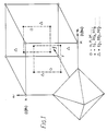
- Figures 1 and 2 illustrate the band limiting applied in a three-dimensional space having a horizontal frequency axis m in cycles per picture width (c/pw), a vertical frequency axis n in cycles per picture height (c/ph) and a time axis f related to the field frequency.
- the stationary-area filtering is defined by the octohedral shape shown in Figure 1 which has apices half-way along the m and n axes to the next repeat and only a quarter of the way along the f axis.
- the filter surface intersects the m and n axes one quarter of the way along while the f axis is intersected half-way along.
- a movement detector is used to apply the characteristic of Figure 2 in areas of movement and the characteristics of Figure 1 in stationary areas.
- the second step is to re-sample each of the pre-filtered signals at a lower rate, in a way which avoids spectral overlap in critical areas and packs the resulting repeat spectra neatly into the available space.
- a suitable sampling structure in which a 4:1 reduction is achieved by spreading the transmission over four fields rather than the normal two, is shown in Figure 3. Other structures could be used.
- Prior to re-sampling or sub-sampling samples occur on each picture at each of the points marked 0 in the top left-hand corner of Figure 3. However, in this example a 4:1 or 8:1 reduction is obtained (depending upon whether the 1249 line signal is interlaced or sequential) by only transmitting the samples marked with the numbers 1 to 4, and in particular on field 1 only transmitting the samples marked 1, etc.
- This sub-sampling operation is in fact similar to that used in "MUSE", mentioned above, for example.
- the sub-sampling is of course the same whether the filter characteristic of Figure 1 or that of Figure 2 is being used. Note that this structure is not directly suited to transmission in a 625 line channel.
- the sub-sampling causes repeats of the frequency spectra in the three-dimensional space of Figure 1 and 2.
- the filter characteristic shapes are such that when repeated the filter pass bands, i.e. the volumes defined by the shapes, do not overlap.
- the samples are re-organised for transmission by vertical re-positioning.
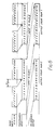
- This line standard conversion operation is illustrated in Figure 4 for the first two fields in the four field sequence. All the samples from lines 1 and 3 of the 1249 format which are transmitted on field 1 are now transmitted on line 1 of the 625 format. The following two fields are treated in exactly the same manner. In this way, twice the number of samples can be packaged into half the number of transmitted lines, to form a 625 line based system.
- an HDTV receiver equipped with a picture store can re-position the samples before interpolation, to produce a high definition image as before.
- the HDTV receiver can undo the positioning operation of Figure 4 to redistribute the field 1 samples back between lines 1 and 3 of the 1249 line format.
- Figure 5 shows in block schematic form a circuit for vertical re-positioning of the samples as illustrated in Figure 4.
- the circuit of Figure 5 uses two RAM stores 4,5 and a simple address generator.
- a counter 7 generates a basic address sequence of length 2M where M is the number of samples per input line. Thus counter 7 counts from zero to 2M-1. This basic sequence is used to address whichever RAM is currently being written into. Address routing is achieved by switches 8 and 9. A modified address sequence is required to read samples from the RAMs with the appropriate re-ordering. This sequence is generated by an adder 10 and a switch 11. The monotonic address sequence from counter 7 is divided by two by bit shifting to give a count which increments for every second sample. The least significant bit is now used to control switch 11 which feeds a zero to adder 10 when the bit is a logic low and the number M when it is a logic high. Thus all even addresses are halved, and all odd addresses are halved and increased by M.
- Figure 6 shows that this is the required form of re-positioning or "shuffling" for the samples.
- Figure 6 is described in relation to a line length of only 8 selected samples, purely as a simple illustration.
- Figure 7 illustrates an alternative configuration using a single RAM store 12 and a more complex address generator 13.
- the RAM store performs a read operation immediately followed by a write to the same address, as shown in Figure 8. It follows that the address sequence must be modified for each successive output line in order for the output samples to appear appropriately shuffled. This string of address sequences does repeat however, but the repeat period is dependent upon the number of samples per output line.
- Active line lengths for CCIR recommendation 601 and the MAC transmission standard are 720 and 697 samples respectively. An output line length of 720 samples repeats after 358 lines, and a line length of 698 samples repeats after 39 lines (697 has an enormously long repeat period, probably because its two factors 17 and 41 are both prime numbers).
- the address generator will therefore be more complex than for the previous example though there are savings in RAM storage.
- circuits similar to Figure 5 or Figure 7 can be used with the delay 1 and switch 2 transferred to the output of the circuit.
- the commutation must be approximately rephased, in Figure 5 by reversing the polarity of the switches 2, 8 and 9, and in Figure 7 by using a converse address generator 13.
- a method for the transmission of a 4:1 bandwidth reduced television signal, having a resolution approaching that of a 1249 line source standard, through a 625 line based transmission channel.
- the performance of a HDTV receiver is not compromised by re-packaging the transmitted information, nor is the complexity of the receiver significantly increased.
- a recognisable picture should be produced when a conventional receiver is fed directly with the bandwidth reduced signal. There will however be a degree of moving alias while the encoder is applying the high spatial detail pre-filter of Figure 1. This aliasing will therefore be confined to stationary and well correlated moving areas. It appears that the additional aliasing caused by re-packaging the signal for transmission via a 625 line based channel, will be negligible compared to that caused by not using a suitable post-filter.
Landscapes
- Engineering & Computer Science (AREA)
- Multimedia (AREA)
- Signal Processing (AREA)
- Television Systems (AREA)
- Compression Or Coding Systems Of Tv Signals (AREA)
Abstract
Description
- This invention relates to a method of transmitting a video signal at a higher line standard over a transmission channel for signals at a lower standard, and to transmitting and receiving apparatus for use in the method.
- Various methods have been proposed for transmitting high definition images, at a reduced bandwidth, but at the same basic line rate as is used for source and display. One example of this type of system is NHK's "MUSE", which operates entirely at 1125 lines. Other techniques have been proposed for packing extra spatial detail, but usually less than is claimed for HDTV ("high-definition television"), into a standard channel such as C-MAC or D2-MAC. These two approaches are described respectively in the following papers, (1) Ninomaya, Y. et al. 1984. A single Channel HDTV Broadcast System - The Muse. NHK Laboratory Note No 304, and (2) Arragon, J-P. et. al. 1986. Transmission d'images de Televison a Haut Definition Compatible avec le Standard D2-MAC Paquet. Acta Electronica 27, 1-2. IBA Techinical review 21, Nov. 83, entitled "compatible higher-definition television" discloses a system in which a 1250/100/2:1 source is applied to a Vertical-Temporal Pre-Filter and Down-converted to a 625/50/2:1 transmission signal, and motion adaptive Up-conversion after transmission. However, this system does not consider the problem of transmitting a bandwidth reduced higher definition signal through a standard 625 or 525 line channel in such a manner that the effectiveness of the bandwidth reduction decoder in reproducing the resolution of the bandwidth reduced signal is not prejudiced.
- This invention in its various aspects is defined in the appended claims.
- The invention will now be described in more detail by way of example with reference to the accompanying drawings, in which:-
- Figure 1 is a diagram illustrating the bandlimiting provided in a bandwidth compression prefilter in three dimensional space for stationary picture areas (or well-correlated moving areas);
- Figure 2 is a diagram similar to Figure 1 for areas in which uncorrelated movement occurs;
- Figure 3 is a diagram illustrating the sampling structure for a 4:1 bandwidth reduction;
- Figure 4 is a diagram illustrating the subsequent re-ordering of the samples to produce a signal for transmission at standard e.g. 625 line rate;
- Figure 5 is a block circuit diagram of a circuit which can be used at the transmitter to re-order or "shuffle" the samples, using two RAM stores;
- Figure 6 is a diagram illustrating the sample shuffling with the circuit of Figure 5 on an illustrative line having only eight samples;
- Figure 7 is a block circuit diagram of a sample shuffler using one RAM circuit; and
- Figure 8 is a diagram similar to Figure 6 for the circuit of Figure 7.
- This specification describes a method of allowing transmission of 1249-line HDTV resolution signals via a 625 line based transmission channel.
- In implementing the method the first operation is to bandwidth reduce the signal. This operation can be done by applying pre-filters as shown in Figures 1 and 2 to stationary and moving areas respectively. Figures 1 and 2 illustrate the band limiting applied in a three-dimensional space having a horizontal frequency axis m in cycles per picture width (c/pw), a vertical frequency axis n in cycles per picture height (c/ph) and a time axis f related to the field frequency. The stationary-area filtering is defined by the octohedral shape shown in Figure 1 which has apices half-way along the m and n axes to the next repeat and only a quarter of the way along the f axis. In the moving-area filter characteristic defined by the cuboid shape in Figure 2, the filter surface intersects the m and n axes one quarter of the way along while the f axis is intersected half-way along. A movement detector is used to apply the characteristic of Figure 2 in areas of movement and the characteristics of Figure 1 in stationary areas.
- An added level of sophistication is to add motion vector measurement and compensation as described in our British Patent Application 86 17320 (WO8705769) and in a paper read by THOMAS, G.A., at the 128th SMPTE Technical Conference, 24-29 October 1986, New York, Preprint No. 128-49 to extend the spatial detail available from the pre-filter of Figure 1 to all well-correlated moving areas. The use of motion vector compensation will be highly desirable in a fully matured bandwidth reduction system since the eye's visual acuity for tracked motion, at the speeds commonly encountered in television (say a maximum of 10 degrees/sec), is little different from its value for stationary detail.
- The second step is to re-sample each of the pre-filtered signals at a lower rate, in a way which avoids spectral overlap in critical areas and packs the resulting repeat spectra neatly into the available space. A suitable sampling structure, in which a 4:1 reduction is achieved by spreading the transmission over four fields rather than the normal two, is shown in Figure 3. Other structures could be used. Prior to re-sampling or sub-sampling samples occur on each picture at each of the points marked 0 in the top left-hand corner of Figure 3. However, in this example a 4:1 or 8:1 reduction is obtained (depending upon whether the 1249 line signal is interlaced or sequential) by only transmitting the samples marked with the
numbers 1 to 4, and in particular onfield 1 only transmitting the samples marked 1, etc. This sub-sampling operation is in fact similar to that used in "MUSE", mentioned above, for example. The sub-sampling is of course the same whether the filter characteristic of Figure 1 or that of Figure 2 is being used. Note that this structure is not directly suited to transmission in a 625 line channel. - The sub-sampling causes repeats of the frequency spectra in the three-dimensional space of Figure 1 and 2. The filter characteristic shapes are such that when repeated the filter pass bands, i.e. the volumes defined by the shapes, do not overlap.
- In the third step the samples are re-organised for transmission by vertical re-positioning. This line standard conversion operation is illustrated in Figure 4 for the first two fields in the four field sequence. All the samples from
lines field 1 are now transmitted online 1 of the 625 format. The following two fields are treated in exactly the same manner. In this way, twice the number of samples can be packaged into half the number of transmitted lines, to form a 625 line based system. - Using this packaging scheme, an HDTV receiver equipped with a picture store can re-position the samples before interpolation, to produce a high definition image as before. In other words the HDTV receiver can undo the positioning operation of Figure 4 to redistribute the
field 1 samples back betweenlines - At the same time, a conventional 625 line receiver would doubtless produce a recognisable picture, without the need for a display up-converter. There would however be aliasing additional to that caused by the bandwidth reduction system alone. We believe it likely that the total aliasing would not be significantly worse than that arising from the spectral folding in stationary and well-correlated moving areas introduced by the bandwidth compression.
- Figure 5 shows in block schematic form a circuit for vertical re-positioning of the samples as illustrated in Figure 4. The circuit of Figure 5 uses two
RAM stores - In Figure 5 the appropriate samples from two consecutive input lines are concatenated by means of a
delay 1 of a length equal to the line blanking period of the incoming vision signal, as shown in Figure 6, and aselector switch 2. These newly concatenated lines are written alternately into theRAM stores distributor switch 3. When thefirst RAM 4 is being written into, thesecond RAM 5 is being read from, and vice versa. The appropriate output data is selected by aswitch 6 which operates in antiphase to switch 3. - A
counter 7 generates a basic address sequence oflength 2M where M is the number of samples per input line. Thus counter 7 counts from zero to 2M-1. This basic sequence is used to address whichever RAM is currently being written into. Address routing is achieved byswitches adder 10 and aswitch 11. The monotonic address sequence fromcounter 7 is divided by two by bit shifting to give a count which increments for every second sample. The least significant bit is now used to controlswitch 11 which feeds a zero to adder 10 when the bit is a logic low and the number M when it is a logic high. Thus all even addresses are halved, and all odd addresses are halved and increased by M. - Figure 6 shows that this is the required form of re-positioning or "shuffling" for the samples. Figure 6 is described in relation to a line length of only 8 selected samples, purely as a simple illustration.
- Figure 7 illustrates an alternative configuration using a
single RAM store 12 and a morecomplex address generator 13. The RAM store performs a read operation immediately followed by a write to the same address, as shown in Figure 8. It follows that the address sequence must be modified for each successive output line in order for the output samples to appear appropriately shuffled. This string of address sequences does repeat however, but the repeat period is dependent upon the number of samples per output line. Active line lengths for CCIR recommendation 601 and the MAC transmission standard are 720 and 697 samples respectively. An output line length of 720 samples repeats after 358 lines, and a line length of 698 samples repeats after 39 lines (697 has an enormously long repeat period, probably because its two factors 17 and 41 are both prime numbers). The address generator will therefore be more complex than for the previous example though there are savings in RAM storage. - In the decoder, circuits similar to Figure 5 or Figure 7 can be used with the
delay 1 andswitch 2 transferred to the output of the circuit. The commutation must be approximately rephased, in Figure 5 by reversing the polarity of theswitches address generator 13. - In summary, a method is proposed for the transmission of a 4:1 bandwidth reduced television signal, having a resolution approaching that of a 1249 line source standard, through a 625 line based transmission channel. The performance of a HDTV receiver is not compromised by re-packaging the transmitted information, nor is the complexity of the receiver significantly increased.
- A recognisable picture should be produced when a conventional receiver is fed directly with the bandwidth reduced signal. There will however be a degree of moving alias while the encoder is applying the high spatial detail pre-filter of Figure 1. This aliasing will therefore be confined to stationary and well correlated moving areas. It appears that the additional aliasing caused by re-packaging the signal for transmission via a 625 line based channel, will be negligible compared to that caused by not using a suitable post-filter.
- While the invention has been described in terms of a 1249 line HDTV signal and a 625 line based channel it will be appreciated that it is not limited to such numerical values. Also it may be employed in bandwidth reduction such as recording and the terms "transmission" and "transmission channel" should be construed accordingly.
Claims (13)
- A method of transmitting a video signal representing an image and originating at a relatively higher line standard over a transmission channel intended for signals at a lower line standard, in which the bandwidth of the higher line standard signal is first reduced to substantially one quarter of the bandwidth of the original higher line standard signal by the encoder of a bandwidth reduction system which pre-filters the video signal by at least two different methods and selects one signal filtered by one of the methods in accordance with a measurement of movement in areas of the image, the method comprising transmitting samples of two lines of the bandwidth reduced higher line standard signal on a single line of the lower line standard, the samples transmitted on a single line of the lower line standard all being chosen from the same field of the bandwidth reduced higher line standard signal and the samples of two lines of the bandwidth reduced higher line standard signal being so formed as not to prejudice the ability of a bandwidth reduction decoder at a receiver to resolve the transmitted signal to the full resolution available from the said bandwidth reduction system comprising the said bandwidth reduction encoder and decoder.
- A method according to claim 1 wherein samples of two lines of the bandwidth reduced higher line standard signal transmitted as a single line are obtained by prefiltering and then quincunxially resampling at a lower rate, the resampled signal being transmitted over twice the number of fields as the prefiltered signal.
- A method according to claim 2 wherein the samples of the resampled signal are vertically repositioned by moving samples transmitted on alternate lines of a given field to a single line at the lower line standard.
- Transmitting apparatus for transmitting a video signal representing an image comprising means for receiving an input video signal at a relatively higher line standard, a bandwidth reduction encoder for reducing the bandwidth of the input video signal to substantially one quarter of the bandwidth of the input signal, and which pre-filters the video signal by at least two different methods and selects one of the signals prefiltered by one of the methods in accordance with a measurement of movement in areas of the image, output means for applying an output signal to a transmission channel, conversion means (1-13) for converting the bandwidth reduced input signal to a lower line standard prior to application to a transmission channel, by transmitting samples of two lines of the higher line standard on a single line of the lower standard, the two bandwidth reduced higher line standard lines being taken from the same field, and the samples of the two bandwidth reduced higher line standard lines being so formed as not to prejudice the ability of a bandwidth reduction decoder at a receiver to resolve the transmitted signal to the full resolution available from the said bandwidth reduction system comprising the said bandwidth reduction encoder and decoder.
- Apparatus according to claim 4, in which at the lower standard, the samples of the output signal at the lower line standard are derived alternately from the two input lines at higher line standard.
- Apparatus according to claim 5, in which the two input lines are adjacent lines in one field of an interlaced signal.
- Apparatus according to claim 4, 5 or 6, in which the conversion means comprises RAM store means (4, 5) and addressing circuitry therefor (1-3).
- Apparatus according to claim 4, 5, 6 or 7 comprising re-sampling means for resampling the bandwidth reduced higher line standard signals.
- Apparatus according to any of claims 4 to 8, in which the re-sampling means includes means for transmitting samples of the re-sampled signal over twice the number of fields as the prefiltered signal, and vertical repositioning means for moving samples transmitted on alternate lines of a given field to a single line at the lower line standard.
- Receiving apparatus for receiving a video signal transmitted according to the method of claim 1, comprising input means for receiving from a transmission channel the transmitted video signal at a relatively lower line standard, output means for supplying an output signal for display or further processing and including a decoder of a bandwidth reduction system for decoding signals encoded by at least two different methods in the bandwidth reduction encoder of Claim 1, conversion means for converting the input video signal to a signal at a higher line standard and comprising means for distributing samples on a single line of the lower line standard input signal to form the samples for two output lines at a higher line standard, each line at the output standard being derived from alternate samples at the input standard and formed that the ability of the bandwidth reduction decoder to resolve the output line standard signal to the full resolution available from the bandwidth reduction system comprising the bandwidth reduction encoder and decoder is not prejudiced.
- Apparatus according to claim 10, in which the two output lines are adjacent lines in one field of an interlaced signal.
- Apparatus according to claim 10 or 11, in which the conversion means comprises RAM store means and addressing circuitry therefor.
- Apparatus according to claim 10, 11 or 12, including interpolation means coupled to receive the output of the conversion means.
Applications Claiming Priority (2)
| Application Number | Priority Date | Filing Date | Title |
|---|---|---|---|
| GB8620110 | 1986-08-19 | ||
| GB868620110A GB8620110D0 (en) | 1986-08-19 | 1986-08-19 | Video transmission system |
Publications (2)
| Publication Number | Publication Date |
|---|---|
| EP0277141A1 EP0277141A1 (en) | 1988-08-10 |
| EP0277141B1 true EP0277141B1 (en) | 1992-12-02 |
Family
ID=10602889
Family Applications (1)
| Application Number | Title | Priority Date | Filing Date |
|---|---|---|---|
| EP87900236A Expired - Lifetime EP0277141B1 (en) | 1986-08-19 | 1986-12-23 | Video transmission systems |
Country Status (6)
| Country | Link |
|---|---|
| US (1) | US4884138A (en) |
| EP (1) | EP0277141B1 (en) |
| JP (1) | JPH01500789A (en) |
| DE (1) | DE3687234T2 (en) |
| GB (1) | GB8620110D0 (en) |
| WO (1) | WO1988001462A1 (en) |
Families Citing this family (16)
| Publication number | Priority date | Publication date | Assignee | Title |
|---|---|---|---|---|
| US5053859A (en) * | 1987-09-02 | 1991-10-01 | Scientific-Atlanta, Inc. | High definition B-MAC television signal transmission system |
| GB8817979D0 (en) * | 1988-07-28 | 1988-09-01 | British Broadcasting Corp | Application of spectrum folding bandwidth reduction to pal ntsc & secam |
| FR2633135B1 (en) * | 1988-06-17 | 1990-11-09 | France Etat Armement | DECODER FOR RECEIVER OF BROADCAST HIGH DEFINITION TELEVISION PROGRAMS |
| US4989091A (en) * | 1988-11-16 | 1991-01-29 | Scientific-Atlanta, Inc. | Scan converter for a high definition television system |
| JPH0346479A (en) * | 1989-07-14 | 1991-02-27 | Toshiba Corp | Television signal converter |
| FR2651401B1 (en) * | 1989-08-25 | 1996-08-02 | Thomson Consumer Electronics | CAMERA AND VISUALIZATION DEVICE. |
| US5617218A (en) * | 1989-09-07 | 1997-04-01 | Advanced Television Test Center | Bi-directional television and motion picture film to magnetic tape format digital signal converter |
| US5280397A (en) * | 1989-09-07 | 1994-01-18 | Advanced Television Test Center, Inc. | Bi-directional HDTV format digital signal converter |
| US5504532A (en) * | 1989-09-07 | 1996-04-02 | Advanced Television Test Center, Inc. | Bi-directional television format digital signal converter with improved luminance signal-to-noise ratio |
| GB2240230B (en) * | 1990-01-18 | 1994-04-13 | British Broadcasting Corp | Field-rate upconversion of television signals |
| US5111295A (en) * | 1990-04-20 | 1992-05-05 | Chao Lee M | Method and system for high definition color TV compatible with existing TV sets, existing broadcasting channels and existing VCR equipment |
| GB9027840D0 (en) * | 1990-12-21 | 1991-02-13 | D2B Systems Co Ltd | Video signal processing system and apparatus for use in such a system |
| US5200749A (en) * | 1991-05-28 | 1993-04-06 | Tektronix, Inc. | Format converter architecture |
| JPH05130593A (en) * | 1991-11-05 | 1993-05-25 | Matsushita Electric Ind Co Ltd | Encoding device |
| DE19619598A1 (en) * | 1996-05-15 | 1997-11-20 | Deutsche Telekom Ag | Methods for storing or transmitting stereoscopic video signals |
| CA2380105A1 (en) * | 2002-04-09 | 2003-10-09 | Nicholas Routhier | Process and system for encoding and playback of stereoscopic video sequences |
Family Cites Families (9)
| Publication number | Priority date | Publication date | Assignee | Title |
|---|---|---|---|---|
| NL164647B (en) * | 1950-10-14 | Lucas Industries Ltd | FRICTION GEAR WITH A VARIABLE TRANSMISSION RATIO WITH AUTOMATICALLY KEEPS OUTPUT SPEED. | |
| US2921124A (en) * | 1956-12-10 | 1960-01-12 | Bell Telephone Labor Inc | Method and apparatus for reducing television bandwidth |
| ATE15311T1 (en) * | 1980-01-22 | 1985-09-15 | Paul Pierre Delogne | METHOD AND SYSTEM FOR TRANSMISSION OF TELEVISION SIGNALS BY MEANS OF DIGITAL CODING OF THESE SIGNALS. |
| FR2485846A1 (en) * | 1980-06-27 | 1981-12-31 | Thomson Csf | HIGH DEFINITION TELEVISION SYSTEM |
| DE3103906A1 (en) * | 1981-02-05 | 1982-09-09 | Licentia Patent-Verwaltungs-Gmbh, 6000 Frankfurt | METHOD FOR TRANSMITTING TELEVISION SIGNALS OVER A STANDARDIZED BANDWIDTH-LIMITED TRANSMISSION CHANNEL AND ARRANGEMENT FOR CARRYING OUT THE METHOD |
| JPS5923842B2 (en) * | 1981-09-28 | 1984-06-05 | 株式会社島津製作所 | electrodialysis machine |
| GB2115641B (en) * | 1982-02-24 | 1986-08-06 | Rca Corp | Compatible high definition television system |
| DE3472744D1 (en) * | 1983-01-25 | 1988-08-18 | Bosch Gmbh Robert | High resolution colour video signal transmission system |
| US4605950A (en) * | 1983-09-20 | 1986-08-12 | Cbs Inc. | Two channel compatible high definition television broadcast system |
-
1986
- 1986-08-19 GB GB868620110A patent/GB8620110D0/en active Pending
- 1986-12-23 WO PCT/GB1986/000797 patent/WO1988001462A1/en not_active Ceased
- 1986-12-23 DE DE8787900236T patent/DE3687234T2/en not_active Expired - Fee Related
- 1986-12-23 US US07/174,792 patent/US4884138A/en not_active Expired - Fee Related
- 1986-12-23 EP EP87900236A patent/EP0277141B1/en not_active Expired - Lifetime
- 1986-12-23 JP JP62500322A patent/JPH01500789A/en active Pending
Non-Patent Citations (2)
| Title |
|---|
| IBA Technical Review 21, Nov. 83 "Compatible Higher-Definition Television." * |
| S.M.P.T.E. Journal, vol. 92, no. 10, October 1983 (Scarsdale, New York, US), Broden Wendland, "Extended Definition Television with High Picture Quality", pages 1028-1035, left-hand column, line 18; figure 15 * |
Also Published As
| Publication number | Publication date |
|---|---|
| WO1988001462A1 (en) | 1988-02-25 |
| EP0277141A1 (en) | 1988-08-10 |
| DE3687234D1 (en) | 1993-01-14 |
| US4884138A (en) | 1989-11-28 |
| GB8620110D0 (en) | 1986-10-01 |
| DE3687234T2 (en) | 1993-05-27 |
| JPH01500789A (en) | 1989-03-16 |
Similar Documents
| Publication | Publication Date | Title |
|---|---|---|
| US4884138A (en) | Video transmission systems | |
| US5182645A (en) | Apparatus for deriving a compatible low-definition interlaced television signal and other components for reconstructing the original signal from an interlaced high-definition television signal | |
| US5231491A (en) | Television system providing wide aspect ratio image information compatible with a standard aspect ratio format | |
| US4567508A (en) | Two-channel compatible television transmission system for wide picture formats | |
| US4908697A (en) | Two-line mac high definition television system | |
| CA1230669A (en) | Progressive scan television display system | |
| EP0569976A2 (en) | Video signal converting apparatus with reduced processing for aliasing interference | |
| GB2194409A (en) | Compatible high definition video transmission systems | |
| JPWO1993000771A1 (en) | Sub-sampled transmission method for improving picture quality in the moving image region of wideband color video signals | |
| US4907069A (en) | Two-channel compatible HDTV system | |
| EP0352964A2 (en) | Improvements in television signals | |
| US5113242A (en) | Two-line MAC high definition television system | |
| US5053859A (en) | High definition B-MAC television signal transmission system | |
| JPS63256079A (en) | High quality television picture transmission system and its transmitter and receiver | |
| EP0259004A1 (en) | Television transmission apparatus | |
| US5055915A (en) | Method and apparatus for the transmission and reception of two conventional television signals using a two-line MAC format | |
| US4698665A (en) | Color television transmission or information storage system, respectively with time-division multiplex coding and data generator and receiver suitable therefor | |
| JP2763346B2 (en) | Scan line conversion vertical filter for down conversion of the number of scan lines | |
| JPH0428196B2 (en) | ||
| JP2594596B2 (en) | Image signal transmission method | |
| JP2619076B2 (en) | Television system converter | |
| JP3603393B2 (en) | Television circuit | |
| JPS61261982A (en) | High definition television receiver | |
| JPH07500711A (en) | Improvements in television systems | |
| JPH02302188A (en) | Standard/high definition television receiver |
Legal Events
| Date | Code | Title | Description |
|---|---|---|---|
| PUAI | Public reference made under article 153(3) epc to a published international application that has entered the european phase |
Free format text: ORIGINAL CODE: 0009012 |
|
| AK | Designated contracting states |
Kind code of ref document: A1 Designated state(s): DE FR NL |
|
| 17P | Request for examination filed |
Effective date: 19880316 |
|
| 17Q | First examination report despatched |
Effective date: 19900705 |
|
| GRAA | (expected) grant |
Free format text: ORIGINAL CODE: 0009210 |
|
| AK | Designated contracting states |
Kind code of ref document: B1 Designated state(s): DE FR NL |
|
| REF | Corresponds to: |
Ref document number: 3687234 Country of ref document: DE Date of ref document: 19930114 |
|
| ET | Fr: translation filed | ||
| PLBE | No opposition filed within time limit |
Free format text: ORIGINAL CODE: 0009261 |
|
| STAA | Information on the status of an ep patent application or granted ep patent |
Free format text: STATUS: NO OPPOSITION FILED WITHIN TIME LIMIT |
|
| 26N | No opposition filed | ||
| PGFP | Annual fee paid to national office [announced via postgrant information from national office to epo] |
Ref country code: NL Payment date: 19931231 Year of fee payment: 8 |
|
| PGFP | Annual fee paid to national office [announced via postgrant information from national office to epo] |
Ref country code: DE Payment date: 19940225 Year of fee payment: 8 |
|
| PGFP | Annual fee paid to national office [announced via postgrant information from national office to epo] |
Ref country code: FR Payment date: 19940928 Year of fee payment: 9 |
|
| PG25 | Lapsed in a contracting state [announced via postgrant information from national office to epo] |
Ref country code: NL Effective date: 19950701 |
|
| PG25 | Lapsed in a contracting state [announced via postgrant information from national office to epo] |
Ref country code: FR Effective date: 19950831 |
|
| NLV4 | Nl: lapsed or anulled due to non-payment of the annual fee |
Effective date: 19950701 |
|
| PG25 | Lapsed in a contracting state [announced via postgrant information from national office to epo] |
Ref country code: DE Effective date: 19950901 |
|
| REG | Reference to a national code |
Ref country code: FR Ref legal event code: ST |