EP0276582A1 - R-switch with transformers - Google Patents
R-switch with transformers Download PDFInfo
- Publication number
- EP0276582A1 EP0276582A1 EP87311547A EP87311547A EP0276582A1 EP 0276582 A1 EP0276582 A1 EP 0276582A1 EP 87311547 A EP87311547 A EP 87311547A EP 87311547 A EP87311547 A EP 87311547A EP 0276582 A1 EP0276582 A1 EP 0276582A1
- Authority
- EP
- European Patent Office
- Prior art keywords
- waveguide
- switch
- paths
- transformer
- ports
- Prior art date
- Legal status (The legal status is an assumption and is not a legal conclusion. Google has not performed a legal analysis and makes no representation as to the accuracy of the status listed.)
- Granted
Links
- 238000002955 isolation Methods 0.000 description 14
- 238000000034 method Methods 0.000 description 4
- 238000005457 optimization Methods 0.000 description 4
- 230000009467 reduction Effects 0.000 description 4
- 230000004044 response Effects 0.000 description 3
- 238000005549 size reduction Methods 0.000 description 3
- 238000004891 communication Methods 0.000 description 2
- 238000005259 measurement Methods 0.000 description 2
- 230000004075 alteration Effects 0.000 description 1
- 230000005540 biological transmission Effects 0.000 description 1
- 230000008859 change Effects 0.000 description 1
- 238000010586 diagram Methods 0.000 description 1
- 238000011038 discontinuous diafiltration by volume reduction Methods 0.000 description 1
- 230000008569 process Effects 0.000 description 1
Images



Classifications
-
- H—ELECTRICITY
- H01—ELECTRIC ELEMENTS
- H01P—WAVEGUIDES; RESONATORS, LINES, OR OTHER DEVICES OF THE WAVEGUIDE TYPE
- H01P1/00—Auxiliary devices
- H01P1/10—Auxiliary devices for switching or interrupting
- H01P1/12—Auxiliary devices for switching or interrupting by mechanical chopper
- H01P1/122—Waveguide switches
Definitions
- This invention relates to a microwave waveguide switch and, in particular, to an R-switch that has a transformer located in at least one of the waveguide paths.
- R-switches It is known to use R-switches in communication satellites. In fact, in most satellites, numerous R-switches are employed.
- the size of the R-switch is important as there are so many of them used in a spacecraft and weight and volume reductions can result in large cost savings. Also, the size of the R-switch can impose restraints on a transponder layout and a reduction in size and volume of R-switches can provide extra flexibility in the layout process.
- an R-switch has three waveguide paths, a straight central path and two curved E-bend waveguide paths.
- the two outer paths have waveguide corners instead of curved E-bends.
- the waveguide corner R-switch has worse isolation and return loss performance compared to the E-bend R-switch.
- the straight waveguide in the centre path limits the amount of size reduction that can be achieved.
- R-switches are generally used in association with an actuator which moves the R-switch to various predetermined positions. Since there are numerous R-switches used in most communication satellites, any mass or volume saving can result in a substantial overall saving.
- a waveguide R-switch in accordance with the present invention for use with an actuator has a rotor rotatably mounted within a housing.
- the rotor has at least three waveguide paths and the housing has ports suitably located therein to correspond with one or more of said paths when said R-switch is in a particular position.
- a transformer is located within at least one of said paths. The actuator rotates the rotor within said housing to a plurality of predetermined positions.
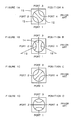
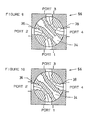
- FIGS 1A, 1B, 1C and 1D there is shown four predetermined positions of a typical R-switch 10.
- an R-switch is a three position switch and can be operated in the positions shown in Figures 1A, 1B and 1C.
- a four position switch which includes the additional position shown in Figure 1D can also be utilized.
- a rotor 12 is located within a housing 13 and the waveguide paths are shown with lines extending beyond the rotor representing ports 1, 2, 3, 4 of the housing 13.
- the R-switch 10 of Figure 1 has three waveguide paths, a central path 14 and two outer paths 16, 18.
- the R-switch 10 is in a first position A with waveguide path 16 connecting ports 1 and 2 and waveguide path 18 connecting ports 3 and 4.
- the central path 14 is closed off.
- the R-switch 10 is shown in a second position B with the waveguide path 14 connecting ports 1, 3 and the remaining paths 16, 18 being closed off.
- the R-switch 10 is shown in a third position C with waveguide path 16 interconnecting ports 2 and 3 and waveguide path 18 interconnecting ports 1 and 4.
- the remaining path 14 is closed off.
- an R-switch 10 in a fourth position D with waveguide path 14 interconnecting ports 2 and 4. The remaining paths 16, 18 are closed off.
- the first three positions are commonly used in prior art R-switches.
- a four position R-switch having all four of the positions discussed above can be utilized.
- the R-switch of the present invention can be utilized as a three position R-switch or a four position R-switch.
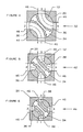
- FIG 2 there is shown a sectional top view of a prior art R-switch 10 having a rotor 12 rotatably mounted within a housing 20.
- the R-switch has a central waveguide path 14 and two outer waveguide paths 16, 18.
- the outer waveguide paths have what is referred to as an E-bend. While the R-switch 10 of Figure 2 is shown in a first position, the R-switch could be activated to any predetermined position.
- FIG 3 there is shown what is referred to in the prior art as a waveguide corner R-switch 22.
- the R-switch 22 is not as commonly used as the R-switch 10. It too has a rotor 12 mounted in a housing 20 with a central waveguide path 14 and two outer waveguide paths 24, 26.
- the outer waveguide paths 24, 26 are referred to as waveguide corner paths and are different from the E-bend paths 16, 18 shown in Figure 2.
- the main difference is that the paths 24, 26 are not a smooth curve but have corners 28 and are open to an interior surface 30 of the housing 20. It can readily be seen that the rotor 12 shown in Figure 3 can be lighter and slightly smaller than the rotor 12 shown in Figure 2.
- the R-switch 22 results in a greatly reduced isolation and worse return loss performance compared to the R-switch 10 of Figure 2.
- the straight waveguide in the central path 14 limits the amount of size reduction that can be achieved.
- the R-switch 10 provides full waveguide band operation while the R-switch 22 is operable over only a small fraction of the waveguide bandwidth. Operation of an R-switch over the full waveguide band is not required in most satellite applications. Usually, a small fraction of the waveguide bandwidth is sufficient. However, the larger the fraction, the greater the flexibility of use of the R-switch.
- FIG 4 there is shown an R-switch 32 with a rotor 12 rotatably mounted within a housing 20.
- the rotor has at least three waveguide paths, a central path 34 and two outer paths 36, 38.
- the outer paths 36, 38 are E-bend paths.
- the housing 20 has ports 1, 2, 3, 4 suitably located therein to correspond with one or more of said paths 34, 36, 38 when said R-switch is in a particular position.
- the central path 34 has a three-step transformer located within it.
- the outer paths 36, 38 are E-bend paths.
- One of the ports 1, 2, 3, 4 is located in each of the four side walls 40 of the housing 20.
- the R-switch 32 is drawn approximately to scale relative to the R-switch 10 shown in Figure 2 and it can readily be seen that the R-switch 32 is significantly smaller in size than the prior art R-switch 10.
- Each of the paths 34, 36, 38 has a 'b' dimension, being the width of the waveguide path and an 'a' dimension being the height or depth of the waveguide path.
- the dimension 'b' of the waveguide path 34 is reduced in steps. Throughout the specification, this step reduction in the 'b' dimension is referred to as a transformer. Each waveguide section between two steps is referred to as a transformer section.
- a transformer section Each waveguide section between two steps is referred to as a transformer section.
- the waveguide path 34 is said to contain a three-section transformer because three waveguide sections, with a reduced 'b' dimension, are inserted between the interface waveguides at either end of the path 34.
- the VSWR bandwidth in the path 34 after the dimensional alteration is less than the complete waveguide bandwidth.
- the transformer in the bandwidth can be designed so that it provides a good VSWR match for the particular operating frequency band of a satellite.
- an R-switch 42 has three waveguide paths 34, 36, 38 where all three paths contain a transformer.
- the R-switch 42 has a three-section transformer in each of the waveguide paths 34, 36, 38. It can be seen that the 'b' dimension of the outer paths 36, 38, has been reduced in three sections between the interface waveguide at either end of each path.
- Figure 5 has also been drawn approximately to scale relative to Figures 4 and 2 and the approximate size reduction achieved in the R-switch 42 compared to the R-switch 32 and the prior art R-switch 10 can readily be seen.
- an R-switch 44 has one waveguide step located in each of the waveguide paths 34, 36, 38.
- ports 1, 2, 3, 4 in the housing 20 are reduced in size and are all identical in size. It can be stated that in this manner, a transformer is integrated into the housing ports and there is actually a three-section transformer located between the interface waveguides 46.
- the R-switch 44 is drawn approximately to scale and it can readily be seen that it is further reduced in size over the R-switches 42, 32 and the prior art R-switch 10.
- Figures 4, 5 and 6, only the 'b' dimension has been reduced in size and the 'a' dimension of each of the waveguide paths has remained constant. Therefore, all of the transformers are homogeneous.
- the transformer concept of the present invention is equally applicable to the non-homogeneous case.
- the transformers are not limited to a three-section design and the number of steps or sections in a transformer located within a waveguide path depends solely on the bandwidth requirements. For example, a transformer or transformers could either be 1, 2, 3, 4 or 5-section transformers.
- transformers having more than 5 sections are also feasible, from a practical point of view, these would not normally be utilized. Also, it is possible to have a transformer in the central waveguide path and not in the outer paths or to have transformers in each of the outer paths but not in the central path. Generally, the outer waveguide paths will be identical except that they will be mirror images of one another. Also, while the transformers discussed thus far have been symmetrical, it is possible to have asymmetrical transformers.
- Isolation performance is a measurement of signal leakage into the waveguide ports that are closed off when the switch is in a particular position. It is very desirable to have a high isolation performance. Isolation performance is determined by rotor configuration, number of wavelengths between adjacent waveguide paths and the availability of space for choke sections.
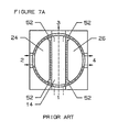
- Figures 7A, 7B and 7C there is shown a prior art R-switch 22, a prior art R-switch 10 and an R-switch 44 in accordance with the present invention respectively. All three R-switches shown are in position B as described with respect to Figure 1. In other words, ports 1 and 3 are interconnected and ports 2 and 4 are closed off.
- a leakage path can exist between the rotor and the housing at either end of the waveguide path 14 and into the waveguide paths 24, 26 and the ports 2, 4.
- a leakage path is also shown between the rotor and the housing by dotted lines.
- the leakage path of the R-switch 10 must overcome two low impedance waveguide sections 48, 50 of the rotor 12 before leaking into the ports 2, 4.
- the R-switch 22 only one low impedance section 52 of the rotor 12 must be overcome for the signal to leak from the path 14 to the ports 2, 4.
- the R-switch 10 would be expected to have a higher isolation response than the R-switch 22.
- the R-switch 44 shown in Figure 7C also has a signal leakage path to ports 2, 4 shown by dotted lines. It can readily be seen that the signal must overcome low impedance sections 48, 50 of the rotor 12 in order to leak from the path 34 to the ports 2, 4. Even though the low impedance sections 48, 50 of the rotor 12 of the R-switch 44 are smaller than the corresponding sections 48, 50 of the R-switch 10, there are two sections that must be overcome rather than one section as shown for the R-switch 22. Therefore, it would be expected that the R-switch 44 would have a higher isolation response than the R-switch 22 but a lower isolation response than the R-switch 10. The reason for this is that the phase length between the centre path 34 and the outer paths 36, 38 of the rotor 44 is smaller than that for the R-switch 10.
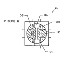
- R-switch 44 there is sufficient space between adjacent waveguide paths to locate a choke section in an R-switch 44 of the present invention.
- choke sections could also be utilized with other R-switches of the present invention, for example, R-switches 32, 42.
- Table 1 the performance, mass and size of a WR 75 waveguide R-switch used in the Ku band in accordance with the prior art E-bend R-switch 10, prior art waveguide corner R-switch 22 and an R-switch 44 in accordance with the present invention. Choke sections were utilized in the following R-switches:
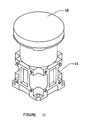
- FIG 11 there is shown a perspective view of an R-switch in accordance with the present invention with an actuator 58 located thereon.
- the actuator 58 provides means for rotating the rotor to positions A, B, C as shown in Figure 1.
- the R-switch can be a four position R-switch and can also include position D. Since the actuator mass constitutes approximately 30% to 40% of the total switch mass, it is as important to reduce the actuator mass as it is to reduce the rotor and housing mass of the R-switch. Fortunately, any reduction in the mass of the rotor automatically leads to a reduction in the actuator mass as the size and mass of the actuator is determined by the drive torque required to rotate the rotor. The fact that the actuator can be reduced in size increases the mass and volume savings for the use of an R-switch in accordance with the present invention.
- FIG 12 there is shown a transformer model that is used to provide a good correlation between physical dimensions of the transformers and the electrical performance required. Any change in waveguide dimensions are represented by corresponding changes in transmission line admittances.
- the junction susceptances B1, B2, B3, ... B n are always taken into account during the design stage. The values of these junction susceptances can be found in many publications.
- the junction model that is utilized in this design can be found in Marcuvitz's Waveguide Handbook, published by McGraw-Hill Book Company Inc., 1951, by N. Marcuvitz.
- the reflection coefficient can be computed from the following equation: where Y s is the source admittance Y is the complex conjugate of Y Y in is the input admittance of the transformer.
- Stage 1 optimizes the curve transformer dimensions subject to the rotor dimensional constraints.
- Stage 2 optimizes the straight transformer dimensions subject to both the rotor and curve transformer dimensional constraints.
- nc total number of sections in the curved transformer
- ns total number of sections in the straight transformer
- m number of frequency points
- ac i 'a' dimension of waveguide section 'i' in the curved transformer
- bc i 'b' dimension of waveguide section 'i' in the curved transformer
- lc i length of waveguide section 'i' in the curved transformer
- ac i max max 'a' dimension of waveguide section 'i' in the curved transformer
- bc i max max 'b' dimension of waveguide section 'i' in the curved transformer
- lc i max max length of waveguide section 'i' in the curved transformer
- as i : 'a' dimension of waveguide section 'i' in the straight transformer
- bs i 'b' dimension of waveguide section 'i' in the straight transformer
- ls i length of waveguide section '
Landscapes
- Waveguide Switches, Polarizers, And Phase Shifters (AREA)
Abstract
Description
- This invention relates to a microwave waveguide switch and, in particular, to an R-switch that has a transformer located in at least one of the waveguide paths.
- It is known to use R-switches in communication satellites. In fact, in most satellites, numerous R-switches are employed. The size of the R-switch is important as there are so many of them used in a spacecraft and weight and volume reductions can result in large cost savings. Also, the size of the R-switch can impose restraints on a transponder layout and a reduction in size and volume of R-switches can provide extra flexibility in the layout process.
- Usually, an R-switch has three waveguide paths, a straight central path and two curved E-bend waveguide paths. In a variation of existing R-switches, the two outer paths have waveguide corners instead of curved E-bends. Generally, the waveguide corner R-switch has worse isolation and return loss performance compared to the E-bend R-switch. Also, the straight waveguide in the centre path limits the amount of size reduction that can be achieved. R-switches are generally used in association with an actuator which moves the R-switch to various predetermined positions. Since there are numerous R-switches used in most communication satellites, any mass or volume saving can result in a substantial overall saving.
- It is an object of the present invention to provide an R-switch for use with an actuator that can be much smaller in mass and volume than existing R-switches and still have sufficient usable bandwidth, isolation and similar return loss when compared to existing R-switches.
- A waveguide R-switch in accordance with the present invention for use with an actuator has a rotor rotatably mounted within a housing. The rotor has at least three waveguide paths and the housing has ports suitably located therein to correspond with one or more of said paths when said R-switch is in a particular position. A transformer is located within at least one of said paths. The actuator rotates the rotor within said housing to a plurality of predetermined positions.
- The present invention will be better understood by an examination of the following description, together with the accompanying drawings, in which:
- Figure 1A is a schematic drawing of a prior art R-switch in position A;
- Figure 1B is a schematic drawing of a prior art R-switch in position B;
- Figure 1C is a schematic drawing of a prior art R-switch in position C;
- Figure 1D is a schematic drawing of a prior art R-switch in position D;
- Figure 2 is a sectional top view of a standard prior art R-switch having two E-bend waveguide paths;
- Figure 3 is a sectional top view of a prior art R-switch having waveguide corners;
- Figure 4 is a sectional top view of an R-switch in accordance with the present invention having a transformer in a central waveguide path;
- Figure 5 is a sectional top view of an R-switch in accordance with the present invention having transformers in all three paths;
- Figure 6 is a sectional top view of an R-switch in accordance with the present invention where the transformers are located in ports of a housing;
- Figure 7A is a sectional top view of a potential leakage path of a prior art R-switch having waveguide corners;
- Figure 7B is a sectional top view showing potential leakage paths of a prior art waveguide R-switch having E-bend paths;
- Figure 7C is a sectional top view of potential leakage paths for an R-switch in accordance with the present invention;
- Figure 8 is a sectional top view of a rotor with choke sections;
- Figure 9 is a sectional top view of an R-switch having a four-step transformer;
- Figure 10 is a sectional top view of an R-switch having a five-step transformer;
- Figure 11 is a perspective view of an R-switch and an actuator;
- Figure 12 is a circuit diagram of a transformer model; and
- Figure 13 is a schematic view of certain dimensions for an R-switch of the present invention.
- Referring to the figures in greater detail, in Figures 1A, 1B, 1C and 1D, there is shown four predetermined positions of a typical R-
switch 10. Most often, an R-switch is a three position switch and can be operated in the positions shown in Figures 1A, 1B and 1C. However, a four position switch which includes the additional position shown in Figure 1D can also be utilized. As the drawings shown in Figures 1A, 1B, 1C and 1D are schematic views only, arotor 12 is located within ahousing 13 and the waveguide paths are shown with lines extending beyond therotor representing ports housing 13. The R-switch 10 of Figure 1 has three waveguide paths, acentral path 14 and twoouter paths - In Figure 1A, the R-
switch 10 is in a first position A withwaveguide path 16 connectingports waveguide path 18 connectingports central path 14 is closed off. In Figure 1B, the R-switch 10 is shown in a second position B with thewaveguide path 14 connectingports remaining paths switch 10 is shown in a third position C withwaveguide path 16interconnecting ports waveguide path 18interconnecting ports remaining path 14 is closed off. In Figure 1D, there is shown an R-switch 10 in a fourth position D withwaveguide path 14interconnecting ports remaining paths - In Figure 2, there is shown a sectional top view of a prior art R-
switch 10 having arotor 12 rotatably mounted within ahousing 20. The R-switch has acentral waveguide path 14 and twoouter waveguide paths switch 10 of Figure 2 is shown in a first position, the R-switch could be activated to any predetermined position. - In Figure 3 there is shown what is referred to in the prior art as a waveguide corner R-
switch 22. The R-switch 22 is not as commonly used as the R-switch 10. It too has arotor 12 mounted in ahousing 20 with acentral waveguide path 14 and twoouter waveguide paths outer waveguide paths E-bend paths paths corners 28 and are open to aninterior surface 30 of thehousing 20. It can readily be seen that therotor 12 shown in Figure 3 can be lighter and slightly smaller than therotor 12 shown in Figure 2. However, the R-switch 22 results in a greatly reduced isolation and worse return loss performance compared to the R-switch 10 of Figure 2. With both prior art R-switches central path 14 limits the amount of size reduction that can be achieved. The R-switch 10 provides full waveguide band operation while the R-switch 22 is operable over only a small fraction of the waveguide bandwidth. Operation of an R-switch over the full waveguide band is not required in most satellite applications. Usually, a small fraction of the waveguide bandwidth is sufficient. However, the larger the fraction, the greater the flexibility of use of the R-switch. - In Figure 4, there is shown an R-
switch 32 with arotor 12 rotatably mounted within ahousing 20. The rotor has at least three waveguide paths, acentral path 34 and twoouter paths outer paths housing 20 hasports paths central path 34 has a three-step transformer located within it. Theouter paths ports side walls 40 of thehousing 20. The R-switch 32 is drawn approximately to scale relative to the R-switch 10 shown in Figure 2 and it can readily be seen that the R-switch 32 is significantly smaller in size than the prior art R-switch 10. Each of thepaths - In Figure 4, the dimension 'b' of the
waveguide path 34 is reduced in steps. Throughout the specification, this step reduction in the 'b' dimension is referred to as a transformer. Each waveguide section between two steps is referred to as a transformer section. To obtain a good Voltage Standing Wave Ratio (henceforth VSWR) match in the frequency band of operation betweenswitch interface waveguides 46, three waveguide 'steps' are introduced inpath 34 for impedance matching. Thewaveguide path 34 is said to contain a three-section transformer because three waveguide sections, with a reduced 'b' dimension, are inserted between the interface waveguides at either end of thepath 34. The VSWR bandwidth in thepath 34 after the dimensional alteration is less than the complete waveguide bandwidth. However, the transformer in the bandwidth can be designed so that it provides a good VSWR match for the particular operating frequency band of a satellite. - In Figure 5, an R-
switch 42 has threewaveguide paths switch 42 has a three-section transformer in each of thewaveguide paths outer paths switch 42 compared to the R-switch 32 and the prior art R-switch 10 can readily be seen. - In Figure 6, an R-
switch 44 has one waveguide step located in each of thewaveguide paths ports housing 20 are reduced in size and are all identical in size. It can be stated that in this manner, a transformer is integrated into the housing ports and there is actually a three-section transformer located between theinterface waveguides 46. - The R-
switch 44 is drawn approximately to scale and it can readily be seen that it is further reduced in size over the R-switches switch 10. In Figures 4, 5 and 6, only the 'b' dimension has been reduced in size and the 'a' dimension of each of the waveguide paths has remained constant. Therefore, all of the transformers are homogeneous. However, the transformer concept of the present invention is equally applicable to the non-homogeneous case. Further, the transformers are not limited to a three-section design and the number of steps or sections in a transformer located within a waveguide path depends solely on the bandwidth requirements. For example, a transformer or transformers could either be 1, 2, 3, 4 or 5-section transformers. While transformers having more than 5 sections are also feasible, from a practical point of view, these would not normally be utilized. Also, it is possible to have a transformer in the central waveguide path and not in the outer paths or to have transformers in each of the outer paths but not in the central path. Generally, the outer waveguide paths will be identical except that they will be mirror images of one another. Also, while the transformers discussed thus far have been symmetrical, it is possible to have asymmetrical transformers. - An important electrical parameter for waveguide switches is the measurement of isolation performance. Isolation performance is a measurement of signal leakage into the waveguide ports that are closed off when the switch is in a particular position. It is very desirable to have a high isolation performance. Isolation performance is determined by rotor configuration, number of wavelengths between adjacent waveguide paths and the availability of space for choke sections. In Figures 7A, 7B and 7C there is shown a prior art R-
switch 22, a prior art R-switch 10 and an R-switch 44 in accordance with the present invention respectively. All three R-switches shown are in position B as described with respect to Figure 1. In other words,ports ports - As can be seen from Figure 7A, a leakage path, as shown by dotted lines on said Figure, can exist between the rotor and the housing at either end of the
waveguide path 14 and into thewaveguide paths ports switch 10 shown in Figure 7B, a leakage path is also shown between the rotor and the housing by dotted lines. However, unlike the R-switch 22 it can be seen that the leakage path of the R-switch 10 must overcome two lowimpedance waveguide sections rotor 12 before leaking into theports switch 22, only onelow impedance section 52 of therotor 12 must be overcome for the signal to leak from thepath 14 to theports switch 10 would be expected to have a higher isolation response than the R-switch 22. - The R-
switch 44 shown in Figure 7C also has a signal leakage path toports low impedance sections rotor 12 in order to leak from thepath 34 to theports low impedance sections rotor 12 of the R-switch 44 are smaller than the correspondingsections switch 10, there are two sections that must be overcome rather than one section as shown for the R-switch 22. Therefore, it would be expected that the R-switch 44 would have a higher isolation response than the R-switch 22 but a lower isolation response than the R-switch 10. The reason for this is that the phase length between thecentre path 34 and theouter paths rotor 44 is smaller than that for the R-switch 10. - It is known that choke sections located between two waveguide paths will result in a better isolation performance for an R-switch. Choke sections are extra short circuit stubs that are machined into the space between two adjacent waveguide paths.
- As shown in Figure 8, there is sufficient space between adjacent waveguide paths to locate a choke section in an R-
switch 44 of the present invention. Of course, choke sections could also be utilized with other R-switches of the present invention, for example, R-switches switch 10, prior art waveguide corner R-switch 22 and an R-switch 44 in accordance with the present invention. Choke sections were utilized in the following R-switches:
- It can readily be seen from the Table that while the R-switch of the present invention has a much smaller bandwidth than the prior art R-
switch 10, it is much greater than the bandwidth of the prior art R-switch 22. Similarly, it can be seen that the isolation performance of the R-switch 44 in accordance with the present invention is much greater than the isolation performance of the prior art R-switch 22, though somewhat less than the isolation performance of the prior art R-switch 10. However, the rotor diameter and size or volume of the R-switch in accordance with the present invention is much smaller than either of the prior art R-switches. Further, the mass of the R-switch 44 is greatly reduced from that of either of the prior art R-switches. In Figure 9, there is an R-switch 56 with a four-step transformer. This transformer is asymmetrical. In Figure 10, there is shown an R-switch 56 with a five-step transformer. - In Figure 11, there is shown a perspective view of an R-switch in accordance with the present invention with an
actuator 58 located thereon. Theactuator 58 provides means for rotating the rotor to positions A, B, C as shown in Figure 1. If the actuator is suitably designed, the R-switch can be a four position R-switch and can also include position D. Since the actuator mass constitutes approximately 30% to 40% of the total switch mass, it is as important to reduce the actuator mass as it is to reduce the rotor and housing mass of the R-switch. Fortunately, any reduction in the mass of the rotor automatically leads to a reduction in the actuator mass as the size and mass of the actuator is determined by the drive torque required to rotate the rotor. The fact that the actuator can be reduced in size increases the mass and volume savings for the use of an R-switch in accordance with the present invention. - In Figure 12, there is shown a transformer model that is used to provide a good correlation between physical dimensions of the transformers and the electrical performance required. Any change in waveguide dimensions are represented by corresponding changes in transmission line admittances. The junction susceptances B₁, B₂, B₃, ... Bn are always taken into account during the design stage. The values of these junction susceptances can be found in many publications. The junction model that is utilized in this design can be found in Marcuvitz's Waveguide Handbook, published by McGraw-Hill Book Company Inc., 1951, by N. Marcuvitz.
- The reflection coefficient can be computed from the following equation:

Yis the complex conjugate of Y
Yin is the input admittance of the transformer. - It is found that this model gives a very accurate prediction of the RF performance. There may be other junction models that could be used to design the transformers in accordance with the present invention. The design procedure set out herein is only one method of designing the transformers and is not intended to limit the invention in any way.
- Having established the transformer model, it is then necessary to determine the optimum dimensions for a given frequency band under the dimensional constraints of the rotor. This is performed by numerical optimization techniques.
- A two-stage optimization algorithm is required to determine the transformer dimensions.
Stage 1 optimizes the curve transformer dimensions subject to the rotor dimensional constraints.Stage 2 optimizes the straight transformer dimensions subject to both the rotor and curve transformer dimensional constraints. - The parameters are defined as follows:
nc: total number of sections in the curved transformer;
ns: total number of sections in the straight transformer;
m: number of frequency points;
aci : 'a' dimension of waveguide section 'i' in the curved transformer;
bci : 'b' dimension of waveguide section 'i' in the curved transformer;
lci : length of waveguide section 'i' in the curved transformer;
aci max: max 'a' dimension of waveguide section 'i' in the curved transformer;
bci max: max 'b' dimension of waveguide section 'i' in the curved transformer;
lci max: max length of waveguide section 'i' in the curved transformer;
asi : 'a' dimension of waveguide section 'i' in the straight transformer;
bsi : 'b' dimension of waveguide section 'i' in the straight transformer;
lsi : length of waveguide section 'i' in the straight transformer;
asi max: max 'a' dimension of waveguide section 'i' in the straight transformer;
bsi max: max 'b' dimension of waveguide section 'i' in the straight transformer;
lsi max: max length of waveguide section 'i' in the straight transformer;
p : reflection coefficient at frequency point j;
Lmean : mean path length of curved transformer in rotor;
Lh : housing dimension (refer to Figure 14);
D : rotor diameter. - Min [ max pk (aci, bci, lci)]
i = 1,2,...nc
k = 1,2,...m
subject to:
lc₁ + lc₂ + ... + lcnc = Lmean + 2*Lh
bci < bci max
aci < aci max
Solution:
aci
bci
lci
i = 1,2,...nc
- Min [ max pj (asi, bsi, lsi)]
i = 1,2,...ns
j = 1,2,...m
subject to:
ls₁ + ls₂ + ... + lsns = D + 2*Lh
bs₁ = bc₁
bsns = bcnc
as₁ = ac₁
asns = acnc
asi < asi max
bsi < bsi max
Solution:
asi
bsi
lsi
i = 1,2,...ns
- Other methods of designing the transformers will be readily apparent to those skilled in the art.
Claims (17)
Applications Claiming Priority (2)
| Application Number | Priority Date | Filing Date | Title |
|---|---|---|---|
| CA000527164A CA1231760A (en) | 1987-01-12 | 1987-01-12 | R-switch with transformers |
| CA527164 | 1987-01-12 |
Publications (3)
| Publication Number | Publication Date |
|---|---|
| EP0276582A1 true EP0276582A1 (en) | 1988-08-03 |
| EP0276582B1 EP0276582B1 (en) | 1994-03-09 |
| EP0276582B2 EP0276582B2 (en) | 2003-06-25 |
Family
ID=4134735
Family Applications (1)
| Application Number | Title | Priority Date | Filing Date |
|---|---|---|---|
| EP87311547A Expired - Lifetime EP0276582B2 (en) | 1987-01-12 | 1987-12-31 | R-switch with transformers |
Country Status (4)
| Country | Link |
|---|---|
| US (1) | US4806887A (en) |
| EP (1) | EP0276582B2 (en) |
| CA (1) | CA1231760A (en) |
| DE (1) | DE3789297T3 (en) |
Cited By (4)
| Publication number | Priority date | Publication date | Assignee | Title |
|---|---|---|---|---|
| DE4341052A1 (en) * | 1993-12-02 | 1995-06-08 | Teldix Gmbh | Waveguide coupling for different dia. hollow waveguides |
| WO2004008567A3 (en) * | 2002-07-11 | 2004-03-04 | Tesat Spacecom Gmbh & Co Kg | R switch |
| EP1079545A3 (en) * | 1999-08-23 | 2004-09-01 | Hughes Electronics Corporation | Method for rerouting signals in a switch network |
| CN105609900A (en) * | 2015-12-23 | 2016-05-25 | 中国航天时代电子公司 | Miniature multi-channel waveguide switch |
Families Citing this family (11)
| Publication number | Priority date | Publication date | Assignee | Title |
|---|---|---|---|---|
| US4967170A (en) * | 1986-02-08 | 1990-10-30 | Teldix Gmbh | Rotary waveguide switch having arcuate waveguides realized by planar faces |
| DE4034684C1 (en) * | 1990-10-31 | 1992-06-17 | Georg Dr.-Ing. 8152 Feldkirchen-Westerham De Spinner | |
| US5583469A (en) * | 1994-12-15 | 1996-12-10 | Unisys Corporation | Dual frequency waveguide switch |
| DE19822072C1 (en) | 1998-05-16 | 2000-01-13 | Bosch Gmbh Robert | Microwave switch, e.g. for satellite application as redundant switch, achieves higher operating frequency with a significantly greater gap between the rotor and generator housing |
| US6380822B1 (en) * | 2000-02-08 | 2002-04-30 | Hughes Electronics Corporation | Waveguide switch for routing M-inputs to M of N-outputs |
| US6448869B1 (en) * | 2001-03-21 | 2002-09-10 | The Boeing Company | E-plane offset transitions in a switchable waveguide |
| US7330087B2 (en) * | 2004-02-27 | 2008-02-12 | Com Dev Ltd. | Microwave switch housing assembly |
| US9059495B2 (en) * | 2012-06-05 | 2015-06-16 | Jorge A. Ruiz-Cruz | Compact multiport waveguide switches |
| EP3332444A1 (en) * | 2015-08-03 | 2018-06-13 | European Space Agency | Microwave branching switch |
| US12271213B2 (en) * | 2022-05-03 | 2025-04-08 | Electra Aero, Inc. | Systems and methods for controlling fluid flow |
| CN115101903B (en) * | 2022-06-28 | 2023-10-20 | 中国电子科技集团公司第二十九研究所 | Spliced double-ridge waveguide switch rotor and manufacturing method thereof |
Citations (2)
| Publication number | Priority date | Publication date | Assignee | Title |
|---|---|---|---|---|
| GB2185152A (en) * | 1985-10-31 | 1987-07-08 | Gen Electric Co Plc | Waveguide switching apparatus |
| WO1987004864A1 (en) * | 1986-02-08 | 1987-08-13 | Teldix Gmbh | Waveguide switch |
Family Cites Families (8)
| Publication number | Priority date | Publication date | Assignee | Title |
|---|---|---|---|---|
| GB732443A (en) * | 1952-03-20 | 1955-06-22 | Emi Ltd | Improvements in or relating to electro-magnetic waveguides |
| US2814782A (en) * | 1954-08-06 | 1957-11-26 | Gen Precision Lab Inc | Waveguide switch |
| GB902128A (en) * | 1959-08-19 | 1962-07-25 | Decca Ltd | Improvements in or relating to waveguide couplings |
| US3072870A (en) * | 1960-07-21 | 1963-01-08 | Microwave Ass | Rectangular waveguide bend |
| US3243733A (en) * | 1964-06-03 | 1966-03-29 | Donald A Hosman | Multiway waveguide switch |
| US4201963A (en) * | 1978-01-26 | 1980-05-06 | Communications Satellite Corporation | 3-Position, 4-port waveguide switch |
| US4242652A (en) * | 1978-07-10 | 1980-12-30 | Hughes Aircraft Company | Four port waveguide switch |
| US4283685A (en) * | 1979-12-13 | 1981-08-11 | Raytheon Company | Waveguide-to-cylindrical array transition |
-
1987
- 1987-01-12 CA CA000527164A patent/CA1231760A/en not_active Expired
- 1987-05-27 US US07/054,524 patent/US4806887A/en not_active Expired - Lifetime
- 1987-12-31 EP EP87311547A patent/EP0276582B2/en not_active Expired - Lifetime
- 1987-12-31 DE DE3789297T patent/DE3789297T3/en not_active Expired - Fee Related
Patent Citations (2)
| Publication number | Priority date | Publication date | Assignee | Title |
|---|---|---|---|---|
| GB2185152A (en) * | 1985-10-31 | 1987-07-08 | Gen Electric Co Plc | Waveguide switching apparatus |
| WO1987004864A1 (en) * | 1986-02-08 | 1987-08-13 | Teldix Gmbh | Waveguide switch |
Non-Patent Citations (1)
| Title |
|---|
| C.G. MONTGOMERY et al.: "Principles of microwave circuits", edition 1, 1948, pages 188-193, McGraw-Hill Book Co., Inc., New York, US * |
Cited By (5)
| Publication number | Priority date | Publication date | Assignee | Title |
|---|---|---|---|---|
| DE4341052A1 (en) * | 1993-12-02 | 1995-06-08 | Teldix Gmbh | Waveguide coupling for different dia. hollow waveguides |
| EP1079545A3 (en) * | 1999-08-23 | 2004-09-01 | Hughes Electronics Corporation | Method for rerouting signals in a switch network |
| WO2004008567A3 (en) * | 2002-07-11 | 2004-03-04 | Tesat Spacecom Gmbh & Co Kg | R switch |
| CN105609900A (en) * | 2015-12-23 | 2016-05-25 | 中国航天时代电子公司 | Miniature multi-channel waveguide switch |
| CN105609900B (en) * | 2015-12-23 | 2018-03-27 | 中国航天时代电子公司 | A kind of miniaturized multichannel waveguide switch |
Also Published As
| Publication number | Publication date |
|---|---|
| DE3789297T2 (en) | 1994-10-06 |
| CA1231760A (en) | 1988-01-19 |
| EP0276582B2 (en) | 2003-06-25 |
| DE3789297T3 (en) | 2004-05-06 |
| DE3789297D1 (en) | 1994-04-14 |
| EP0276582B1 (en) | 1994-03-09 |
| US4806887A (en) | 1989-02-21 |
Similar Documents
| Publication | Publication Date | Title |
|---|---|---|
| EP0276582B1 (en) | R-switch with transformers | |
| US6483397B2 (en) | Tandem six port 3:1 divider combiner | |
| US5986617A (en) | Multiband antenna matching unit | |
| US4611186A (en) | Noncontacting MIC ground plane coupling using a broadband virtual short circuit gap | |
| Beyers et al. | Compact conical-line power combiner design using circuit models | |
| JPS6121601A (en) | Microwave balloon for mixer and modulator | |
| US20030011442A1 (en) | Microstrip directional coupler loaded by a pair of inductive stubs | |
| Virone et al. | A novel design tool for waveguide polarizers | |
| EP0567267A2 (en) | Signal isolating microwave splitters/combiners | |
| US4928078A (en) | Branch line coupler | |
| US7342470B2 (en) | Circuit board microwave filters | |
| Elhiwairis et al. | Miniaturized size branch line coupler using open stubs with high-low impedances | |
| US5025233A (en) | Broadband power divider | |
| Zhu et al. | Characterization of finite-ground CPW reactive series-connected elements for innovative design of uniplanar M (H) MICs | |
| US5886588A (en) | Coupling for two electromagnetic waveguides with different cross-sectional shapes | |
| Rosenberg et al. | A compact and broadband 90-degree waveguide twist transformer for integrated waveguide subsystems | |
| US4147980A (en) | Redundant rf system for space application | |
| US5347243A (en) | Non-contacting waveguide "T" switch | |
| Menzel et al. | Planar integrated waveguide diplexer for low-loss millimeter-wave applications | |
| JPH0344684B2 (en) | ||
| CA1082782A (en) | Directional coupler | |
| Wanselow | Prototype Characteristics for a Class of Dual-Mode Filters (Short Papers) | |
| Fontecha et al. | Transition rectangular to circular waveguide by means of rectangular guides | |
| LABAY et al. | Generalized modal scattering matrix of discontinuity‐distorted waveguide multiport junctions | |
| Zhang | An integrated coaxial circular-polarised OMJ/OMT for dual-band feed applications |
Legal Events
| Date | Code | Title | Description |
|---|---|---|---|
| PUAI | Public reference made under article 153(3) epc to a published international application that has entered the european phase |
Free format text: ORIGINAL CODE: 0009012 |
|
| AK | Designated contracting states |
Kind code of ref document: A1 Designated state(s): DE FR GB IT SE |
|
| 17P | Request for examination filed |
Effective date: 19890124 |
|
| 17Q | First examination report despatched |
Effective date: 19910930 |
|
| GRAA | (expected) grant |
Free format text: ORIGINAL CODE: 0009210 |
|
| AK | Designated contracting states |
Kind code of ref document: B1 Designated state(s): DE FR GB IT SE |
|
| PG25 | Lapsed in a contracting state [announced via postgrant information from national office to epo] |
Ref country code: SE Free format text: THE PATENT HAS BEEN ANNULLED BY A DECISION OF A NATIONAL AUTHORITY Effective date: 19940309 |
|
| REF | Corresponds to: |
Ref document number: 3789297 Country of ref document: DE Date of ref document: 19940414 |
|
| ITF | It: translation for a ep patent filed | ||
| ET | Fr: translation filed | ||
| PLBI | Opposition filed |
Free format text: ORIGINAL CODE: 0009260 |
|
| 26 | Opposition filed |
Opponent name: ANT NACHRICHTENTECHNIK GMBH Effective date: 19941207 |
|
| PLBQ | Unpublished change to opponent data |
Free format text: ORIGINAL CODE: EPIDOS OPPO |
|
| PLAB | Opposition data, opponent's data or that of the opponent's representative modified |
Free format text: ORIGINAL CODE: 0009299OPPO |
|
| R26 | Opposition filed (corrected) |
Opponent name: BOSCH TELECOM GMBH Effective date: 19941207 |
|
| PLAW | Interlocutory decision in opposition |
Free format text: ORIGINAL CODE: EPIDOS IDOP |
|
| REG | Reference to a national code |
Ref country code: GB Ref legal event code: IF02 |
|
| APAC | Appeal dossier modified |
Free format text: ORIGINAL CODE: EPIDOS NOAPO |
|
| APAE | Appeal reference modified |
Free format text: ORIGINAL CODE: EPIDOS REFNO |
|
| APAC | Appeal dossier modified |
Free format text: ORIGINAL CODE: EPIDOS NOAPO |
|
| APAC | Appeal dossier modified |
Free format text: ORIGINAL CODE: EPIDOS NOAPO |
|
| PLAW | Interlocutory decision in opposition |
Free format text: ORIGINAL CODE: EPIDOS IDOP |
|
| PUAH | Patent maintained in amended form |
Free format text: ORIGINAL CODE: 0009272 |
|
| STAA | Information on the status of an ep patent application or granted ep patent |
Free format text: STATUS: PATENT MAINTAINED AS AMENDED |
|
| 27A | Patent maintained in amended form |
Effective date: 20030625 |
|
| AK | Designated contracting states |
Designated state(s): DE FR GB IT SE |
|
| ET3 | Fr: translation filed ** decision concerning opposition | ||
| APAH | Appeal reference modified |
Free format text: ORIGINAL CODE: EPIDOSCREFNO |
|
| PGFP | Annual fee paid to national office [announced via postgrant information from national office to epo] |
Ref country code: FR Payment date: 20051230 Year of fee payment: 19 |
|
| PGFP | Annual fee paid to national office [announced via postgrant information from national office to epo] |
Ref country code: GB Payment date: 20060105 Year of fee payment: 19 |
|
| PGFP | Annual fee paid to national office [announced via postgrant information from national office to epo] |
Ref country code: DE Payment date: 20060124 Year of fee payment: 19 |
|
| PGFP | Annual fee paid to national office [announced via postgrant information from national office to epo] |
Ref country code: IT Payment date: 20061231 Year of fee payment: 20 |
|
| PG25 | Lapsed in a contracting state [announced via postgrant information from national office to epo] |
Ref country code: DE Free format text: LAPSE BECAUSE OF NON-PAYMENT OF DUE FEES Effective date: 20070703 |
|
| GBPC | Gb: european patent ceased through non-payment of renewal fee |
Effective date: 20061231 |
|
| REG | Reference to a national code |
Ref country code: FR Ref legal event code: ST Effective date: 20070831 |
|
| PG25 | Lapsed in a contracting state [announced via postgrant information from national office to epo] |
Ref country code: GB Free format text: LAPSE BECAUSE OF NON-PAYMENT OF DUE FEES Effective date: 20061231 |
|
| PG25 | Lapsed in a contracting state [announced via postgrant information from national office to epo] |
Ref country code: FR Free format text: LAPSE BECAUSE OF NON-PAYMENT OF DUE FEES Effective date: 20070102 |