EP0276538A2 - Partial oxidation of hydrocarbon gases - Google Patents
Partial oxidation of hydrocarbon gases Download PDFInfo
- Publication number
- EP0276538A2 EP0276538A2 EP87308487A EP87308487A EP0276538A2 EP 0276538 A2 EP0276538 A2 EP 0276538A2 EP 87308487 A EP87308487 A EP 87308487A EP 87308487 A EP87308487 A EP 87308487A EP 0276538 A2 EP0276538 A2 EP 0276538A2
- Authority
- EP
- European Patent Office
- Prior art keywords
- gas
- stream
- soot
- range
- passage
- Prior art date
- Legal status (The legal status is an assumption and is not a legal conclusion. Google has not performed a legal analysis and makes no representation as to the accuracy of the status listed.)
- Granted
Links
Images

Classifications
-
- C—CHEMISTRY; METALLURGY
- C01—INORGANIC CHEMISTRY
- C01B—NON-METALLIC ELEMENTS; COMPOUNDS THEREOF; METALLOIDS OR COMPOUNDS THEREOF NOT COVERED BY SUBCLASS C01C
- C01B3/00—Hydrogen; Gaseous mixtures containing hydrogen; Separation of hydrogen from mixtures containing it; Purification of hydrogen; Reversible storage of hydrogen
- C01B3/02—Production of hydrogen; Production of gaseous mixtures containing hydrogen
- C01B3/32—Production of hydrogen; Production of gaseous mixtures containing hydrogen by reaction of gaseous or liquid organic compounds with gasifying agents, e.g. water, carbon dioxide or air
- C01B3/34—Production of hydrogen; Production of gaseous mixtures containing hydrogen by reaction of gaseous or liquid organic compounds with gasifying agents, e.g. water, carbon dioxide or air by reaction of hydrocarbons with gasifying agents
- C01B3/36—Production of hydrogen; Production of gaseous mixtures containing hydrogen by reaction of gaseous or liquid organic compounds with gasifying agents, e.g. water, carbon dioxide or air by reaction of hydrocarbons with gasifying agents using oxygen; using mixtures containing oxygen as gasifying agents
Definitions
- This invention relates to partial oxidation of hydrocarbon gases, e.g. natural gas, for the production of gaseous mixtures comprising synthesis gas (syngas), reducing gas, or fuel gas.
- hydrocarbon gases e.g. natural gas
- gaseous mixtures comprising synthesis gas (syngas), reducing gas, or fuel gas.
- Partial combustion of methane with substantially pure oxygen to produce carbon monoxide and hydrogen has long been recognized. See U.S. Patent 2,582,938 - duBois Eastman and Leon P. Gaucher. However, to avoid (1) loss due to unconverted carbon and (2) difficulty due to soot in downstream equipment, it was found to be necessary in prior art partial-oxidation processes with gaseous feedstocks to operate the syngas generator so that substantially no carbon was formed. Therefore, the oxygen consumption was relatively high. The oxygen consumption was usually greater than 245 volumes per thousand volumes of H2+CO produced. The temperature in the gas generator was in the range of about 1316 to 1427°C (2400 to 2600°F).
- the heating value of the H2+CO produced was only about 84% of that of the natural gas feed.
- the present invention provides an improved partial-oxidation process for producing gaseous mixtures comprising H2+CO, i.e. synthesis gas, reducing gas or fuel gas.
- the primary constituents in synthesis gas are H2 and CO, and the H2O/CO mole ratio of the synthesis gas is determined by the desired end product.
- the amount of each gaseous constituent in the product gas determines the use of the gas mixture. Reducing gas is rich in H2 + CO, but it is lean in H2O+CO and fuel gas comprises H2 , CO and CH4.
- a hydrocarbon feed gas in admixture with an aqueous dispersion of recycled carbon-soot is introduced into a syngas generator that includes a free-flow vertical refractory-lined reaction zone free from packing and catalyst.
- the feed gas reacts by partial oxidation with a free-oxygen-containing gas which is also introduced into the reaction zone.
- the temperature in the reaction zone is in the range of about 927°C (1700°F) to about 1316°C (2400°F), such as about 982°C (1800°F) to about 1204°C (2200°F).
- the pressure in the reaction zone is in the range of about 1 to 250 bar (atmospheres), such as about 15 to 100 bar (atmospheres).
- the dwell time in the gas generator is about 2.5 to 10 seconds such as about 3 to 6 seconds.
- the hydrocarbon gas feed to the syngas generator is saturated and unsaturated hydrocarbon gases from the group consisting of C1 to C6, and mixtures thereof.
- the hydrocarbon feed gas may comprise from about 40 to 100 volume % CH4.
- the sulfur content of the hydrocarbon feed gas may be in the range of about 0 to 400,000 parts per million.
- Typical hydrocarbon feed gas streams include all of the normally gaseous hydrocarbons and mixtures thereof.
- Natural gas is a preferred hydrocarbon feed gas.
- a stream of recycle gas may be mixed with the hydrocarbon feed gas.
- the ratio of recycle gas to hydrocarbon feed gas may be in the range of about 0 to 1, such as about 0.01 to 0.10, parts by volume of recycle gas for each volume of hydrocarbon feed gas.
- the recycle gas may be any waste gas stream in the system or any off-site gas containing hydrocarbons and/or oxygen, e.g. ammonia-loop purge, cryogenic off-gas.
- the hydrocarbon feed gas stream is optionally heated to temperature in the range of about 149°C (300°F) to about 454°C (850°F), such as about 260°C (500°F) to about 427°C (800°F), in a preheater.
- the feed gas stream contains more than a few parts per million of sulfur, it may be passed through a guard chamber filled with zinc oxide or other active adsorbent to desulfurize the gas. It is not necessary to desulfurize a feed gas stream which contains sulfur as far as partial oxidation is concerned, but desulfurization is usually advantageous for downstream processes.
- the partially preheated, and desulfurized if necessary, hydrocarbon gas stream is mixed with a dispersion of recycled soot-H2O to produce a feed mixture which is preheated to a temperature in the range of about 149°C (300°F) to about 760°C (1400°F) and then introduced into the syngas generator and reacted by partial oxidation with a stream of free-oxygen-containing gas.
- the term "free-oxygen-containing gas” is a gas selected from air, oxygen-enriched air i.e. more than 21 mole % oxygen, and substantially pure oxygen i.e. at least 95 mole % oxygen.
- Air is a preferred free-oxygen-containing gas only when large amounts of nitrogen in the syngas can be utilized, tolerated, or economically removed.
- the O/C ratio (atoms of free oxygen divided by atoms of carbon) in the partial oxidation reaction zone is in the range of about 0.75 to 1.15, depending on the purity of the free-oxygen-containing gas stream and the preheat level of the feed streams.
- the O/C atomic ratio is in the range of about 0.75 to 0.95.
- the O/C atomic ratio is in the range of about 0.85 to 1.15.
- the gaseous composition of the raw effluent gas stream from the raction zone in mole % is as follows: H2 10.0 to 68.0, CO 15.0 to 60.0, CO2 1.0 to 30.0, H2O 2.0 to 50.0, CH4 0.0 to 28.0, H2S 0.0 to 20, COS 0.0 to 3.0, N2 0.0 to 60.0, Ar 0.0 to 1.8, and NH3 0 to 0.02.
- free-carbon soot in the range of about 0.1 to 3.0 weight percent of the total carbon content of said mixture of hydrocarbon feed gas, recycle soot-water, and recycle gas, if any.
- a hydrocarbon feed gas stream e.g. natural gas and/or other hydrocarbon gases in line 1 is optionally mixed in line 2 with a hydrocarbon- and/or hydrogen-containing recycle gas stream from line 3.
- the hydrocarbon feed gas and/or hydrocarbon recycle gas stream may comprise about 40 to 100 volume % CH4.
- the stream of recycle gas may contain 0-20 mole % hydrocarbons and is at a temperature in the range of about ambient to 316°C (600°F).
- the volumetric percent of recycle hydrocarbon- and/or H2-containing gas in its mixture with the hydrocarbon feed gas is in the range of about 0 to 50, such as about 1 to 10.
- the gas from line 2 is heated in one or more stages to a temperature in the range of about 316°C (600°F) to 760°C (1400°F) in preheater 4 which can be a fired gas heater.
- preheater 4 which can be a fired gas heater.
- Other means for supplying at least a portion of the heat to heat the gas from line 2 may be used, such as by indirect heat exchange against hot syngas or steam, such as steam that is produced in the synthesis-gas cooler.
- the hydrogen- and/or hydrocarbon-containing recycle stream is a cryogenic off-gas from the gas-purification zone (not shown).
- said feed stream of hydrocarbon gas with hydrocarbon- and/or hydrogen-containing recycle gas in (1) comprises at least 20 mole % of hydrocarbons and is at a temperature in the range of about ambient to 316°C (600°F).
- the heated mixture of hydrocarbon feed gas in line 6 may be optionally desulfurized by being passed through line 7, valve 8, line 9, and zinc-oxide-containing desulfurizer 10.
- the desulfurized gas containing less than one part per million of sulfur is passed out through bottom line 11.
- Desulfurizer 10 may be a vessel containing zinc oxide or other active adsorbent and may be by-passed by passing the hydrocarbon feed gas stream in line 6 through line 16, valve 17, and line 18. All of the hydrocarbon feed gas stream in lines 11 or 18 is mixed with a pumpable aqueous slurry containing 0.5 to 4 wt. % of carbon soot from line 19 in mixing vessels 20 or 21.
- the hydrocarbon feed gas stream in line 11 may be passed through line 22, valve 23, line 24 into mixing vessel 21.
- the aqueous dispersion of carbon soot in line 19 may be passed through line 25 into mixing vessel 21.
- the hydrocarbon feed gas stream in line 18 may be passed into mixing vessel 20 by way of line 26, valve 27, and line 28.
- valves 17 and 23 closed the hydrocarbon feed gas stream in line 11 may be passed into mixing vessel 20 by way of lines 35, 26, valve 27 and line 28.
- Mixing vessels 20 and 21 are equipped with internal spray nozzle(s), such as 80 and 81 respectively, arranged to atomize the soot-water recycle so that it evaporates without impingement of water droplets on the vessel or pipe walls.
- Mixing vessels 20 and 21 may be used simultaneously or separately.
- the mixture of hydrocarbon feed gas and aqueous carbon-soot dispersion in mixing vessels 20 and 21 is removed respectively through line 36, valve 38, line 39, line 40; or through line 37, valve 41, line 42, and line 40.
- mixing of the streams may take place by passing the stream of hydrocarbon feed gas through the main axial passage of a T-mixer, venturi mixer, spray nozzle, mixing vessel or combination thereof while simultaneously passing an aqueous dispersion of carbon soot through at least one other passage in said mixer, which can be perpendicular to said main axial passage.
- the mixture of hydrocarbon feed gas and aqueous carbon-soot dispersion in line 40 is passed through the coils in preheater 4 and heated to a temperature in the range of about 316°C (600°F) to 760°C (1400°F), such as about 371°C (700°F) to 538°C (1000°F).
- the heated mixture in line 43 is passed through down-firing burner 44 located in the upper head of partial-oxidation reactor 50.
- a free-oxygen-containing gas stream in line 51 is heated to a temperature in the range of about ambient to 982°C (1800°F) in fired preheater 52 and then passed through line 53 and burner 44 into the reaction zone of gasifier 50. Intimate mixing of the gas streams takes placed at or near the tip of burner 44.
- Burner 44 maybe a 2-, 3-, or multi-passage burner.
- suitable burners reference is made to U.S. Patent Numbers 3,874,592; 3,847,564; 4,386,941; and 4,443,230.
- a three-stream burner 55 may be used as shown in Fig. 2.
- Burner 55 comprises central conduit 56, an intermediate coaxial conduct 57 surrounding said central conduit and forming an annular passage therewith through which said preheated mixture of hydrocarbon feed gas with or without admixture with a hydrocarbon- and/or hydrogen-containing recycle gas stream and a gaseous-phase aqueous dispersion of carbon-soot in line 43 is passed, and an outer coaxial annular passage 58 surrounding said intermediate conduit.
- the preheated free-oxygen-containing gas in line 53 is split into two separate streams.
- One stream 59 passes through the central conduit 56, and the other free-oxygen-containing gas stream 60 passes through outer annular passage 58.
- the preheated mixture of hydrocarbon feed gas with or without admixture with a hydrocarbon- and/or hydrogen-containing recycle gas stream is split into two separate streams.
- One of said streams passes down through said central conduit, and the other of said streams passes through the outer annular passage of the three-stream burner comprising a central conduit, an intermediate annular passage surrounding said central passage, and an outer annular passage surrounding said intermediate annular passage.
- the stream of free-oxygen-containing gas passes down through said intermediate annular passage.
- a liquid or gaseous-phase aqueous dispersion comprising 0.5 to 4 wt.
- % of carbon-soot at a temperature in the range of about ambient to about 760°C (1400°F) is passed through the intermediate annular passage, and a stream of free-oxygen-containing gas at a temperature in the range of about ambient to about 982°C (1800°F) is passed through the remaining free passage in the burner and into the reaction zone of the gas generator.
- a stream of free-oxygen-containing gas at a temperature in the range of about ambient to about 982°C (1800°F) is passed through the remaining free passage in the burner and into the reaction zone of the gas generator.
- mixing and heating of the reactants take place in the partial-oxidation gas generator.
- the feed gas mixture is passed through the intermediate or outer annular passages of a three-passage burner comprising a central passage, a concentric intermediate annular passage, and a concentric outer annular passage.
- the aqueous dispersion of recycle carbon soot is passed through the central passage; and the stream of free-oxygen-containing gas is passed through the remaining free passage in said burner.
- the velocity of any gaseous stream passing through the central conduit of a three-stream burner may be in the range of about 15 metres per second (50 feet per second) to sonic velocity.
- the velocity of any gaseous stream passing through any annular passage in the burner is in the range of about 46 ms ⁇ 1 (150 feet per second) to sonic velocity.
- the velocity of an aqueous dispersion of carbon-soot passing through any passage in the burner is about 0.3 to 15 ms ⁇ 1 (1-50 feet per second) with a liquid-phase dispersion and about 46 ms ⁇ 1 (150 feet per second) to sonic velocity with a vaporized dispersion.
- the hot raw gas stream is cooled in gas cooler 65 by indirect heat exchange with condensate or boiler-feed water from line 66.
- By-product high-pressure steam is produced and leaves gas cooler 65 by way of line 67.
- Entrained particulate carbon in the partially cooled effluent gas stream in line 68 is removed by scrubbing the gas stream with water in conventional two-stage gas scrubber 69.
- Cooled soot-free product gas leaves scrubber 69 through line 70 at the top of gas scrubber 69.
- any suitable means may be used to concentrate the aqueous dispersion of carbon soot in line 71 to a solids content in the range of about 1.0 to 4.0 wt. %.
- a conventional hydroclone 72 is shown in the drawing. Waste water leaves at the bottom of the hydroclone through line 73. Concentrated aqueous dispersion of carbon soot is removed at the top of hydroclone 72, and the pumpable concentrated dispersion is recycled to mixing vessels 20 and 21 by way of line 19.
- soot-water dispersion may be concentrated in two-stage gas scrubber 69 by recycling most of the water from the upper section back to the scrubber orifice 74 by way of line 75, and pumping only a small quantity of this water into the lower section by way of line 76.
- CGE Cold Gas Efficiency
- FIG. 3 a graph of CGE versus SOC, which are the two parameters, respectively, of consumptions of the two principal raw materials, hydrocarbon feed (natural gas) and oxygen (compressed air).
- the lower curve C1 represents conventional air partial oxidation of hydrocarbon gases without soot recycle. This curve is generated by successive operating points as feed O/C atomic ratio is increased from left to right. For all points to the left of maximum CGE, CGE decreases as O/C ratio is lowered and more residual methane and unconverted soot (free carbon) are produced.
- Best Operating Conditions for the improved process will be at a point N2 and N3 to the left of maximum CGE on each curve. At these optimum points the cost savings in SOC, compared to the SOC at maximum CGE, just balances the losses of CGE compared to its maximum value. The exact location of this optimum-operating-cost point depends, of course, on the relative unit costs (prices) of hydrocarbon feed (natural gas) and oxygen (compressed air), which are the principal two raw materials.
- the volume of the reaction zone for the improved process may be increased in comparison with the volume of the reaction zone for conventional partial oxidation. Typically, this beneficial increase may be in the range of about 10-100% greater. This larger volume may be determined by conventional methods of calculation. Some principles are described in U.S. Patent No. 2,582,938. An increase in volume of the reaction zone contributes to the increase in dwell time but also increases heat loss and lowers temperature.
- the preferred dwell time in the improved process is in the range of about 2.5 to 10 seconds, in order to minimize residual methane.
- the volume of the partial-oxidation reaction zone in the subject improved process may be greater than the volume of the reaction zone for conventional partial oxidation by an amount which provides sufficient residence time to reduce residual methane in the raw effluent gas stream from the reaction zone to the minimum achiev able at the lower feed O/C atomic ratio but with all other independent variables held constant.
- O/C number of atoms of free oxygen in the oxidant stream divided by number of atoms of carbon in the stream of fresh hydrocarbon feed gas plus recycle soot-water plus recycle hydrocarbon and/or hydrogen-containing gas
- the total operating cost may be optimized by adjusting the feed O/C ratio so that the total net cost of the oxidant stream plus the hydrocarbon feed gas stream plus utilit ies (primarily preheat fuel but including input steam, electricity, cooling water, and any others) plus any other operating requirements (such as operating manpower) minus a credit for export steam is minimized per unit volume of (H2 + CO) produced.
- the design of the process unit may be optimized by selecting the design value of feed O/C so that, per unit volume (H2 + CO) produced, the net total of all operating costs plus all investment costs (such as for feed and preheating equipment, burner fabrication, reactor volume, gas-cooling and quenching equipment, and soot-recovery and recycle equipment) is minimized.
- the preheated feed gas mixture is mixed in a mixing vessel with 6.96 ⁇ 103 Kg (15,337 pounds) per hr. of recycle soot-water dispersion having a solids content of 1.0% and a temperature of 121°C (250°F).
- the mixture is then preheated in a fired gas preheater to produce a dispersion of soot in gas having a temperature of 566°C (1050°F) and comprising completely vaporized slurry water and completely dispersed soot particles in natural gas and recycle gas at a gauge pressure of 34.5 ⁇ 105 Pa (500 psig).
- the particulate-carbon natural-gas feed dispersion is passed through the intermediate annular passage of a burner comprising a central conduit, an intermediate annular passage surrounding said central conduit, and an outer annular passage surrounding said intermediate passage.
- Simultaneously 7.64 ⁇ 105 Kg (842 short tons) per operating day of 100% oxygen contained in air having the composition in mol % shown in Table 2 below and at a temperature of 788°C (1450°F) are split into two streams and passed through the central conduit and the outer annular passage of said burner at a gauge pressure of 34.5 ⁇ 105 Pa (500 psig).
- the raw effluent gas stream is passed through a gas cooler and cooled to a temperature of 328°C (623°F) by indirect heat exchange with boiler-feed water. Steam is thereby produced having a temperature of 317°C (603°F) and a gauge pressure of 1.08 ⁇ 107 Pa (1560 psig).
- the partially cooled raw effluent gas stream is scrubbed with water in a conventional two-stage soot scrubber. 69 Kg (153 pounds) per hr. of soot (unreacted carbon) are removed from the gas stream and form a dispersion with the scrubbing water. The resulting aqueous dispersion of soot comprising 1.0 wt.
- the soot-water stream may be concentrated in a hydroclone to about 3 wt. %. This concentration, in whatever equipment, is made as high as possible while still maintaining pumpability in order to increase efficiency by minimizing the amount of water to be vaporized.
- the composition of the soot-free synthesis gas produced is shown in Table 3 below.
Landscapes
- Chemical & Material Sciences (AREA)
- Chemical Kinetics & Catalysis (AREA)
- Organic Chemistry (AREA)
- Health & Medical Sciences (AREA)
- General Health & Medical Sciences (AREA)
- Engineering & Computer Science (AREA)
- Combustion & Propulsion (AREA)
- Inorganic Chemistry (AREA)
- Hydrogen, Water And Hydrids (AREA)
- Catalysts (AREA)
Abstract
Description
- This invention relates to partial oxidation of hydrocarbon gases, e.g. natural gas, for the production of gaseous mixtures comprising synthesis gas (syngas), reducing gas, or fuel gas.
- Partial combustion of methane with substantially pure oxygen to produce carbon monoxide and hydrogen has long been recognized. See U.S. Patent 2,582,938 - duBois Eastman and Leon P. Gaucher. However, to avoid (1) loss due to unconverted carbon and (2) difficulty due to soot in downstream equipment, it was found to be necessary in prior art partial-oxidation processes with gaseous feedstocks to operate the syngas generator so that substantially no carbon was formed. Therefore, the oxygen consumption was relatively high. The oxygen consumption was usually greater than 245 volumes per thousand volumes of H₂+CO produced. The temperature in the gas generator was in the range of about 1316 to 1427°C (2400 to 2600°F).
- The heating value of the H₂+CO produced was only about 84% of that of the natural gas feed.
- It has been unexpectedly found that by the following improved partial-oxidation process, synthesis gas, reducing gas, and fuel gas can be more economically produced from hydrocarbon gases.
- According to the present invention, there is provided a partial-oxidation process for the production of gaseous mixtures comprising H₂, CO, and other gaseous materials from hydrocarbon feed gas by the steps of:
- (1) providing a stream of hydrocarbon feed gas with or without admixture with a hydrocarbon and/or hydrogen-containing recycle gas stream at a temperature in the range of from ambient to 760°C (1400°F), such as about 149°C (300°F) to about 454°C (850°F) and preferably suitable for (a) desulfurizing (if necessary) the resulting gas stream, and (b) vaporizing any water injected into this gas stream;
- (2) mixing said gas from (1) with an aqueous dispersion of recycled carbon soot;
- (3) heating as necessary to maintain said mixture from (2) at a temperature in the range of from 149°C (300°F) to 760°C (1400°F), such as about 371°C (700°F) to about 538°C (1000°F), to completely vaporize said slurry water and completely disperse said soot particles in said mixture of hydrocarbon feed gas and recycle gas, if any;
- (4) reacting said heated mixture from (3) with a stream of preferably preheated free-oxygen-containing gas whose temperature is in the range of from ambient to 982°C (1800°F) in a (normally refractory-lined free-flow down-flow) partial-oxidation reaction zone (normally free from catalyst and packing) to produce a raw effluent gas stream at a temperature in the range of from 927°C (1700°F) to 1316°C (2400°F), and a pressure in the range of about 1 to 250 bar (atmospheres), and substantially comprising H₂ , CO, CO₂; at least one gas from the group consisting of H₂O, CH₄, N₂, Ar, H₂S, COS; and entrained free-carbon soot (so that the atomic ratio of free oxygen to carbon in the total feed to said reaction zone is normally in the range of about 0.75 to 1.15; the specific oxygen consumption is normally in the range of about 212 to 235; the dwell time is normally in the range of about 2.5 to 10, such as about 3 to 6 seconds, and said free-carbon soot is normally produced (single-pass basis) in the range of about 0.1 to 3.0 weight percent of the total carbon content of said mixture of hydrocarbon feed gas, recycle soot-water, and recycle gas, if any, in the feed);
- (5) cooling the raw effluent gas stream from step (4) to a temperature in the range of from 38°C (100°F) to 427°C (800°F) (which may be by indirect heat exchange with a coolant, such as water or other medium, and/or by direct contact with water in a gas-quenching and/or gas-scrubbing zone); and scrubbing the partially cooled raw effluent gas stream with water in a gas-scrubbing zone to produce a substantially soot-free stream of synthesis gas, reducing gas or fuel gas, and a separate aqueous dispersion stream of carbon soot;
- (6) providing said aqueous dispersion as a pumpable soot-H₂O dispersion containing from about 0.5 to about 4.0 wt. % of carbon soot; and
- (7) recycling substantially all of said soot-H₂O dispersion to step (2) for mixing with said gas mixture from step (1).
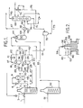
- The invention will be further understood by reference to the accompanying drawing, which includes a schematic representation of a preferred embodiment of the process, and in which:
- Figure 1 is a schematic diagram of the process;
- Figure 2 is a section of a 3 stream burner; and
- Figure 3 is a performance comparison graph.
- The present invention provides an improved partial-oxidation process for producing gaseous mixtures comprising H₂+CO, i.e. synthesis gas, reducing gas or fuel gas. The primary constituents in synthesis gas are H₂ and CO, and the H₂O/CO mole ratio of the synthesis gas is determined by the desired end product. The amount of each gaseous constituent in the product gas determines the use of the gas mixture. Reducing gas is rich in H₂ + CO, but it is lean in H₂O+CO and fuel gas comprises H₂ , CO and CH₄.
- In the process, a hydrocarbon feed gas in admixture with an aqueous dispersion of recycled carbon-soot is introduced into a syngas generator that includes a free-flow vertical refractory-lined reaction zone free from packing and catalyst. In this zone, the feed gas reacts by partial oxidation with a free-oxygen-containing gas which is also introduced into the reaction zone. The temperature in the reaction zone is in the range of about 927°C (1700°F) to about 1316°C (2400°F), such as about 982°C (1800°F) to about 1204°C (2200°F). The pressure in the reaction zone is in the range of about 1 to 250 bar (atmospheres), such as about 15 to 100 bar (atmospheres). The dwell time in the gas generator is about 2.5 to 10 seconds such as about 3 to 6 seconds.
- By definition, the hydrocarbon gas feed to the syngas generator, also referred to as the reactor, is saturated and unsaturated hydrocarbon gases from the group consisting of C₁ to C₆, and mixtures thereof. For example, the hydrocarbon feed gas may comprise from about 40 to 100 volume % CH₄. The sulfur content of the hydrocarbon feed gas may be in the range of about 0 to 400,000 parts per million. Typical hydrocarbon feed gas streams include all of the normally gaseous hydrocarbons and mixtures thereof. Natural gas is a preferred hydrocarbon feed gas. Optionally, a stream of recycle gas may be mixed with the hydrocarbon feed gas. For example, the ratio of recycle gas to hydrocarbon feed gas may be in the range of about 0 to 1, such as about 0.01 to 0.10, parts by volume of recycle gas for each volume of hydrocarbon feed gas. The recycle gas may be any waste gas stream in the system or any off-site gas containing hydrocarbons and/or oxygen, e.g. ammonia-loop purge, cryogenic off-gas.
- The hydrocarbon feed gas stream, with or without said recycle fuel gas, is optionally heated to temperature in the range of about 149°C (300°F) to about 454°C (850°F), such as about 260°C (500°F) to about 427°C (800°F), in a preheater. When the feed gas stream contains more than a few parts per million of sulfur, it may be passed through a guard chamber filled with zinc oxide or other active adsorbent to desulfurize the gas. It is not necessary to desulfurize a feed gas stream which contains sulfur as far as partial oxidation is concerned, but desulfurization is usually advantageous for downstream processes. The partially preheated, and desulfurized if necessary, hydrocarbon gas stream is mixed with a dispersion of recycled soot-H₂O to produce a feed mixture which is preheated to a temperature in the range of about 149°C (300°F) to about 760°C (1400°F) and then introduced into the syngas generator and reacted by partial oxidation with a stream of free-oxygen-containing gas.
- By definition, the term "free-oxygen-containing gas" is a gas selected from air, oxygen-enriched air i.e. more than 21 mole % oxygen, and substantially pure oxygen i.e. at least 95 mole % oxygen. Air is a preferred free-oxygen-containing gas only when large amounts of nitrogen in the syngas can be utilized, tolerated, or economically removed. The O/C ratio (atoms of free oxygen divided by atoms of carbon) in the partial oxidation reaction zone is in the range of about 0.75 to 1.15, depending on the purity of the free-oxygen-containing gas stream and the preheat level of the feed streams. For example, for substantially pure oxygen the O/C atomic ratio is in the range of about 0.75 to 0.95. For air and oxygen enriched air, the O/C atomic ratio is in the range of about 0.85 to 1.15.
- The gaseous composition of the raw effluent gas stream from the raction zone in mole % is as follows: H₂ 10.0 to 68.0, CO 15.0 to 60.0, CO₂ 1.0 to 30.0, H₂O 2.0 to 50.0, CH₄ 0.0 to 28.0, H₂S 0.0 to 20, COS 0.0 to 3.0, N₂ 0.0 to 60.0, Ar 0.0 to 1.8, and NH₃ 0 to 0.02. Also included in the hot effluent gas stream is free-carbon soot in the range of about 0.1 to 3.0 weight percent of the total carbon content of said mixture of hydrocarbon feed gas, recycle soot-water, and recycle gas, if any.
- A more complete understanding of the invention may be had by reference to the accompanying drawing which illustrates a preferred embodiment of the invention, in which a conventional partial-oxidation syngas generator is continuously operated.
- As shown in Figure 1 of the drawing, a hydrocarbon feed gas stream, e.g. natural gas and/or other hydrocarbon gases in line 1 is optionally mixed in
line 2 with a hydrocarbon- and/or hydrogen-containing recycle gas stream fromline 3. For example, the hydrocarbon feed gas and/or hydrocarbon recycle gas stream may comprise about 40 to 100 volume % CH₄. In one embodiment, the stream of recycle gas may contain 0-20 mole % hydrocarbons and is at a temperature in the range of about ambient to 316°C (600°F). The volumetric percent of recycle hydrocarbon- and/or H₂-containing gas in its mixture with the hydrocarbon feed gas is in the range of about 0 to 50, such as about 1 to 10. At ambient temperature the gas fromline 2 is heated in one or more stages to a temperature in the range of about 316°C (600°F) to 760°C (1400°F) in preheater 4 which can be a fired gas heater. Other means for supplying at least a portion of the heat to heat the gas fromline 2 may be used, such as by indirect heat exchange against hot syngas or steam, such as steam that is produced in the synthesis-gas cooler. Optionally, the hydrogen- and/or hydrocarbon-containing recycle stream is a cryogenic off-gas from the gas-purification zone (not shown). For example, in one embodiment, said feed stream of hydrocarbon gas with hydrocarbon- and/or hydrogen-containing recycle gas in (1) comprises at least 20 mole % of hydrocarbons and is at a temperature in the range of about ambient to 316°C (600°F). - The heated mixture of hydrocarbon feed gas in line 6 may be optionally desulfurized by being passed through
line 7, valve 8,line 9, and zinc-oxide-containing desulfurizer 10. The desulfurized gas containing less than one part per million of sulfur is passed out through bottom line 11. Desulfurizer 10 may be a vessel containing zinc oxide or other active adsorbent and may be by-passed by passing the hydrocarbon feed gas stream in line 6 through line 16,valve 17, andline 18. All of the hydrocarbon feed gas stream inlines 11 or 18 is mixed with a pumpable aqueous slurry containing 0.5 to 4 wt. % of carbon soot fromline 19 in mixingvessels line 22, valve 23, line 24 into mixingvessel 21. Simultaneously, the aqueous dispersion of carbon soot inline 19 may be passed throughline 25 into mixingvessel 21. Similarly, the hydrocarbon feed gas stream inline 18 may be passed into mixingvessel 20 by way of line 26,valve 27, andline 28. Alternatively, withvalves 17 and 23 closed the hydrocarbon feed gas stream in line 11 may be passed into mixingvessel 20 by way of lines 35, 26,valve 27 andline 28. Mixingvessels - Mixing
vessels vessels line 36,valve 38,line 39,line 40; or throughline 37,valve 41,line 42, andline 40. Alternatively, mixing of the streams may take place by passing the stream of hydrocarbon feed gas through the main axial passage of a T-mixer, venturi mixer, spray nozzle, mixing vessel or combination thereof while simultaneously passing an aqueous dispersion of carbon soot through at least one other passage in said mixer, which can be perpendicular to said main axial passage. The mixture of hydrocarbon feed gas and aqueous carbon-soot dispersion inline 40 is passed through the coils in preheater 4 and heated to a temperature in the range of about 316°C (600°F) to 760°C (1400°F), such as about 371°C (700°F) to 538°C (1000°F). The heated mixture inline 43 is passed through down-firing burner 44 located in the upper head of partial-oxidation reactor 50. - Simultaneously, a free-oxygen-containing gas stream in
line 51 is heated to a temperature in the range of about ambient to 982°C (1800°F) in firedpreheater 52 and then passed through line 53 andburner 44 into the reaction zone ofgasifier 50. Intimate mixing of the gas streams takes placed at or near the tip ofburner 44. -
Burner 44 maybe a 2-, 3-, or multi-passage burner. For examples of suitable burners, reference is made to U.S. Patent Numbers 3,874,592; 3,847,564; 4,386,941; and 4,443,230. For example, a three-stream burner 55 may be used as shown in Fig. 2.Burner 55 comprisescentral conduit 56, an intermediatecoaxial conduct 57 surrounding said central conduit and forming an annular passage therewith through which said preheated mixture of hydrocarbon feed gas with or without admixture with a hydrocarbon- and/or hydrogen-containing recycle gas stream and a gaseous-phase aqueous dispersion of carbon-soot inline 43 is passed, and an outer coaxialannular passage 58 surrounding said intermediate conduit. The preheated free-oxygen-containing gas in line 53 is split into two separate streams. Onestream 59 passes through thecentral conduit 56, and the other free-oxygen-containinggas stream 60 passes through outerannular passage 58. In a similar embodiment of the subject process, the preheated mixture of hydrocarbon feed gas with or without admixture with a hydrocarbon- and/or hydrogen-containing recycle gas stream is split into two separate streams. One of said streams passes down through said central conduit, and the other of said streams passes through the outer annular passage of the three-stream burner comprising a central conduit, an intermediate annular passage surrounding said central passage, and an outer annular passage surrounding said intermediate annular passage. The stream of free-oxygen-containing gas passes down through said intermediate annular passage. - In still another embodiment employing a three-passage burner, a stream of hydrocarbon feed gas with or without admixture with a hydrocarbon- and/or hydrogen-containing recycle gas stream and preheated to a temperature in the range of about 149°C (300°F) to about 760°C (1400°F), such as about 149°C (300°F) to about 454°C (850°F), is passed through
central conduit 56 or outerannular passage 58. A liquid or gaseous-phase aqueous dispersion comprising 0.5 to 4 wt. % of carbon-soot at a temperature in the range of about ambient to about 760°C (1400°F) is passed through the intermediate annular passage, and a stream of free-oxygen-containing gas at a temperature in the range of about ambient to about 982°C (1800°F) is passed through the remaining free passage in the burner and into the reaction zone of the gas generator. In such case, mixing and heating of the reactants take place in the partial-oxidation gas generator. - In a similar embodiment of the subject process, the feed gas mixture is passed through the intermediate or outer annular passages of a three-passage burner comprising a central passage, a concentric intermediate annular passage, and a concentric outer annular passage. The aqueous dispersion of recycle carbon soot is passed through the central passage; and the stream of free-oxygen-containing gas is passed through the remaining free passage in said burner. The velocity of any gaseous stream passing through the central conduit of a three-stream burner may be in the range of about 15 metres per second (50 feet per second) to sonic velocity. The velocity of any gaseous stream passing through any annular passage in the burner is in the range of about 46 ms⁻¹ (150 feet per second) to sonic velocity. The velocity of an aqueous dispersion of carbon-soot passing through any passage in the burner is about 0.3 to 15 ms⁻¹ (1-50 feet per second) with a liquid-phase dispersion and about 46 ms⁻¹ (150 feet per second) to sonic velocity with a vaporized dispersion.
- The hot effluent gas stream leaving
syngas generator 50 by way ofline 64 at a temperature in the range of about 927°C (1700°F) to about 1316°C (2400°F), such as about 982°C (1800°F) to about 1204°C (2200°F), is cooled to a temperature in the range of about 38°C (100°F) to about 427°C (800°F) by first passing the hot raw effluent gas stream inline 64 through gas cooler 65 in which the hot raw effluent gas stream is cooled to a temperature in the range of about 204°C (400°F) to about 927°C (1700°F) and then by quenching and scrubbing the partially cooled gas stream inline 68 with water in two-stage scrubber 69. The hot raw gas stream is cooled in gas cooler 65 by indirect heat exchange with condensate or boiler-feed water from line 66. By-product high-pressure steam is produced and leaves gas cooler 65 by way ofline 67. Entrained particulate carbon in the partially cooled effluent gas stream inline 68 is removed by scrubbing the gas stream with water in conventional two-stage gas scrubber 69. Cooled soot-free product gas leavesscrubber 69 through line 70 at the top ofgas scrubber 69. A pumpable aqueous dispersion of carbon soot having a solids content in the range of about 0.5 to 4.0 weight percent, such as about 1.0 to 2.0 wt. %, leaves throughline 71 at the bottom ofgas scrubber 69. If necessary to achieve said solids concentration, any suitable means may be used to concentrate the aqueous dispersion of carbon soot inline 71 to a solids content in the range of about 1.0 to 4.0 wt. %. For example, aconventional hydroclone 72 is shown in the drawing. Waste water leaves at the bottom of the hydroclone through line 73. Concentrated aqueous dispersion of carbon soot is removed at the top ofhydroclone 72, and the pumpable concentrated dispersion is recycled to mixingvessels line 19. Alternatively, the soot-water dispersion may be concentrated in two-stage gas scrubber 69 by recycling most of the water from the upper section back to thescrubber orifice 74 by way ofline 75, and pumping only a small quantity of this water into the lower section by way ofline 76. - Under previous operating conditions, partial oxidation of natural gas with air took place at a temperature in the reaction zone of about 1316°C (2400°F) to about 1427°C (2600°F). The Specific Oxygen Consumption (SOC), for example, the standard cubic feet (SCF) of pure oxygen consumed per thousand standard cubic feet (MSCF) of (H₂+CO) produced, was in the range of about 245-270. The related Cold Gas Efficiency (CGE), i.e. high heating value (conveniently expressed in BTU) of H₂ +CO in the product gas divided by the high heating value (BTU) of the hydrocarbon gas feed, was usually in the range of about 83-84%.
- It has been unexpectedly found that, by the improved process, maximum Cold Gas Efficiency (CGE) can be achieved when O/C ratio is decreased and 100% of the resulting increased single-pass spot yield in the product gas is recovered and recycled to extinction in admixture with the hydrocarbon gas feed. Further, the Specific Oxygen Consumption (SOC) is in the range of about 212 to 235, and the temperature in the reaction zone is dropped to the range of about 927°C (1700°F) to about 1316°C (2400°F). The Cold Gas Efficiency of the improved process is increased to a value in the range of about 84.5 to 86.5.
- For the case of air partial oxidation, this improvement can be illustrated by reference to the attached Figure 3, a graph of CGE versus SOC, which are the two parameters, respectively, of consumptions of the two principal raw materials, hydrocarbon feed (natural gas) and oxygen (compressed air). The lower curve C1 represents conventional air partial oxidation of hydrocarbon gases without soot recycle. This curve is generated by successive operating points as feed O/C atomic ratio is increased from left to right. For all points to the left of maximum CGE, CGE decreases as O/C ratio is lowered and more residual methane and unconverted soot (free carbon) are produced. For points to the right of this same maximum, CGE decreases as O/C ratio is raised because, even though methane and carbon are decreasing, the yield of (H₂ + CO) is falling because of more complete oxidation to H₂O + CO₂ The Normal Operating Conditions point N1 for conventional partial oxidation is constrained to a relatively inefficient region, at high O/C and temperature, so that substantially zero soot will be produced.
- The upper curves in C2 and C3 in Figure 3 represent the improved partial-oxidation process of the subject invention with all soot being recycled and the O/C ratio for each point corresponding to the total carbon in both fresh feed and recycle soot. Since all carbon is converted on an overall basis, CGE is always higher for the improved process, except at very high O/C ratios when soot (and methane) production is negligible. To the left of the CGE maxima for the new process, CGE decreases only because of increasing residual methane. As a general correlation, residual methane always increases as (1) temperature falls and (2) residence time in the reaction zone decreases. Best Operating Conditions for the improved process will be at a point N2 and N3 to the left of maximum CGE on each curve. At these optimum points the cost savings in SOC, compared to the SOC at maximum CGE, just balances the losses of CGE compared to its maximum value. The exact location of this optimum-operating-cost point depends, of course, on the relative unit costs (prices) of hydrocarbon feed (natural gas) and oxygen (compressed air), which are the principal two raw materials.
- Further, it has been unexpectedly found in the improved process that by increasing the volume of the reaction zone, up to a limit set by excessive heat loss from this zone, the Cold Gas Efficiency is increased, the Specific Oxygen Consumption is reduced, and the temperature in the reaction zone is reduced. For example, if the volume of the reaction zone is 25.5 m³ (900 cu. ft.) for air partial oxidation of a hydrocarbon gas with all feed conditions held constant, by operating in a 34 m³ (1200 cu. ft.) reaction zone, i.e. an increase of 33¹/₃%, the Cold Gas Efficiency is increased from about 84.4 to 86.6%, the Specific Oxygen Consumption is reduced from about 230 to 215, and the temperature in the reaction zone is reduced from about 1124°C (2056°F) to about 1054°C (1930°F). Advantageously, the volume of the reaction zone for the improved process may be increased in comparison with the volume of the reaction zone for conventional partial oxidation. Typically, this beneficial increase may be in the range of about 10-100% greater. This larger volume may be determined by conventional methods of calculation. Some principles are described in U.S. Patent No. 2,582,938. An increase in volume of the reaction zone contributes to the increase in dwell time but also increases heat loss and lowers temperature. Accordingly, whereas the conventional dwell time in the reaction zone of the partial-oxidation reactor is in the range of about 2 0 to 5 seconds for the partial oxidation of a hydrocarbon gas, e.g. methane, the preferred dwell time in the improved process is in the range of about 2.5 to 10 seconds, in order to minimize residual methane. Thus the volume of the partial-oxidation reaction zone in the subject improved process may be greater than the volume of the reaction zone for conventional partial oxidation by an amount which provides sufficient residence time to reduce residual methane in the raw effluent gas stream from the reaction zone to the minimum achiev able at the lower feed O/C atomic ratio but with all other independent variables held constant.
- Beyond the simple optimization indicated above of raw-material costs alone, it is possible to optimize the improved process fully with respect to both operating and fixed costs, as outlined below:

- To optimize both design and operation, all of the above costs are calculated for two or three points near the Best Operating Conditions point for the improved process with a given reactor volume in Figure 3. By repeating this calculation procedure for at least two other reaction volumes, it is possible to select the optimum design and operating conditions.
- In one embodiment of the subject process raw materials may be optimized by adjusting the feed oxygen/carbon ratio (O/C = number of atoms of free oxygen in the oxidant stream divided by number of atoms of carbon in the stream of fresh hydrocarbon feed gas plus recycle soot-water plus recycle hydrocarbon and/or hydrogen-containing gas) so that the resulting specific oxygen consumption and cold-gas efficiency lead to a minimum for the total cost of oxidant (air, oxygen-enriched air, or substantially pure oxygen) plus hydrocarbon feed gas per unit volume of (H₂ + CO) produced. Further, the total operating cost may be optimized by adjusting the feed O/C ratio so that the total net cost of the oxidant stream plus the hydrocarbon feed gas stream plus utilit ies (primarily preheat fuel but including input steam, electricity, cooling water, and any others) plus any other operating requirements (such as operating manpower) minus a credit for export steam is minimized per unit volume of (H₂ + CO) produced. Also, the design of the process unit may be optimized by selecting the design value of feed O/C so that, per unit volume (H₂ + CO) produced, the net total of all operating costs plus all investment costs (such as for feed and preheating equipment, burner fabrication, reactor volume, gas-cooling and quenching equipment, and soot-recovery and recycle equipment) is minimized. In some cases, there may be a fixed upper limit for effluent methane concentration, determined by downstream-process requirements. For these cases, the feed O/C can be reduced only to a value which keeps exit methane at or below that limit, so the optimization is still carried out but only down to the lowest O/C allowed by such methane limit.
- The following example illustrates a preferred embodiment of this invention for the case of using air as oxidant.
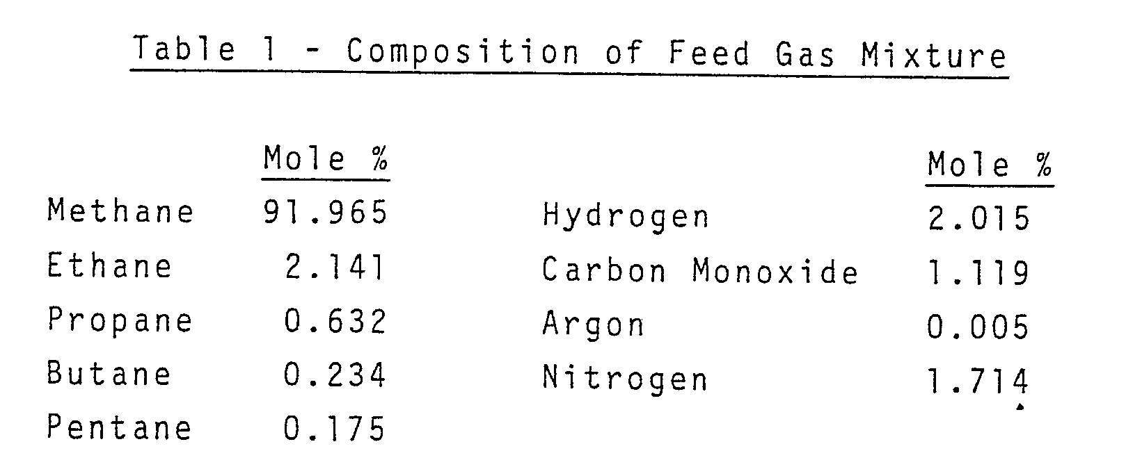
- 9.45 × 10⁹ m³ (33,376,000 Standard Cubic Feet) per day, measured at 16°C (60°F) and a gauge pressure of 1.10⁵ Pa (14.7 psig), of a mixture comprising natural gas and hydrocarbon-containing recycle gas from the ammonia-loop purge of a downstream process are mixed together and preheated to a temperature of about 371°C (700°F) in a fired gas preheater. The composition of the feed gas mixture of natural gas plus recycle gas is shown in Table 1 in mol %:
- The preheated feed gas mixture is mixed in a mixing vessel with 6.96 × 10³ Kg (15,337 pounds) per hr. of recycle soot-water dispersion having a solids content of 1.0% and a temperature of 121°C (250°F). The mixture is then preheated in a fired gas preheater to produce a dispersion of soot in gas having a temperature of 566°C (1050°F) and comprising completely vaporized slurry water and completely dispersed soot particles in natural gas and recycle gas at a gauge pressure of 34.5 × 10⁵ Pa (500 psig).
- The particulate-carbon natural-gas feed dispersion is passed through the intermediate annular passage of a burner comprising a central conduit, an intermediate annular passage surrounding said central conduit, and an outer annular passage surrounding said intermediate passage. Simultaneously 7.64 × 10⁵ Kg (842 short tons) per operating day of 100% oxygen contained in air having the composition in mol % shown in Table 2 below and at a temperature of 788°C (1450°F) are split into two streams and passed through the central conduit and the outer annular passage of said burner at a gauge pressure of 34.5 × 10⁵ Pa (500 psig).

- 5.15 × 10¹⁰ m (181,742,000 standard cubic feet) per operating day of raw effluent synthesis gas (wet basis) are discharged from the free-flow refractory-lined reaction zone in which the partial oxidation takes place at a temperature of 1124°C (2056°F) and a gauge pressure of 3.24 × 10⁶ Pa (470 psig).
- The raw effluent gas stream is passed through a gas cooler and cooled to a temperature of 328°C (623°F) by indirect heat exchange with boiler-feed water. Steam is thereby produced having a temperature of 317°C (603°F) and a gauge pressure of 1.08 × 10⁷ Pa (1560 psig). The partially cooled raw effluent gas stream is scrubbed with water in a conventional two-stage soot scrubber. 69 Kg (153 pounds) per hr. of soot (unreacted carbon) are removed from the gas stream and form a dispersion with the scrubbing water. The resulting aqueous dispersion of soot comprising 1.0 wt. % of solids is recycled for admixture with the mixture of natural gas plus hydrocarbon- and/or hydrogen-containing recycle gas. Optionally, the soot-water stream may be concentrated in a hydroclone to about 3 wt. %. This concentration, in whatever equipment, is made as high as possible while still maintaining pumpability in order to increase efficiency by minimizing the amount of water to be vaporized. The composition of the soot-free synthesis gas produced is shown in Table 3 below.

Claims (10)
Applications Claiming Priority (2)
| Application Number | Priority Date | Filing Date | Title |
|---|---|---|---|
| US947185 | 1986-12-29 | ||
| US06/947,185 US4699631A (en) | 1986-12-29 | 1986-12-29 | Partial oxidation of hydrocarbon gases |
Publications (3)
| Publication Number | Publication Date |
|---|---|
| EP0276538A2 true EP0276538A2 (en) | 1988-08-03 |
| EP0276538A3 EP0276538A3 (en) | 1989-12-27 |
| EP0276538B1 EP0276538B1 (en) | 1993-02-17 |
Family
ID=25485683
Family Applications (1)
| Application Number | Title | Priority Date | Filing Date |
|---|---|---|---|
| EP87308487A Expired - Lifetime EP0276538B1 (en) | 1986-12-29 | 1987-09-25 | Partial oxidation of hydrocarbon gases |
Country Status (6)
| Country | Link |
|---|---|
| US (1) | US4699631A (en) |
| EP (1) | EP0276538B1 (en) |
| AU (1) | AU597118B2 (en) |
| CA (1) | CA1283781C (en) |
| DE (1) | DE3784237T2 (en) |
| NO (1) | NO172486C (en) |
Cited By (4)
| Publication number | Priority date | Publication date | Assignee | Title |
|---|---|---|---|---|
| EP0325469A3 (en) * | 1988-01-22 | 1991-12-18 | Spectra-Physics, Inc. | Automatic package label scanner |
| EP0565274A1 (en) * | 1992-03-25 | 1993-10-13 | Eli Lilly And Company | 5-Ht1A agonists for improving primary memory and/or learning |
| EP1209214A3 (en) * | 2000-11-21 | 2003-10-08 | Yukuo Katayama | Method for the gasification of coal |
| WO2003084867A1 (en) * | 2002-04-08 | 2003-10-16 | Guy-Marie Come | Method and implementing apparatuses using free radicals for triggering a conversion reaction of hydrocarbon feedstock into synthetic gas |
Families Citing this family (9)
| Publication number | Priority date | Publication date | Assignee | Title |
|---|---|---|---|---|
| GB8711156D0 (en) * | 1987-05-12 | 1987-06-17 | Shell Int Research | Partial oxidation of hydrocarbon-containing fuel |
| CA2100811C (en) * | 1992-08-19 | 1999-01-19 | Akhilesh Kapoor | Hydrogen and carbon monoxide production by partial oxidation of hydrocarbon feed |
| DE69925754T2 (en) * | 1998-11-16 | 2006-03-23 | Texaco Development Corp. | PARTIAL OXIDIZATION METHOD WITH RECOVERY OF PEPPER MASSES |
| EP1135451A4 (en) * | 1998-11-16 | 2002-05-15 | Texaco Development Corp | Removal of soot in a gasification system |
| US6641625B1 (en) | 1999-05-03 | 2003-11-04 | Nuvera Fuel Cells, Inc. | Integrated hydrocarbon reforming system and controls |
| US6713657B2 (en) | 2002-04-04 | 2004-03-30 | Chevron U.S.A. Inc. | Condensation of olefins in fischer tropsch tail gas |
| JP2006502938A (en) | 2002-06-13 | 2006-01-26 | ヌヴェラ フューエル セルズ インコーポレイテッド | Preferential oxidation reactor temperature control |
| US7074375B2 (en) * | 2002-12-03 | 2006-07-11 | Engelhard Corporation | Method of desulfurizing a hydrocarbon gas by selective partial oxidation and adsorption |
| DE102007026923A1 (en) * | 2007-06-12 | 2008-12-18 | Enerday Gmbh | Two-stage gas reformer |
Family Cites Families (15)
| Publication number | Priority date | Publication date | Assignee | Title |
|---|---|---|---|---|
| US1971728A (en) * | 1934-08-28 | Process of reforming oil gas | ||
| US2701756A (en) * | 1955-02-08 | Manufacture of synthesis gas | ||
| US2483132A (en) * | 1946-02-21 | 1949-09-27 | Texas Co | Conversion of hydrocarbon gas into carbon monoxide and hydrogen |
| US2701757A (en) * | 1946-12-17 | 1955-02-08 | Texaco Development Corp | Process of making synthesis gas |
| US2491518A (en) * | 1947-04-11 | 1949-12-20 | Hydrocarbon Research Inc | Generation of synthesis gas |
| US2668754A (en) * | 1950-02-23 | 1954-02-09 | Columbian Carbon | Process for recovering carbon black from a gaseous suspension |
| US2702238A (en) * | 1950-11-20 | 1955-02-15 | Phillips Petroleum Co | Apparatus for controlling synthesis reactions |
| US2941877A (en) * | 1957-07-01 | 1960-06-21 | Texaco Development Corp | Hydrocarbon conversion process |
| US2987386A (en) * | 1958-05-29 | 1961-06-06 | Texaco Inc | Production of carbon monoxide and hydrogen |
| US3232728A (en) * | 1961-12-13 | 1966-02-01 | Texaco Development Corp | Synthesis gas generation |
| US3232727A (en) * | 1961-12-13 | 1966-02-01 | Texaco Inc | Synthesis gas generation |
| US3528930A (en) * | 1968-05-29 | 1970-09-15 | Texaco Inc | Production of synthesis gas |
| US3884648A (en) * | 1972-06-28 | 1975-05-20 | Texaco Inc | Process for making a reducing gas |
| US4016104A (en) * | 1974-12-23 | 1977-04-05 | Texaco Development Corporation | Recovery of particulate carbon from synthesis gas |
| US4411670A (en) * | 1982-06-07 | 1983-10-25 | Texaco Development Corporation | Production of synthesis gas from heavy hydrocarbon fuels containing high metal concentrations |
-
1986
- 1986-12-29 US US06/947,185 patent/US4699631A/en not_active Expired - Fee Related
-
1987
- 1987-09-25 EP EP87308487A patent/EP0276538B1/en not_active Expired - Lifetime
- 1987-09-25 DE DE8787308487T patent/DE3784237T2/en not_active Expired - Fee Related
- 1987-10-08 CA CA000548849A patent/CA1283781C/en not_active Expired - Fee Related
- 1987-10-16 AU AU79873/87A patent/AU597118B2/en not_active Ceased
- 1987-10-26 NO NO874447A patent/NO172486C/en unknown
Cited By (4)
| Publication number | Priority date | Publication date | Assignee | Title |
|---|---|---|---|---|
| EP0325469A3 (en) * | 1988-01-22 | 1991-12-18 | Spectra-Physics, Inc. | Automatic package label scanner |
| EP0565274A1 (en) * | 1992-03-25 | 1993-10-13 | Eli Lilly And Company | 5-Ht1A agonists for improving primary memory and/or learning |
| EP1209214A3 (en) * | 2000-11-21 | 2003-10-08 | Yukuo Katayama | Method for the gasification of coal |
| WO2003084867A1 (en) * | 2002-04-08 | 2003-10-16 | Guy-Marie Come | Method and implementing apparatuses using free radicals for triggering a conversion reaction of hydrocarbon feedstock into synthetic gas |
Also Published As
| Publication number | Publication date |
|---|---|
| AU7987387A (en) | 1988-06-30 |
| US4699631A (en) | 1987-10-13 |
| DE3784237D1 (en) | 1993-03-25 |
| AU597118B2 (en) | 1990-05-24 |
| EP0276538B1 (en) | 1993-02-17 |
| EP0276538A3 (en) | 1989-12-27 |
| DE3784237T2 (en) | 1993-05-27 |
| NO172486C (en) | 1993-07-28 |
| NO172486B (en) | 1993-04-19 |
| NO874447D0 (en) | 1987-10-26 |
| NO874447L (en) | 1988-06-30 |
| CA1283781C (en) | 1991-05-07 |
Similar Documents
| Publication | Publication Date | Title |
|---|---|---|
| US6527980B1 (en) | Reforming with intermediate reactant injection | |
| US3278452A (en) | Production of hydrogen-containing gases | |
| AU610341B2 (en) | Methanol | |
| US5358696A (en) | Production of H2 -rich gas | |
| US4973453A (en) | Apparatus for the production of heavier hydrocarbons from gaseous light hydrocarbons | |
| AU742314B2 (en) | Steam reforming | |
| EP0276538B1 (en) | Partial oxidation of hydrocarbon gases | |
| US4081253A (en) | Production of purified synthesis gas and carbon monoxide | |
| US4618451A (en) | Synthesis gas | |
| US4676805A (en) | Process for operating a gas generator | |
| NO153564B (en) | PROCEDURE FOR THE PREPARATION OF SYNTHESIC GAS FROM A SULFULATED HYDROCARBON CONTAINING CHARGE. | |
| US3388074A (en) | Two-stage steam reforming with rapid warm-up in first stage by means of a promoted catalyst | |
| WO1998007652A2 (en) | Process for abatement of nitrogen oxides in exhaust from gas turbine power generation | |
| CA1241666A (en) | Process for the preparation of methanol | |
| JPH1143306A (en) | Obtaining carbon monoxide and hydrogen | |
| JP3302363B2 (en) | Method for producing high-purity carbon monoxide | |
| US3545926A (en) | Production of synthesis gas and hydrogen | |
| AU694052B2 (en) | A method for producing hydrogen-carbon monoxide mixed gas, and apparatus thereof | |
| US3759679A (en) | Production of methane rich fuel gas | |
| JP2007536347A (en) | Methanol synthesis system and method | |
| US3846095A (en) | Reducing gas generation | |
| EP0207620B1 (en) | Energy recovery | |
| US3927999A (en) | Methane-rich gas process | |
| EP0086504B1 (en) | A process for generating mechanical power | |
| US3927997A (en) | Methane-rich gas process |
Legal Events
| Date | Code | Title | Description |
|---|---|---|---|
| PUAI | Public reference made under article 153(3) epc to a published international application that has entered the european phase |
Free format text: ORIGINAL CODE: 0009012 |
|
| AK | Designated contracting states |
Kind code of ref document: A2 Designated state(s): DE FR GB NL |
|
| PUAL | Search report despatched |
Free format text: ORIGINAL CODE: 0009013 |
|
| AK | Designated contracting states |
Kind code of ref document: A3 Designated state(s): DE FR GB NL |
|
| 17P | Request for examination filed |
Effective date: 19900605 |
|
| 17Q | First examination report despatched |
Effective date: 19910206 |
|
| GRAA | (expected) grant |
Free format text: ORIGINAL CODE: 0009210 |
|
| AK | Designated contracting states |
Kind code of ref document: B1 Designated state(s): DE FR GB NL |
|
| REF | Corresponds to: |
Ref document number: 3784237 Country of ref document: DE Date of ref document: 19930325 |
|
| ET | Fr: translation filed | ||
| PLBE | No opposition filed within time limit |
Free format text: ORIGINAL CODE: 0009261 |
|
| STAA | Information on the status of an ep patent application or granted ep patent |
Free format text: STATUS: NO OPPOSITION FILED WITHIN TIME LIMIT |
|
| 26N | No opposition filed | ||
| PG25 | Lapsed in a contracting state [announced via postgrant information from national office to epo] |
Ref country code: NL Effective date: 19940401 |
|
| NLV4 | Nl: lapsed or anulled due to non-payment of the annual fee | ||
| PGFP | Annual fee paid to national office [announced via postgrant information from national office to epo] |
Ref country code: FR Payment date: 19940615 Year of fee payment: 8 |
|
| PGFP | Annual fee paid to national office [announced via postgrant information from national office to epo] |
Ref country code: GB Payment date: 19940627 Year of fee payment: 8 |
|
| PGFP | Annual fee paid to national office [announced via postgrant information from national office to epo] |
Ref country code: DE Payment date: 19940930 Year of fee payment: 8 |
|
| PG25 | Lapsed in a contracting state [announced via postgrant information from national office to epo] |
Ref country code: GB Effective date: 19950925 |
|
| GBPC | Gb: european patent ceased through non-payment of renewal fee |
Effective date: 19950925 |
|
| PG25 | Lapsed in a contracting state [announced via postgrant information from national office to epo] |
Ref country code: FR Effective date: 19960531 |
|
| PG25 | Lapsed in a contracting state [announced via postgrant information from national office to epo] |
Ref country code: DE Effective date: 19960601 |
|
| REG | Reference to a national code |
Ref country code: FR Ref legal event code: ST |