EP0276532B1 - Valve operating mechanism for internal combustion engine - Google Patents
Valve operating mechanism for internal combustion engine Download PDFInfo
- Publication number
- EP0276532B1 EP0276532B1 EP87300859A EP87300859A EP0276532B1 EP 0276532 B1 EP0276532 B1 EP 0276532B1 EP 87300859 A EP87300859 A EP 87300859A EP 87300859 A EP87300859 A EP 87300859A EP 0276532 B1 EP0276532 B1 EP 0276532B1
- Authority
- EP
- European Patent Office
- Prior art keywords
- cam
- speed
- low
- valve
- cams
- Prior art date
- Legal status (The legal status is an assumption and is not a legal conclusion. Google has not performed a legal analysis and makes no representation as to the accuracy of the status listed.)
- Expired - Lifetime
Links
Images


Classifications
-
- F—MECHANICAL ENGINEERING; LIGHTING; HEATING; WEAPONS; BLASTING
- F01—MACHINES OR ENGINES IN GENERAL; ENGINE PLANTS IN GENERAL; STEAM ENGINES
- F01L—CYCLICALLY OPERATING VALVES FOR MACHINES OR ENGINES
- F01L1/00—Valve-gear or valve arrangements, e.g. lift-valve gear
- F01L1/26—Valve-gear or valve arrangements, e.g. lift-valve gear characterised by the provision of two or more valves operated simultaneously by same transmitting-gear; peculiar to machines or engines with more than two lift-valves per cylinder
- F01L1/267—Valve-gear or valve arrangements, e.g. lift-valve gear characterised by the provision of two or more valves operated simultaneously by same transmitting-gear; peculiar to machines or engines with more than two lift-valves per cylinder with means for varying the timing or the lift of the valves
-
- F—MECHANICAL ENGINEERING; LIGHTING; HEATING; WEAPONS; BLASTING
- F02—COMBUSTION ENGINES; HOT-GAS OR COMBUSTION-PRODUCT ENGINE PLANTS
- F02D—CONTROLLING COMBUSTION ENGINES
- F02D13/00—Controlling the engine output power by varying inlet or exhaust valve operating characteristics, e.g. timing
- F02D13/02—Controlling the engine output power by varying inlet or exhaust valve operating characteristics, e.g. timing during engine operation
- F02D13/06—Cutting-out cylinders
-
- Y—GENERAL TAGGING OF NEW TECHNOLOGICAL DEVELOPMENTS; GENERAL TAGGING OF CROSS-SECTIONAL TECHNOLOGIES SPANNING OVER SEVERAL SECTIONS OF THE IPC; TECHNICAL SUBJECTS COVERED BY FORMER USPC CROSS-REFERENCE ART COLLECTIONS [XRACs] AND DIGESTS
- Y02—TECHNOLOGIES OR APPLICATIONS FOR MITIGATION OR ADAPTATION AGAINST CLIMATE CHANGE
- Y02T—CLIMATE CHANGE MITIGATION TECHNOLOGIES RELATED TO TRANSPORTATION
- Y02T10/00—Road transport of goods or passengers
- Y02T10/10—Internal combustion engine [ICE] based vehicles
- Y02T10/12—Improving ICE efficiencies
Definitions
- the present invention relates to a valve operating mechanism for an internal combustion engine, including a camshaft rotatable in synchronism with the rotation of the internal combustion engine and having integral cams for operating an intake or exhaust valve, and rocker arms or cam followers angularly movably supported on a rocker shaft for opening and closing the intake or exhaust valve in response to rotation of the cams.
- Valve operating mechanisms used in internal combustion engines are generally designed to meet requirements for high-speed operation of the engines.
- the valve diameter and valve lift are selected to efficiently introduce an air-fuel mixture required to produce maximum engine power in a certain engine speed range.
- the coupling means consists of complementary steps provided on the adjacent side faces of the cam followers, and in order to bring about the selective interconnection or disconnection it is necessary axially to move one of the cam followers to engage with or disengage from the other cam follower.
- a valve operating mechanism for operating a single valve of a particular cylinder of an internal combustion engine, comprising: a camshaft rotatable in synchronism with rotation of the internal combustion engine; a plurality of cams on said camshaft with each of said cams having a different cam profile and including a high-speed cam; a plurality of cam followers each of which slidably engages a respective cam for selectively operating the valve according to the cam profile of said cam, and one of said cam followers engaging said valve; and coupling means for selectively interconnecting and disconnecting said cam followers to operate the valve differently in different speed ranges of the internal combustion engine; characterised in that an asymmetrical array of three cams is provided on the camshaft, the high-speed cam being positioned at one end of the array, there being three cam followers slidably engaging said three cams, respectively.
- the camshaft may have an annular raised portion and low- and high-speed cams, or low-, medium-, and high-speed cams, and the cam followers are held in sliding contact with these raised portion and cams.
- the valve is selectively kept inoperative by the raised portion and operated in low- and high-speed ranges by the low-and high-speed cams, or selectively operated in low-, medium-, and high-speed ranges by the low-, medium-, and high-speed cams.
- the three cam followers are pivotally mounted in an axially fixed location on a fixed cam follower shaft to pivot about a fixed axis.
- FIGS. 1 and 2 show a valve operating mechanism according to an embodiment of the present invention.
- the valve operating mechanism is incorporated in a particular engine cylinder of an internal combustion engine including a single intake valve 1 for introducing an air-fuel mixture into a combustion chamber defined in an engine body.
- the valve operating mechanism comprises a cam-shaft 2 rotatable in synchronism with rotation of the engine at a speed ratio of 1/2 with respect to the speed of rotation of the engine.
- the camshaft 2 has an annular raised portion 3, a low-speed cam 4, and a high-speed cam 5 which are integrally disposed on the circumference of the camshaft 2.
- the valve operating mechanism also has a rocker shaft 6 extending parallel to the camshaft 2, and first to third rocker arms or cam followers 7, 8, 9 angularly movably supported on the rocker shaft 6 and held against the raised portion 3, the low-speed cam 4, and the high-speed cam 5, respectively, on the camshaft 2.
- the intake valve 1 is selectively operated by the first to third cam followers 7, 8, 9 actuated by the low- and high-speed cams 4, 5.
- the camshaft 2 is rotatably disposed above the engine body.
- the raised portion 3 is disposed in a position above the intake valve 1.
- the low-speed cam 4 and the high-speed cam 5 are disposed one on each side of the raised portion 3.
- the raised portion 3 has a circumferential profile in the shape of a circle corresponding to the base circles 4b, 5b of the low- and high-speed cams 4, 5.
- the low-speed cam 4 has a cam lobe 4a projecting radially outwardly from the base circle 4b
- the high-speed cam 5 has a cam lobe 5a projecting radially outwardly from the base circle 5b to a greater extent than the cam lobe 4a, the cam lobe 5a having a larger angular extent than the cam lobe 4a.
- the rocker shaft 6 is fixed below the camshaft 2.
- the first cam follower 7 pivotally supported on the rocker shaft 6 is aligned with the raised portion 3
- the second cam follower 8 pivotally supported on the rocker shaft 6 is aligned with the low-speed cam 4
- the third cam follower 9 pivotally supported on the rocker shaft 6 is aligned with the high-speed cam 5.
- the cam followers 7, 8, 9 have on their upper surfaces cam slippers 7a, 8a, 9a, respectively, held in sliding contact with the raised portion 3 and the cams 4, 5, respectively.
- the first cam follower 7 has a distal end positioned above the intake valve 1.
- a tappet screw 12 is threaded through the distal end of the first cam follower 7 and has a tip engagable with the upper end of the valve stem of the intake valve 1.
- a flange 14 is attached to the upper end of the valve stem of the intake valve 1.
- the intake valve 1 is normally urged to close the intake port by a compression coil spring 16 disposed under compression around the valve stem between the flange 14 and the engine body.
- a bottomed cylindrical lifter 19 is disposed in abutment against a lower surface of the second cam follower 8.
- the lifter 19 is normally urged upwardly by a compression spring 20 of relatively weak resiliency interposed between the lifter 19 and the engine body for resiliently biasing the cam slipper 8a of the second cam follower 8 slidably against the low-speed cam 4.
- first and second cam followers 7, 8 have confronting side walls held in sliding contact with each other.
- a first selective coupling 21 is operatively disposed in and between the first and second cam followers 7, 8 for selectively disconnecting the cam followers 7, 8 from each other for relative displacement and also for interconnecting the cam folowers 7, 8 for their movement in unison.
- the first and third cam followers 7, 9 have confronting side walls held in sliding contact with each other.
- a second selective coupling 22 is operatively disposed in and between the first and third cam followers, 7, 9 for selectively disconnecting the cam followers 7, 9 from each other for relative displacement and also for interconnecting the cam followers 7, 9 for their movement in unison.
- the first and second selective couplings 21, 22 are of an identical construction, and hence only the first selective coupling 21 will hereinafter be described in detail.
- the first selective coupling 21 comprises a piston 23 movable between a position in which it interconnects the first and second cam followers 7, 8 and a position in which it disconnects the first and second cam followers 7, 8 from each other, a circular stopper 24 for limiting the movement of the piston 23, and a coil spring 25 for urging the stopper 24 to move the piston 23 toward the position to disconnect the first and second cam followers 7, 8 from each other.
- the first cam follower 7 has a first guide hole 26 opening toward the second cam follower 8 and extending parallel to the rocker shaft 6.
- the first cam follower 7 also has a smaller-diameter hole 28 near the closed end of the first guide hole 26, with a step or shoulder 27 being defined between the smaller-diameter hole 28 and the first guide hole 26.
- the piston 23 is slidably fitted in the first guide hole 26.
- the piston 23 and the closed end of the smaller-diameter hole 28 define therebetween a hydraulic pressure chamber 29.
- the first cam follower 7 has a hydraulic passage 30 defined therein in communication with the hydraulic pressure chamber 29.
- the rocker shaft 6 has a hydraulic passage 31 defined axially therein and coupled to a source (not shown) of hydraulic pressure through a suitable hydraulic pressure control mechanism.
- the hydraulic passages 30, 31 are held in communication with each other through a hole 32 defined in a side wall of the rocker shaft 6, irrespective of how the first cam follower 7 is angularly moved about the rocker shaft 6.
- the second cam follower 8 has a second guide hole 35 opening toward the first cam follower 7 in registration with the first guide hole 26 in the first cam follower 7.
- the circular stopper 24 is slidably fitted in the second guide hole 35.
- the second cam follower 8 also has a smaller-diameter hole 37 near the closed end of the second guide hole 35, with a step or shoulder 36 defined between the second guide hole 35 and the smaller-diameter hole 37 for limiting movement of the circular stopper 24.
- the second cam follower 8 also has a through hole 38 defined coaxially with the smaller-diameter hole 37.
- a guide rod 39 joined integrally and coaxially to the circular stopper 24 extends through the hole 38.
- the coil spring 25 is disposed around the guide rod 39 between the stopper 24 and the closed end of the smaller-diameter hole 37.
- the piston 23 has an axial length selected such that when one end of the piston 23 abuts against the step 27, the other end thereof is positioned just between and hence lies flush with the sliding side walls of the first and second cam followers 7, 8, and when the piston 23 is moved into the second guide hole 35 until it displaces the stopper 24 into abutment against the step 36, said one end of the piston 23 remains in the first guide hole 26 and hence the piston 23 extends between the first and second cam followers 7, 8.
- the hydraulic passages 31 communicating with the first and second selective coupling 21, 22 are isolated from each other by a steel ball 33 forcibly fitted and fixedly positioned in the rocker shaft 6. Therefore, the first and second selective couplings 21, 22 are operable under hydraulic pressure independently of each other.
- the first and second selective couplings 21, 22 are actuated to disconnect the first to third cam followers 7, 8, 9 from each other as illustrated in FIG. 4. More specificially, the hydraulic pressure is released by the hydraulic pressure control mechanism from the hydraulic pressure chamber 29, thus allowing the stopper 24 to move toward the first cam follower 7 under the resiliency of the spring 25 until the piston 23 abuts against the step 27.
- the piston 23 engages the step 27 the mutually contacting ends of the piston 23 and the stopper 24 of the first selective coupling 21 lie flush with the sliding side walls of the first and second cam followers 7, 8.
- first, second, and third cam followers 7, 8, 9 are held in mutually sliding contact for relative angular movement.
- the first cam follower 7 is not affected by the angular movement of the second and third cam followers 8, 9 in sliding contact with the low- and high-speed cams 4, 5.
- the first cam follower 7 does not pivot as the raised portion 3 imposes no camming action thereon. Any frictional loss of the valve operating mechanism is relatively low because the second cam follower 8 is held in sliding contact with with low-speed cam 4 under the relatively small resilient force of the spring 20.
- the intake valve 1 remains closed, thus reducing fuel consumption.
- the first and second cam followers 7, 8 are interconnected by the first selective coupling 21, with the first and third cam followers 7, 9 remaining disconnected from each other, as shown in FIG. 5. More specifically, the hydraulic pressure chamber 29 of the first selective coupling 21 is supplied with hydraulic pressure to cause the piston 23 to push the stopper 24 into the second guide hole 35 against the resiliency of the spring 25 until the stopper 24 engages the step 36. The first and second cam followers 7, 8 are now connected to each other for angular movement in unison.
- the intake valve 1 alternately opens and closes the intake port at the valve timing and valve lift according to the profile of the low-speed cam 4.
- the air fuel mixture now flows into the combustion chamber at a rate suitable for the low-speed operation of the engine, resulting in good fuel economy and knocking prevention.
- the first and third cam followers 7, 9 are interconnected by the second selective coupling 22, as shown in FIG. 6, by supplying hydraulic pressure into the hydraulic-pressure chamber 29 of the second selective coupling 22.
- the first and second cam followers 7, 8 may remain connected by the first selective coupling 21 or may be disconnected thereby.
- the first cam follower 7 is caused to pivot with the third cam follower 9.
- the intake valve 1 alternately opens and closes the intake port at the valve timing and valve lift according to the profile of the high-speed cam 5. The intake efficiency is increased to enable the engine to produce higher output power and torque.
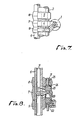
- FIG. 7 shows another embodiment of the present invention in which the low-speed cam 4 is disposed between the high-speed cam 5 and the raised portion 3.
- the first and second cam followers 7, 8 are held in sliding contact with the low- and high-speed cams, 4, 5, respectively, whereas the third cam follower 9 slidingly contacts the raised portion 3, the third cam follower 9 being engageable with the intake valve 1.
- the first and second selective couplings 21, 22 are operated as shown in FIG. 4, and hence the cam followers 7, 8, 9 are independently pivotable, allowing the intake valve 1 to remain closed.
- the first and third cam followers 7, 9 are interconnected and the first and second cam followers 7, 8 remain disconnected by operating the first and second selective couplings 21, 22 as shown in FIG. 8. Therefore, the intake valve 1 is controlled according to the cam profile of the low-speed cam 4.
- the cam followers 7, 8, 9 are interconnected as shown in FIG. 6 to cause the intake valve 1 to operate according to the cam profile of the high-speed cam 5.
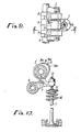
- FIGS. 9 and 10 show still another embodiment of the present invention.
- the camshaft 2 supports thereon a low-speed cam 3', a medium-speed cam 4, and a high-speed cam 5 which have cam lobes 3a, 4a, 5a, respectively.
- the cam lobe 5a is larger in radial projection and angular extent than the cam lobe 4a, which in turn is larger in radial projection and angular extent than the cam lobe 3a.
- the first cam follower 7, which is engageable with the intake valve 1, is held in sliding contact with the low-speed cam 3', while the second and third cam followers 8, 9 are held in sliding contact with the medium- and high-speed cams 4, 5.
- the cam followers 7, 8, 9 are disconnected from each other, as shown in FIG. 4, and the intake level 1 is operated according to the cam profile of the low-speed cam 3'.
- the first and second cam followers 7, 8 are interconnected and the first and third cam followers 7, 9 remain disconnected, as shown in FIG. 5, causing the intake valve 1 to be operated by the medium-speed cam 4.
- the cam followers 7, 8, 9 are interconnected, as shown in FIG. 6, or only the first and third cam followers 7, 9 are interconnected, as shown in FIG. 8, for thereby enabling the intake valve 1 to be controlled by the high-speed cam 5.
- the medium-speed cam 4 is positioned between the low- and high-speed cams 3', 5.
- the first and second cam followers 7, 8 are kept in sliding contact with the medium- and high-speed cams 4, 5.
- the low-speed cam 3' is slidingly engaged by the third cam follower 9 which is engageable with the intake valve 1.
- the cam followers 7, 8, 9 are disconnected, as shown in FIGS. 4, and the intake valve 1 is controlled by the low-speed cam 3'.
- the first and third cam followers 7, 9 are interconnected, and the first and second cam followers 7, 8 remain disconnected,as shown in FIG. 8, to operate the intake valve 1 according to the cam profile of the medium-speed cam 4.
- all of the cam followers 7, 8, 9 are interconnected, as shown in FIG. 6, to control the intake valve 1 according to the cam profile of the high-speed cam 5.
- an exhaust valve may also be operated by the valve operating mechanisms according to the present invention.
- unburned components due to exhaust gas turbulence can be reduced in low-speed operation of the engine, whereas high engine output power and torque can be generated by reducing resistance to the flow of an exhaust gas from the combustion chamber in high-speed operation of the engine.
- the present invention provides a valve operating mechanism for an internal combustion engine, which controls a valve in low- medium- and high-speed ranges for increased engine power and fuel economy; and furthermore provides a valve operating mechanism which is of a relatively simple structure, for making the intake or exhaust valve of a particular engine cylinder inoperative for better fuel economy.
Description
- The present invention relates to a valve operating mechanism for an internal combustion engine, including a camshaft rotatable in synchronism with the rotation of the internal combustion engine and having integral cams for operating an intake or exhaust valve, and rocker arms or cam followers angularly movably supported on a rocker shaft for opening and closing the intake or exhaust valve in response to rotation of the cams.
- Valve operating mechanisms used in internal combustion engines are generally designed to meet requirements for high-speed operation of the engines. The valve diameter and valve lift are selected to efficiently introduce an air-fuel mixture required to produce maximum engine power in a certain engine speed range.
- If an intake valve is actuated at constant valve timing and valve lift throughout a full engine speed range from low to high speeds, then the speed of flow of an air-fuel mixture into the combustion chamber varies from engine speed to engine speed since the amount of air-fuel mixture varies from engine speed to engine speed. At low engine speeds, the speed of flow of the air-fuel mixture is lowered and the air-fuel mixture is subject to less turbulence in the combustion chamber, resulting in slow combustion therein. Therefore, the combustion efficiency is reduced and so is the fuel economy, and the knocking prevention margin is lowered due to the slow combustion.
- One solution to the above problems is disclosed in Japanese Laid-Open Patent Publication No. 59 (1984)-226216 or GB-A-2 162 246. According to the disclosed arrangement, some of the intake or exhaust valves remain closed when the engine operates at a low speed, whereas all of the intake or exhaust valves are operated, i.e., alternately opened and closed, during high-speed operation of the engine. Therefore, the valves are controlled differently in low- and high-speed ranges. However, if the valve control were effected in different modes in more speed ranges, the engine output power would be increased and the fuel economy would be improved. Furthermore, if the intake or exhaust valve of a particular engine cylinder of a multicylinder internal combustion engine could be kept inoperative in order to make the particular engine cylinder substantially inactive, fuel consumption would be reduced by stopping the operation of the intake or exhaust valve of the particular engine cylinder while the engine operates in a low-speed range. However, no satisfactory devices have been available in the past to achieve such a task.
- It is known from FR-A-2 510 182 (on which the preamble of claim 1 is based) or DE-A-3 613 945 (Figure 1A) to provide a mechanism for operating a single valve, having a pair of cams on a camshaft and a pair of cam followers each engaging a respective cam, and coupling means for selectively interconnecting and disconnecting the cam followers to operate the valve differently in different engine speed ranges. In both these known systems, there are only two cams and two cam followers for operating the single valve, which can therefore be operated in only two different modes. In the case of FR-A-2 510 182, the coupling means consists of complementary steps provided on the adjacent side faces of the cam followers, and in order to bring about the selective interconnection or disconnection it is necessary axially to move one of the cam followers to engage with or disengage from the other cam follower.
- It is known from DE-A-3 119 133 to provide a mechanism for operating a single valve, having low- and high-speed cams respectively for operating first and second rocker arms, the first rocker arm operated by the low-speed cam being connected to the valve for low-speed operation, and the rocker arms being interconnected during high-speed operation whereby the high-speed cam controls the valve. In this system, there are also only two cams and two rocker arms. During low-speed operation the pivot axis of the second rocker arm is moved to an upper position so that the rocker arm is removed from engagement with the high-speed cam. Thus the rocker arms remain interconnected and are driven by the low-speed cam.
- According to the invention there is provided a valve operating mechanism for operating a single valve of a particular cylinder of an internal combustion engine, comprising:
a camshaft rotatable in synchronism with rotation of the internal combustion engine;
a plurality of cams on said camshaft with each of said cams having a different cam profile and including a high-speed cam;
a plurality of cam followers each of which slidably engages a respective cam for selectively operating the valve according to the cam profile of said cam, and one of said cam followers engaging said valve; and
coupling means for selectively interconnecting and disconnecting said cam followers to operate the valve differently in different speed ranges of the internal combustion engine;
characterised in that an asymmetrical array of three cams is provided on the camshaft, the high-speed cam being positioned at one end of the array, there being three cam followers slidably engaging said three cams, respectively. - The camshaft may have an annular raised portion and low- and high-speed cams, or low-, medium-, and high-speed cams, and the cam followers are held in sliding contact with these raised portion and cams. The valve is selectively kept inoperative by the raised portion and operated in low- and high-speed ranges by the low-and high-speed cams, or selectively operated in low-, medium-, and high-speed ranges by the low-, medium-, and high-speed cams.
- Preferably, the three cam followers are pivotally mounted in an axially fixed location on a fixed cam follower shaft to pivot about a fixed axis.
- Some embodiments of the invention will now be described by way of example and with reference to the accompanying drawings, in which:-
- FIG. 1 is a vertical cross-sectional view of a valve operating mechanism according to an embodiment of the present invention, the view being taken along line I-I of FIG. 2;
- FIG. 2 is a plan view of the valve operating mechanism shown in FIG. 1;
- FIG. 3 is a cross-sectional view taken along line III - III of FIG. 2;
- FIG. 4 is a cross-sectional view taken along line IV - IV of FIG. 1, showing first to third cam followers disconnected from each other;
- FIG. 5 is a cross-sectional view similar to FIG. 4, showing the first and second cam followers connected to each other;
- FIG. 6 is a cross-sectional view similar to FIG. 4, showing the first to third cam followers connected to each other;
- FIG. 7 is a plan view of a valve operating mechanism according to another embodiment of the present invention;
- FIG. 8 is a cross-sectional view similar to FIGS. 4 to 6, showing a mode of operation for actuating the valve operating mechanism of FIG: 7;
- FIG. 9 is a plan view of a valve operating mechanism according to still another embodiment of the present invention;
- FIG. 10 is a cross-sectional view taken along line X - X of FIG. 9; and
- FIG. 11 is a plan-view of a valve operating mechanism according to a still further embodiment of the present invention.
- FIGS. 1 and 2 show a valve operating mechanism according to an embodiment of the present invention. The valve operating mechanism is incorporated in a particular engine cylinder of an internal combustion engine including a single intake valve 1 for introducing an air-fuel mixture into a combustion chamber defined in an engine body.
- The valve operating mechanism comprises a cam-
shaft 2 rotatable in synchronism with rotation of the engine at a speed ratio of 1/2 with respect to the speed of rotation of the engine. Thecamshaft 2 has an annular raisedportion 3, a low-speed cam 4, and a high-speed cam 5 which are integrally disposed on the circumference of thecamshaft 2. The valve operating mechanism also has arocker shaft 6 extending parallel to thecamshaft 2, and first to third rocker arms orcam followers rocker shaft 6 and held against the raisedportion 3, the low-speed cam 4, and the high-speed cam 5, respectively, on thecamshaft 2. The intake valve 1 is selectively operated by the first tothird cam followers speed cams - The
camshaft 2 is rotatably disposed above the engine body. The raisedportion 3 is disposed in a position above the intake valve 1. The low-speed cam 4 and the high-speed cam 5 are disposed one on each side of the raisedportion 3. The raisedportion 3 has a circumferential profile in the shape of a circle corresponding to thebase circles 4b, 5b of the low- and high-speed cams speed cam 4 has a cam lobe 4a projecting radially outwardly from thebase circle 4b, and the high-speed cam 5 has acam lobe 5a projecting radially outwardly from the base circle 5b to a greater extent than the cam lobe 4a, thecam lobe 5a having a larger angular extent than the cam lobe 4a. - The
rocker shaft 6 is fixed below thecamshaft 2. Thefirst cam follower 7 pivotally supported on therocker shaft 6 is aligned with the raisedportion 3, thesecond cam follower 8 pivotally supported on therocker shaft 6 is aligned with the low-speed cam 4, and thethird cam follower 9 pivotally supported on therocker shaft 6 is aligned with the high-speed cam 5. Thecam followers surfaces cam slippers 7a, 8a, 9a, respectively, held in sliding contact with the raisedportion 3 and thecams first cam follower 7 has a distal end positioned above the intake valve 1. Atappet screw 12 is threaded through the distal end of thefirst cam follower 7 and has a tip engagable with the upper end of the valve stem of the intake valve 1. - A
flange 14 is attached to the upper end of the valve stem of the intake valve 1. The intake valve 1 is normally urged to close the intake port by acompression coil spring 16 disposed under compression around the valve stem between theflange 14 and the engine body. - As shown in FIG. 3, a bottomed
cylindrical lifter 19 is disposed in abutment against a lower surface of thesecond cam follower 8. Thelifter 19 is normally urged upwardly by acompression spring 20 of relatively weak resiliency interposed between thelifter 19 and the engine body for resiliently biasing thecam slipper 8a of thesecond cam follower 8 slidably against the low-speed cam 4. - As illustrated in FIG. 4, the first and
second cam followers selective coupling 21 is operatively disposed in and between the first andsecond cam followers cam followers cam folowers third cam followers selective coupling 22 is operatively disposed in and between the first and third cam followers, 7, 9 for selectively disconnecting thecam followers cam followers - The first and second
selective couplings selective coupling 21 will hereinafter be described in detail. - The first
selective coupling 21 comprises apiston 23 movable between a position in which it interconnects the first andsecond cam followers second cam followers circular stopper 24 for limiting the movement of thepiston 23, and acoil spring 25 for urging thestopper 24 to move thepiston 23 toward the position to disconnect the first andsecond cam followers - The
first cam follower 7 has a first guide hole 26 opening toward thesecond cam follower 8 and extending parallel to therocker shaft 6. Thefirst cam follower 7 also has a smaller-diameter hole 28 near the closed end of the first guide hole 26, with a step or shoulder 27 being defined between the smaller-diameter hole 28 and the first guide hole 26. Thepiston 23 is slidably fitted in the first guide hole 26. Thepiston 23 and the closed end of the smaller-diameter hole 28 define therebetween a hydraulic pressure chamber 29. - The
first cam follower 7 has a hydraulic passage 30 defined therein in communication with the hydraulic pressure chamber 29. Therocker shaft 6 has ahydraulic passage 31 defined axially therein and coupled to a source (not shown) of hydraulic pressure through a suitable hydraulic pressure control mechanism. Thehydraulic passages 30, 31 are held in communication with each other through a hole 32 defined in a side wall of therocker shaft 6, irrespective of how thefirst cam follower 7 is angularly moved about therocker shaft 6. - The
second cam follower 8 has a second guide hole 35 opening toward thefirst cam follower 7 in registration with the first guide hole 26 in thefirst cam follower 7. Thecircular stopper 24 is slidably fitted in the second guide hole 35. Thesecond cam follower 8 also has a smaller-diameter hole 37 near the closed end of the second guide hole 35, with a step orshoulder 36 defined between the second guide hole 35 and the smaller-diameter hole 37 for limiting movement of thecircular stopper 24. Thesecond cam follower 8 also has a throughhole 38 defined coaxially with the smaller-diameter hole 37. Aguide rod 39 joined integrally and coaxially to thecircular stopper 24 extends through thehole 38. Thecoil spring 25 is disposed around theguide rod 39 between thestopper 24 and the closed end of the smaller-diameter hole 37. - The
piston 23 has an axial length selected such that when one end of thepiston 23 abuts against the step 27, the other end thereof is positioned just between and hence lies flush with the sliding side walls of the first andsecond cam followers piston 23 is moved into the second guide hole 35 until it displaces thestopper 24 into abutment against thestep 36, said one end of thepiston 23 remains in the first guide hole 26 and hence thepiston 23 extends between the first andsecond cam followers - The
hydraulic passages 31 communicating with the first and secondselective coupling rocker shaft 6. Therefore, the first and secondselective couplings - Operation of the valve operating mechanism will be described with reference to FIGS. 4 to 6. When the engine is to operate in an ultralow-speed range, the first and second
selective couplings third cam followers stopper 24 to move toward thefirst cam follower 7 under the resiliency of thespring 25 until thepiston 23 abuts against the step 27. When thepiston 23 engages the step 27, the mutually contacting ends of thepiston 23 and thestopper 24 of the firstselective coupling 21 lie flush with the sliding side walls of the first andsecond cam followers piston 23 and thestopper 24 of the secondselective coupling 22 lie flush with the sliding side walls of the first andthird cam followers third cam followers - With the first to
third cam followers first cam follower 7 is not affected by the angular movement of the second andthird cam followers speed cams first cam follower 7 does not pivot as the raisedportion 3 imposes no camming action thereon. Any frictional loss of the valve operating mechanism is relatively low because thesecond cam follower 8 is held in sliding contact with with low-speed cam 4 under the relatively small resilient force of thespring 20. - During ultralow-speed operation of the engine, therefore, the intake valve 1 remains closed, thus reducing fuel consumption.
- For low-speed operation of the engine, the first and
second cam followers selective coupling 21, with the first andthird cam followers selective coupling 21 is supplied with hydraulic pressure to cause thepiston 23 to push thestopper 24 into the second guide hole 35 against the resiliency of thespring 25 until thestopper 24 engages thestep 36. The first andsecond cam followers - Therefore, the intake valve 1 alternately opens and closes the intake port at the valve timing and valve lift according to the profile of the low-
speed cam 4. The air fuel mixture now flows into the combustion chamber at a rate suitable for the low-speed operation of the engine, resulting in good fuel economy and knocking prevention. - When the engine is to operate at a high speed, the first and
third cam followers selective coupling 22, as shown in FIG. 6, by supplying hydraulic pressure into the hydraulic-pressure chamber 29 of the secondselective coupling 22. At this time, the first andsecond cam followers selective coupling 21 or may be disconnected thereby. At any rate, thefirst cam follower 7 is caused to pivot with thethird cam follower 9. As a consequence, the intake valve 1 alternately opens and closes the intake port at the valve timing and valve lift according to the profile of the high-speed cam 5. The intake efficiency is increased to enable the engine to produce higher output power and torque. - FIG. 7 shows another embodiment of the present invention in which the low-
speed cam 4 is disposed between the high-speed cam 5 and the raisedportion 3. The first andsecond cam followers third cam follower 9 slidingly contacts the raisedportion 3, thethird cam follower 9 being engageable with the intake valve 1. In the ultralow-speed range, the first and secondselective couplings cam followers third cam followers second cam followers selective couplings speed cam 4. In the high-speed range, thecam followers speed cam 5. - FIGS. 9 and 10 show still another embodiment of the present invention. The
camshaft 2 supports thereon a low-speed cam 3', a medium-speed cam 4, and a high-speed cam 5 which havecam lobes 3a, 4a, 5a, respectively. Thecam lobe 5a is larger in radial projection and angular extent than the cam lobe 4a, which in turn is larger in radial projection and angular extent than the cam lobe 3a. Thefirst cam follower 7, which is engageable with the intake valve 1, is held in sliding contact with the low-speed cam 3', while the second andthird cam followers speed cams cam followers second cam followers third cam followers speed cam 4. In the high-speed range, thecam followers third cam followers speed cam 5. - According to a still further embodiment illustrated in FIG. 11, the medium-
speed cam 4 is positioned between the low- and high-speed cams 3', 5. The first andsecond cam followers speed cams third cam follower 9 which is engageable with the intake valve 1. During low-speed engine operation, thecam followers third cam followers second cam followers speed cam 4. In the high-speed range, all of thecam followers speed cam 5. - While the intake valve 1 is shown as being operated by each of the valve operating mechanisms, an exhaust valve may also be operated by the valve operating mechanisms according to the present invention. In such a case, unburned components due to exhaust gas turbulence can be reduced in low-speed operation of the engine, whereas high engine output power and torque can be generated by reducing resistance to the flow of an exhaust gas from the combustion chamber in high-speed operation of the engine.
- It will thus be seen that the present invention, at least in preferred forms thereof, provides a valve operating mechanism for an internal combustion engine, which controls a valve in low- medium- and high-speed ranges for increased engine power and fuel economy; and furthermore provides a valve operating mechanism which is of a relatively simple structure, for making the intake or exhaust valve of a particular engine cylinder inoperative for better fuel economy.
Claims (6)
- A valve operating mechanism for operating a single valve (1) of a particular cylinder of an internal combustion engine, comprising:
a camshaft (2) rotatable in synchronism with rotation of the internal combustion engine;
a plurality of cams (3,4,5) on said camshaft with each of said cams having a different cam profile and including a high-speed cam (5);
a plurality of cam followers (7,8,9) each of which slidably engages a respective cam for selectively operating the valve (1) according to the cam profile of said cam, and one of said cam followers engaging said valve; and
coupling means (21,22) for selectively interconnecting and disconnecting said cam followers to operate the valve differently in different speed ranges of the internal combustion engine;
characterised in that an asymmetrical array of three cams (3,4,5) is provided on the camshaft (2), the high-speed cam (5) being positioned at one end of the array, there being three cam followers (7,8,9) slidably engaging said three cams, respectively. - A valve operating mechanism according to claim 1, wherein said camshaft (2) has an annular raised portion (3), a low-speed cam (4), and a high-speed cam (5), said raised portion being positioned between said low- and high-speed cams, said cam followers including cam followers (8,9) which slidably engage said low- and high-speed cams (4,5), respectively, and a cam follower (7) which slidably engages said raised portion (3) for controlling said valve (1), said coupling means (21,22) being arranged selectively to keep said valve inoperative in a speed range with said raised portion (3), and to operate said valve in a low-speed range with said low-speed cam (4) and in a high-speed range with said high-speed cam (5) (Figs. 1-6).
- A valve operating mechanism according to claim 1, wherein said camshaft (2) has an annular raised portion (3), a low-speed cam (4) and a high-speed cam (5), said low-speed cam being positioned between said raised portion and said high-speed cam, said cam followers including cam followers (7,8) which slidably engage said low- and high-speed cams (4,5), respectively, and a cam follower (9) which slidably engages said raised portion (3) for controlling said valve (1), said coupling means (21,22) being arranged selectively to keep said valve inoperative in a speed range with said raised portion (3), and to operate said valve in a low-speed range with said low-speed cam (4) and in a high-speed range with said high-speed cam (5) (Figs. 7-8).
- A valve operating mechanism according to claim 1, wherein said camshaft (2) has a low-speed cam (3'), a medium-speed cam (4), and a high-speed cam (5), said low-speed cam being positioned between said medium- and high-speed cams, said cam followers including cam followers (8,9) which slidably engage said medium- and high-speed cams (4,5), respectively, and a cam follower (7) which slidably engages said low-speed cam (3') for controlling said valve (1), said coupling means (21,22) being arranged to operate said valve selectively in a low-speed range with said low-speed cam (3'), in a medium-speed range with said medium-speed cam (4), and in a high-speed range with said high-speed cam (5) (Figs. 9-10).
- A valve operating mechanism according to claim 1, wherein said camshaft (2) has a low-speed cam (3'), a medium-speed cam (4), and a high-speed cam (5), said medium-speed cam being positioned between said low- and high-speed cams, said cam followers including cam followers (7,8) which slidably engage said medium- and high-speed cams (4,5), respectively, and a cam follower (9) which slidably engages said low-speed cams (3') for controlling said valve (1), said coupling means (21,22) being arranged to operate said valve selectively in a low-speed range with said low-speed cam (3'), in a medium-speed range with said medium-speed cam (4), and in a high-speed range with said high-speed cam (5) (Fig. 11).
- A valve operating mechanism according to any preceding claim, wherein the three cam followers (7,8,9) are pivotally mounted in an axially fixed location on a fixed cam follower shaft (6) to pivot about a fixed axis.
Priority Applications (3)
| Application Number | Priority Date | Filing Date | Title |
|---|---|---|---|
| US07/009,239 US4793296A (en) | 1987-01-30 | 1987-01-30 | Valve operating mechanism for internal combustion engine |
| DE8787300859T DE3782035T2 (en) | 1987-01-30 | 1987-01-30 | VALVE DRIVE MECHANISM FOR INTERNAL COMBUSTION ENGINE. |
| EP87300859A EP0276532B1 (en) | 1987-01-30 | 1987-01-30 | Valve operating mechanism for internal combustion engine |
Applications Claiming Priority (1)
| Application Number | Priority Date | Filing Date | Title |
|---|---|---|---|
| EP87300859A EP0276532B1 (en) | 1987-01-30 | 1987-01-30 | Valve operating mechanism for internal combustion engine |
Publications (2)
| Publication Number | Publication Date |
|---|---|
| EP0276532A1 EP0276532A1 (en) | 1988-08-03 |
| EP0276532B1 true EP0276532B1 (en) | 1992-09-30 |
Family
ID=8197769
Family Applications (1)
| Application Number | Title | Priority Date | Filing Date |
|---|---|---|---|
| EP87300859A Expired - Lifetime EP0276532B1 (en) | 1987-01-30 | 1987-01-30 | Valve operating mechanism for internal combustion engine |
Country Status (3)
| Country | Link |
|---|---|
| US (1) | US4793296A (en) |
| EP (1) | EP0276532B1 (en) |
| DE (1) | DE3782035T2 (en) |
Cited By (2)
| Publication number | Priority date | Publication date | Assignee | Title |
|---|---|---|---|---|
| DE4324822C1 (en) * | 1993-07-23 | 1994-09-08 | Audi Ag | Valve gear for a multi-cylinder internal combustion engine |
| DE102010008930A1 (en) | 2010-02-23 | 2011-08-25 | Schaeffler Technologies GmbH & Co. KG, 91074 | Cam follower arrangement for reciprocating internal combustion engines, has two cam followers which are arranged adjacent to each other and cam followers are supported with their one end on stationary swivel axis |
Families Citing this family (13)
| Publication number | Priority date | Publication date | Assignee | Title |
|---|---|---|---|---|
| JPH081125B2 (en) * | 1986-10-16 | 1996-01-10 | マツダ株式会社 | Engine valve drive |
| JPS63285207A (en) * | 1987-05-15 | 1988-11-22 | Honda Motor Co Ltd | Valve system of internal combustion engine |
| JPH01285611A (en) * | 1988-05-10 | 1989-11-16 | Honda Motor Co Ltd | Valve working state switching device for internal combustion engine |
| KR960007963B1 (en) * | 1990-02-16 | 1996-06-17 | 그룹 로튜스 피엘씨 | Valve control means for internal combustion engine |
| US5253621A (en) * | 1992-08-14 | 1993-10-19 | Group Lotus Plc | Valve control means |
| GB9003603D0 (en) * | 1990-02-16 | 1990-04-11 | Lotus Group Plc | Cam mechanisms |
| US5090364A (en) * | 1990-12-14 | 1992-02-25 | General Motors Corporation | Two-step valve operating mechanism |
| JPH05156914A (en) * | 1991-12-09 | 1993-06-22 | Honda Motor Co Ltd | Valve system for internal combustion engine |
| US5544626A (en) * | 1995-03-09 | 1996-08-13 | Ford Motor Company | Finger follower rocker arm with engine valve deactivator |
| US5613469A (en) * | 1995-12-26 | 1997-03-25 | Chrysler Corporation | Controls apparatus for engine variable valve system |
| US5590627A (en) * | 1996-01-02 | 1997-01-07 | Chrysler Corporation | Fluid inletting and support structure for a variable valve assembly |
| MY120554A (en) * | 1997-10-29 | 2005-11-30 | Honda Motor Co Ltd | Valve operating system in internal combustion engine |
| TWI460346B (en) * | 2011-06-27 | 2014-11-11 | Kwang Yang Motor Co | Engine variable valve door construction |
Family Cites Families (36)
| Publication number | Priority date | Publication date | Assignee | Title |
|---|---|---|---|---|
| GB511903A (en) * | 1938-02-24 | 1939-08-25 | Balfour Read | Control of valve mechanism of internal combustion engines |
| FR1003568A (en) * | 1947-01-24 | 1952-03-19 | Valve device for engine and engines with application | |
| US2829540A (en) * | 1952-08-18 | 1958-04-08 | Acf Ind Inc | Cam and follower mechanism |
| US3299869A (en) * | 1966-01-10 | 1967-01-24 | Donald L Sicklesteel | Valve for internal combustion engines |
| FR2076442A5 (en) * | 1970-01-15 | 1971-10-15 | Gordini Automobiles | |
| GB1399813A (en) * | 1971-10-25 | 1975-07-02 | Innovation Technical Dev Co Lt | Motion transmitting unit for use in varying the reciprocating movement of a member |
| DE2753197A1 (en) * | 1976-12-15 | 1978-06-22 | Eaton Corp | VALVE CONTROL DEVICE |
| US4206734A (en) * | 1977-12-27 | 1980-06-10 | Cummins Engine Company, Inc. | Adjustable timing mechanism for fuel injection system |
| US4203397A (en) * | 1978-06-14 | 1980-05-20 | Eaton Corporation | Engine valve control mechanism |
| JPS5838603B2 (en) * | 1979-07-03 | 1983-08-24 | 日産自動車株式会社 | Internal combustion engine valve lift device |
| GB2066361B (en) * | 1980-01-02 | 1984-07-11 | Nat Res Dev | Valve timing mechanisms of internal combustion engines |
| FR2493915B1 (en) * | 1980-11-13 | 1985-12-06 | Renault | VARIABLE DISTRIBUTION DEVICE FOR INTERNAL COMBUSTION ENGINE |
| DE3119133A1 (en) * | 1981-05-14 | 1982-12-02 | Anton Ing.(grad.) 8492 Furth Pfeifer | Valve control device for four-stroke internal combustion engines |
| FR2510182A1 (en) * | 1981-07-27 | 1983-01-28 | Renault | Adjustable engine rocker gear - has auxiliary rockers giving higher lift sliding into engagement with main rockers |
| US4584974A (en) * | 1982-07-27 | 1986-04-29 | Nissan Motor Co., Ltd. | Valve operation changing system of internal combustion engine |
| US4567861A (en) * | 1982-08-17 | 1986-02-04 | Nissan Motor Co., Ltd. | Engine valve operating system for internal combustion engine |
| US4534323A (en) * | 1982-12-23 | 1985-08-13 | Nissan Motor Co., Ltd. | Valve operation changing system of internal combustion engine |
| US4499870A (en) * | 1983-04-26 | 1985-02-19 | Nissan Motor Company, Limited | Multi-cylinder internal combustion engine |
| AU551310B2 (en) * | 1983-06-06 | 1986-04-24 | Honda Giken Kogyo Kabushiki Kaisha | Valve actuating mechanism |
| JPS608407A (en) * | 1983-06-29 | 1985-01-17 | Honda Motor Co Ltd | Valve operation control device in intenral-combustion engine |
| US4535732A (en) * | 1983-06-29 | 1985-08-20 | Honda Giken Kogyo Kabushiki Kaisha | Valve disabling device for internal combustion engines |
| JPS6027717A (en) * | 1983-07-27 | 1985-02-12 | Honda Motor Co Ltd | Lubricator |
| US4523550A (en) * | 1983-09-22 | 1985-06-18 | Honda Giken Kogyo Kabushiki Kaisha | Valve disabling device for internal combustion engines |
| JPS60128915A (en) * | 1983-12-17 | 1985-07-10 | Honda Motor Co Ltd | Valve interrupting equipment of multi-cylinder internal-combustion engine |
| JPS60204912A (en) * | 1984-03-29 | 1985-10-16 | Aisin Seiki Co Ltd | Hydraulic lifter for variable cylinder |
| JPS60175807U (en) * | 1984-05-01 | 1985-11-21 | 本田技研工業株式会社 | Lubricating device for SOHC type valve train in internal combustion engine |
| DE3523531A1 (en) * | 1984-07-02 | 1986-02-13 | Honda Giken Kogyo K.K., Tokio/Tokyo | VALVE ACTUATING DEVICE WITH LOCKING FUNCTION FOR AN INTERNAL COMBUSTION ENGINE |
| JPS6119911A (en) * | 1984-07-06 | 1986-01-28 | Honda Motor Co Ltd | Valve operation suspending device for internal-combustion engine |
| JPS6131610A (en) * | 1984-07-24 | 1986-02-14 | Honda Motor Co Ltd | Valve operation pause device for internal-combustion engine |
| JPS6131613A (en) * | 1984-07-24 | 1986-02-14 | Honda Motor Co Ltd | Valve operation pause device for internal-combustion engine |
| JPH0239607B2 (en) * | 1984-09-04 | 1990-09-06 | Honda Motor Co Ltd | NAINENKIKANNODOBENSOCHI |
| US4627391A (en) * | 1984-12-24 | 1986-12-09 | General Motors Corporation | Engine valve train system |
| US4726332A (en) * | 1985-04-26 | 1988-02-23 | Mazda Motor Corporation | Variable valve mechanism for internal combustion engines |
| US4690110A (en) * | 1985-04-26 | 1987-09-01 | Mazda Motor Corporation | Variable valve mechanism for internal combustion engines |
| CA1284069C (en) * | 1985-07-31 | 1991-05-14 | Yoshio Ajiki | Valve operating mechanism for internal combustion engine |
| US4768467A (en) * | 1986-01-23 | 1988-09-06 | Fuji Jukogyo Kabushiki Kaisha | Valve operating system for an automotive engine |
-
1987
- 1987-01-30 DE DE8787300859T patent/DE3782035T2/en not_active Expired - Fee Related
- 1987-01-30 US US07/009,239 patent/US4793296A/en not_active Expired - Lifetime
- 1987-01-30 EP EP87300859A patent/EP0276532B1/en not_active Expired - Lifetime
Cited By (2)
| Publication number | Priority date | Publication date | Assignee | Title |
|---|---|---|---|---|
| DE4324822C1 (en) * | 1993-07-23 | 1994-09-08 | Audi Ag | Valve gear for a multi-cylinder internal combustion engine |
| DE102010008930A1 (en) | 2010-02-23 | 2011-08-25 | Schaeffler Technologies GmbH & Co. KG, 91074 | Cam follower arrangement for reciprocating internal combustion engines, has two cam followers which are arranged adjacent to each other and cam followers are supported with their one end on stationary swivel axis |
Also Published As
| Publication number | Publication date |
|---|---|
| US4793296A (en) | 1988-12-27 |
| DE3782035D1 (en) | 1992-11-05 |
| DE3782035T2 (en) | 1993-02-18 |
| EP0276532A1 (en) | 1988-08-03 |
Similar Documents
| Publication | Publication Date | Title |
|---|---|---|
| EP0213758B1 (en) | Valve operating mechanism | |
| EP0276531B1 (en) | Valve operating mechanism for internal combustion engine | |
| EP0276533B1 (en) | Valve operating mechanism for internal combustion engine | |
| EP0213759B1 (en) | Valve operating mechanism | |
| EP0588336B1 (en) | Valve operating device for an internal combustion engine | |
| EP0276532B1 (en) | Valve operating mechanism for internal combustion engine | |
| EP0703351B1 (en) | Valve operating system for multi-cylinder internal combustion engine | |
| EP0265191B1 (en) | Valve operating mechanism in an internal combustion engine | |
| EP0275714A1 (en) | Valve operating means in internal combustion engine | |
| EP0276577B1 (en) | Valve operating mechanism of an internal combustion engine | |
| JPH0874545A (en) | Valve system of multiple-cylinder internal combustion engine | |
| US4741297A (en) | Valve operating mechanism for internal combustion engine | |
| EP0342007B1 (en) | Device for switching valve operation modes in an internal combustion engine | |
| EP0291357B1 (en) | Valve operating device of internal combustion engine | |
| US5273006A (en) | Deactivatable valve control arrangement for internal combustion engines | |
| EP0262269B1 (en) | Valve operating mechanism for internal combustion engine | |
| JPH0243004B2 (en) | ||
| JPS6245960A (en) | Tappet valve mechanism of internal combustion engine | |
| CA1289828C (en) | Valve operating mechanism for internal combustion engine | |
| JPS62121815A (en) | Tappet valve device for multicylinder internal combustion engine | |
| CA1280324C (en) | Valve operating mechanism for internal combustion engine | |
| JPH0693821A (en) | Valve driving device for internal combustion engine | |
| JPH0612055B2 (en) | Valve drive for internal combustion engine | |
| JPH0243003B2 (en) | ||
| JPH0278717A (en) | Valve gear of internal combustion engine |
Legal Events
| Date | Code | Title | Description |
|---|---|---|---|
| PUAI | Public reference made under article 153(3) epc to a published international application that has entered the european phase |
Free format text: ORIGINAL CODE: 0009012 |
|
| AK | Designated contracting states |
Kind code of ref document: A1 Designated state(s): DE FR GB IT |
|
| 17P | Request for examination filed |
Effective date: 19890126 |
|
| 17Q | First examination report despatched |
Effective date: 19890712 |
|
| GRAA | (expected) grant |
Free format text: ORIGINAL CODE: 0009210 |
|
| AK | Designated contracting states |
Kind code of ref document: B1 Designated state(s): DE FR GB IT |
|
| REF | Corresponds to: |
Ref document number: 3782035 Country of ref document: DE Date of ref document: 19921105 |
|
| ET | Fr: translation filed | ||
| ITF | It: translation for a ep patent filed |
Owner name: SOCIETA' ITALIANA BREVETTI S.P.A. |
|
| PLBE | No opposition filed within time limit |
Free format text: ORIGINAL CODE: 0009261 |
|
| STAA | Information on the status of an ep patent application or granted ep patent |
Free format text: STATUS: NO OPPOSITION FILED WITHIN TIME LIMIT |
|
| 26N | No opposition filed | ||
| REG | Reference to a national code |
Ref country code: GB Ref legal event code: IF02 |
|
| PGFP | Annual fee paid to national office [announced via postgrant information from national office to epo] |
Ref country code: FR Payment date: 20050110 Year of fee payment: 19 |
|
| PGFP | Annual fee paid to national office [announced via postgrant information from national office to epo] |
Ref country code: GB Payment date: 20050126 Year of fee payment: 19 |
|
| PGFP | Annual fee paid to national office [announced via postgrant information from national office to epo] |
Ref country code: DE Payment date: 20050127 Year of fee payment: 19 |
|
| PG25 | Lapsed in a contracting state [announced via postgrant information from national office to epo] |
Ref country code: IT Free format text: LAPSE BECAUSE OF NON-PAYMENT OF DUE FEES;WARNING: LAPSES OF ITALIAN PATENTS WITH EFFECTIVE DATE BEFORE 2007 MAY HAVE OCCURRED AT ANY TIME BEFORE 2007. THE CORRECT EFFECTIVE DATE MAY BE DIFFERENT FROM THE ONE RECORDED. Effective date: 20050130 |
|
| PG25 | Lapsed in a contracting state [announced via postgrant information from national office to epo] |
Ref country code: GB Free format text: LAPSE BECAUSE OF NON-PAYMENT OF DUE FEES Effective date: 20060130 |
|
| PG25 | Lapsed in a contracting state [announced via postgrant information from national office to epo] |
Ref country code: FR Free format text: LAPSE BECAUSE OF NON-PAYMENT OF DUE FEES Effective date: 20060131 |
|
| PG25 | Lapsed in a contracting state [announced via postgrant information from national office to epo] |
Ref country code: DE Free format text: LAPSE BECAUSE OF NON-PAYMENT OF DUE FEES Effective date: 20060801 |
|
| GBPC | Gb: european patent ceased through non-payment of renewal fee |
Effective date: 20060130 |
|
| REG | Reference to a national code |
Ref country code: FR Ref legal event code: ST Effective date: 20060929 |