EP0276491A2 - Control system for air cooling - Google Patents
Control system for air cooling Download PDFInfo
- Publication number
- EP0276491A2 EP0276491A2 EP87119374A EP87119374A EP0276491A2 EP 0276491 A2 EP0276491 A2 EP 0276491A2 EP 87119374 A EP87119374 A EP 87119374A EP 87119374 A EP87119374 A EP 87119374A EP 0276491 A2 EP0276491 A2 EP 0276491A2
- Authority
- EP
- European Patent Office
- Prior art keywords
- refrigerant
- heat exchanger
- temperature
- valve
- duty cycle
- Prior art date
- Legal status (The legal status is an assumption and is not a legal conclusion. Google has not performed a legal analysis and makes no representation as to the accuracy of the status listed.)
- Granted
Links
- 238000001816 cooling Methods 0.000 title claims description 11
- 239000003507 refrigerant Substances 0.000 claims abstract description 86
- 238000007599 discharging Methods 0.000 claims abstract description 5
- 238000000034 method Methods 0.000 claims description 21
- 230000008859 change Effects 0.000 claims description 11
- 239000012530 fluid Substances 0.000 claims description 9
- 230000004044 response Effects 0.000 claims description 9
- 230000003247 decreasing effect Effects 0.000 claims description 6
- 238000001704 evaporation Methods 0.000 claims description 5
- 230000001351 cycling effect Effects 0.000 claims description 4
- 230000008020 evaporation Effects 0.000 claims description 3
- 239000000463 material Substances 0.000 claims description 3
- 238000007789 sealing Methods 0.000 claims description 3
- 238000005086 pumping Methods 0.000 claims 2
- 230000005494 condensation Effects 0.000 claims 1
- 238000009833 condensation Methods 0.000 claims 1
- 230000000694 effects Effects 0.000 claims 1
- 239000002184 metal Substances 0.000 claims 1
- 238000004378 air conditioning Methods 0.000 abstract description 13
- 230000001276 controlling effect Effects 0.000 description 6
- 239000003990 capacitor Substances 0.000 description 3
- 238000011217 control strategy Methods 0.000 description 3
- 238000005259 measurement Methods 0.000 description 3
- 229920006395 saturated elastomer Polymers 0.000 description 3
- 238000009434 installation Methods 0.000 description 2
- 230000007246 mechanism Effects 0.000 description 2
- 230000001105 regulatory effect Effects 0.000 description 2
- 230000001953 sensory effect Effects 0.000 description 2
- 239000007787 solid Substances 0.000 description 2
- 230000006835 compression Effects 0.000 description 1
- 238000007906 compression Methods 0.000 description 1
- 230000003750 conditioning effect Effects 0.000 description 1
- 239000013078 crystal Substances 0.000 description 1
- 239000011521 glass Substances 0.000 description 1
- 238000009413 insulation Methods 0.000 description 1
- 239000007788 liquid Substances 0.000 description 1
- 230000007257 malfunction Effects 0.000 description 1
- 238000012986 modification Methods 0.000 description 1
- 230000004048 modification Effects 0.000 description 1
- 238000005057 refrigeration Methods 0.000 description 1
- 230000004043 responsiveness Effects 0.000 description 1
- 230000000717 retained effect Effects 0.000 description 1
- 230000011664 signaling Effects 0.000 description 1
- 238000009834 vaporization Methods 0.000 description 1
- 230000008016 vaporization Effects 0.000 description 1
Images


Classifications
-
- F—MECHANICAL ENGINEERING; LIGHTING; HEATING; WEAPONS; BLASTING
- F25—REFRIGERATION OR COOLING; COMBINED HEATING AND REFRIGERATION SYSTEMS; HEAT PUMP SYSTEMS; MANUFACTURE OR STORAGE OF ICE; LIQUEFACTION SOLIDIFICATION OF GASES
- F25B—REFRIGERATION MACHINES, PLANTS OR SYSTEMS; COMBINED HEATING AND REFRIGERATION SYSTEMS; HEAT PUMP SYSTEMS
- F25B41/00—Fluid-circulation arrangements
- F25B41/30—Expansion means; Dispositions thereof
- F25B41/31—Expansion valves
- F25B41/34—Expansion valves with the valve member being actuated by electric means, e.g. by piezoelectric actuators
- F25B41/345—Expansion valves with the valve member being actuated by electric means, e.g. by piezoelectric actuators by solenoids
- F25B41/347—Expansion valves with the valve member being actuated by electric means, e.g. by piezoelectric actuators by solenoids with the valve member being opened and closed cyclically, e.g. with pulse width modulation
-
- F—MECHANICAL ENGINEERING; LIGHTING; HEATING; WEAPONS; BLASTING
- F25—REFRIGERATION OR COOLING; COMBINED HEATING AND REFRIGERATION SYSTEMS; HEAT PUMP SYSTEMS; MANUFACTURE OR STORAGE OF ICE; LIQUEFACTION SOLIDIFICATION OF GASES
- F25B—REFRIGERATION MACHINES, PLANTS OR SYSTEMS; COMBINED HEATING AND REFRIGERATION SYSTEMS; HEAT PUMP SYSTEMS
- F25B41/00—Fluid-circulation arrangements
- F25B41/40—Fluid line arrangements
-
- F—MECHANICAL ENGINEERING; LIGHTING; HEATING; WEAPONS; BLASTING
- F25—REFRIGERATION OR COOLING; COMBINED HEATING AND REFRIGERATION SYSTEMS; HEAT PUMP SYSTEMS; MANUFACTURE OR STORAGE OF ICE; LIQUEFACTION SOLIDIFICATION OF GASES
- F25B—REFRIGERATION MACHINES, PLANTS OR SYSTEMS; COMBINED HEATING AND REFRIGERATION SYSTEMS; HEAT PUMP SYSTEMS
- F25B49/00—Arrangement or mounting of control or safety devices
- F25B49/02—Arrangement or mounting of control or safety devices for compression type machines, plants or systems
-
- F—MECHANICAL ENGINEERING; LIGHTING; HEATING; WEAPONS; BLASTING
- F25—REFRIGERATION OR COOLING; COMBINED HEATING AND REFRIGERATION SYSTEMS; HEAT PUMP SYSTEMS; MANUFACTURE OR STORAGE OF ICE; LIQUEFACTION SOLIDIFICATION OF GASES
- F25B—REFRIGERATION MACHINES, PLANTS OR SYSTEMS; COMBINED HEATING AND REFRIGERATION SYSTEMS; HEAT PUMP SYSTEMS
- F25B2700/00—Sensing or detecting of parameters; Sensors therefor
- F25B2700/21—Temperatures
-
- Y—GENERAL TAGGING OF NEW TECHNOLOGICAL DEVELOPMENTS; GENERAL TAGGING OF CROSS-SECTIONAL TECHNOLOGIES SPANNING OVER SEVERAL SECTIONS OF THE IPC; TECHNICAL SUBJECTS COVERED BY FORMER USPC CROSS-REFERENCE ART COLLECTIONS [XRACs] AND DIGESTS
- Y02—TECHNOLOGIES OR APPLICATIONS FOR MITIGATION OR ADAPTATION AGAINST CLIMATE CHANGE
- Y02B—CLIMATE CHANGE MITIGATION TECHNOLOGIES RELATED TO BUILDINGS, e.g. HOUSING, HOUSE APPLIANCES OR RELATED END-USER APPLICATIONS
- Y02B30/00—Energy efficient heating, ventilation or air conditioning [HVAC]
- Y02B30/70—Efficient control or regulation technologies, e.g. for control of refrigerant flow, motor or heating
Definitions
- the present invention relates to systems for air cooling a compartment or air conditioning systems as they are commonly known, and in particular, relates to systems for air conditioning the cab or occupant compartment of a vehicle.
- Systems of this type generally employ a compressor/pump for compressing a refrigerant gas which is condensed in a heat exchanger and circulated to a second heat exchanger located in the occupant compartment for evaporation therein, and cooling of the surrounding air in the occupant compartment. Circulation of the condensed refrigerant to the second heat exchanger or evaporator as it is commonly called is controlled by an expansion control valve provided in the flow system between the condensing heat exchanger and the evaporator.
- expansion control valves have controlled the flow of refrigerant by providing a means responsive to the evaporator superheat to control movement of a movable valve member.
- Known expansion control valves typically employ a diaphragm exposed to refrigerant pressure leaving the valve.
- a bulb senses the temperature at the evaporator outlet and in response thereto pressurizes a fluid filled chamber acting on the opposite side of the diaphragm. Movement of the diaphragm in response to the pressure differential thereacross is employed to move a refrigerant flow control valve member.
- Such pressure responsive refrigerant expansion control valves thus function to control the flow of liquid refrigerant to the evaporator in response to demand, or rate of vaporization in the evaporator.
- Pressure responsive refrigerant flow control valves have found wide spread usage in automotive air conditioning systems because of their simplicity and reliability. However, such pressure responsive valves are limited in their control capability by virtue of their responsiveness to only the refrigerant superheat at the evaporator outlet. Thus, the known systems for controlling refrigerant flow in air conditioning systems, require a pressure sensing means in the evaporator fluid flow circuit capable of sensing the differential pressure.
- a known system for providing electronic control of refrigerant flow in a refrigeration system is that shown and described in U.S. Patent 4,571,951, which teaches an electrically controlled refrigerant flow control valve, which is controlled in response to the measurement of pressure in the refrigerant flow circuit at a point near the evaporator discharge port. The flow pressure is then mathematically converted to a saturation temperature and is compared with a measured flow temperature at the evaporator outlet port and the temperatures are compared for providing an electrical control signal to the flow control valve operator.
- the present invention provides a unique control system and method for controlling the flow of refrigerant in an air conditioning system between the refrigerant condensing heat exchanger and the refrigerant evaporating heat exchanger employed for cooling the air in a compartment.
- the present invention utilizes an electrically operated flow control valve which is responsive to a variable control signal generated by an electronic means such as a microcomputer receiving sensory inputs from the direct measurement of the refrigerant flow temperature as it enters and as it discharges from the evaporating heat exchanger.
- the sensory inputs comprise thermistors received through the wall of the flow conduit for direct exposure to the refrigerant flow.
- the present invention provides a unique and novel method of providing passage of the electrical leads for the thermistor through the wall of the refrigerant flow conduit in a pressure sealing and electrically insulating manner which is simple, reliable and easy to fabricate.
- the present invention thus provides a system and method for controlling refrigerant flow in an air conditioner which eliminates the need for sensing the pressure of the refrigerant at any point in the system.
- the present invention thus enables complete electrical control of the refrigerant flow in an air conditioning system based only on measurements of the temperature of the refrigerant flow which permits the use of simple and reliable electrical thermistor devices for temperature sensing.
- the refrigerant flow control system of the present invention is indicated generally at 10 as having a compressor/pump 12 which may be powered at any convenient manner as for example, an engine driven belt 14, and energized by a suitable electrical clutch mechanism 15.
- the compressor discharges fluid through a conduit 16 connected to the inlet of a suitable exothermic heat exchanger or condenser 18, which has the outlet thereof connected via conduit 19 through a suitable receiver/dryer 22 and conduit 20 to the high pressure inlet port of an electrically operated valve indicated generally at 24.
- the valve is electrically operated preferably by a solenoid 26, with the outlet of the valve connected via conduit 28 to the inlet port of an endothermic heat exchanger or evaporator 30.
- the outlet of heat exchanger 30 is connected through conduit 32 via a passage through the valve 24 to the return or suction port of the compressor 12.
- the endothermic heat exchanger, or evaporator 30 has attached thereto a plenum 34 which has therein a suitable blower 36 for forcing air across the evaporator 30 for discharge into the passenger compartment.
- the valve 24 has a valve block 40 which contains therein a valve seat and a movable valve member (not shown) for controlling flow through conduit 20 to conduit 28.
- Valve 24 has a temperature sensor preferably in the form of a thermistor disposed through the block 40, as indicated generally by reference number 42, for sensing directly the temperature of the refrigerant flowing on the downstream or expansion side of the valve to conduit 28.
- Thermistor 42 is connected schematically via leads 44, 46 to a microcomputer or microprocessor, 48 which is associated with a control signal generator 50; and, both are electrically energized by a suitable power supply 52 which may comprise the onboard vehicle power supply.
- the valve block 40 also has a temperature sensor in the form of a thermistor, indicated generally at 54, received therethrough which penetrates through conduit 32 for directly sensing the temperature of the refrigerant flowing therein, thermistor 54 is shown schematically connected via leads 56, 58 to the microprocessor 48.
- thermistor 54 is shown schematically connected via leads 56, 58 to the microprocessor 48.
- a third thermistor is employed as will hereinafter be described in greater detail.
- the valve operator or solenoid 26 is powered by a control signal from the generator 50 supplied schematically along leads 60, 62.
- the microcomputer 48 also receives "Temperature Select" input commands from the control 64 which may comprise an in-dash mounted touch-activated control or alternatively a dial or lever; and, the control 64 provides input as shown schematically along leads 60, 68.
- the typical thermistor includes an annular flange 70 seated in a flat bottom counter bore or recess 72 provided in the wall of the valve block 40.
- a pair of spaced electrical terminals 74, 76 are disposed centrally within the annular flange 70 and extend axially outwardly therefrom and are supported and sealed therein by suitable fused glass insulation indicated by reference numeral 80 in a manner well known in the art.
- Each of the thermistors 42, 54 and 88 has a suitable temperature sensing resistor, indicated by reference numeral 78, attached to the leads 74, 76 and disposed interiorly of the block in the flow path of the refrigerant.
- the annular flange is sealed by a suitable elastomeric seal ring 82 provided between the flange and the block; and, the flange is retained in the bore 72 by deforming the material of the block about the bore 72 over the edge of the flange with a suitable tool indicated by reference numeral 84 in Figure 2.
- the annular flange having the terminals sealed therein is held in position during the deformation or staking operations by a suitable annular tool 86 which is urged axially downward as shown in Figure 2 to compress the seal ring 82 and hold the flange 70 against the shoulder or flat bottom of counter bore 72 while the block material is deformed over the edge of the flange.
- the thermistor mounting technique shown in Figure 2 thus eliminates the need for providing threads or separate fastening devices to retain and seal the thermistor in the block.
- the thermistors 42, 54, 88 employ a sensing element, typically denoted by reference numeral 78 in Fig. 2, in the form of a resistance having a negative temperature coefficient.
- a sensing element typically denoted by reference numeral 78 in Fig. 2
- One commercially available negative coefficient device which has been found to be satisfactory is obtainable from Fenwall Electronics Division of Kidde Corp. 63 Fountain Street, Framingham, Massachusetts 01701 and bearing manufacturer's type designation UUR43J24. It will be understood however, that other types of such devices may be used.
- the control valve is given an initial duty cycle by the microprocessor comprising a pulse of approximately 20 seconds which is about 70% of full pulse width to provide initial cooldown of the evaporator.
- the microprocessor comprising a pulse of approximately 20 seconds which is about 70% of full pulse width to provide initial cooldown of the evaporator.
- it has been found satisfactory to provide an initial duty cycle of three (3) minutes where the temperature of the refrigerant at the evaporator inlet, as sensed by thermistor 42, is higher than 28°C.
- the temperature readings of thermistor 42, 54 and 88 are sampled at the rate of approximately one sample reading each 0.5-0.75 second or every 1/2 to 3/4 of a second.
- a minimum run time for the compressor 12 has been set in the range of 5-10 seconds.
- the change in pulse width or amplitude, where an amplitude modulated signal is employed, is thereafter modified in accordance with changes in the difference in the temperature readings of thermistors 42, 54 and may also be further modified by the rate of change of the temperature difference.
- the strategy for modifying the control signal is indicated in Table I, where Delta T is defined to be positive when the temperature sensed by thermistor 54 is higher than the temperature sensed by thermistor 42; and, Delta T is defined negative when the temperature sensed by thermistor 54 is lower than the temperature sensed by thermistor 42.
- the rate of change Delta Delta T is termed as positive when the temperature difference between the readings of thermistors 42, 54 is decreasing; and, Delta Delta T is termed negative when the temperature difference therebetween is increasing.
- control strategy set forth in Table I has been found satisfactory for an endothermic heat exchanger or evaporator operating with not more than 25 psi (1.75 Kg/cm2) fluid pressure drop thereacross, e.g. pressure differential between conduit 28 and conduit 32. It will be understood that the control signal changes indicated in Table I are applied as a percentage to the steady state signal and are intended as applicable to either a pulse width modulated or an amplitude modulated control signal.
- the temperature signal from thermistor 42 may also be employed by the computer 48 to signal to the control signal generator for de-energizing the compressor clutch 15 when thermistor 42 senses refrigerant temperature below -6.7°C as an indication of low refrigerant pressure.
- thermoelectric thermistors 42, 54, 88 are shown and described as located in the control valve block, the thermistors 42, 54 may also be installed in the conduits 28, 32 adjacent respectively the inlet and outlet ports of the endothermic heat exchanger or evaporator 30.
- the thermistors 42, 54 are, in the present practice of the invention, preferably located in the valve block for convenience and ease of installation.
- the third temperature sensor in the form of a thermistor 88 is provided through the wall of the valve block 40 in the manner shown for the typical sensor installation in Figure 2.
- the thermistor 88 has its sensing element extending into the flow path through the inlet conduit 20 on the high pressure inlet side of the valve for sensing the temperature of the refrigerant from the condensor, via dryer 22, as it enters the valve 24.
- the thermistor 88 is connected, schematically via leads 90, 92 in Figure 1, to the microprocessor 48.
- the microprocessor 48 provides control logic for the control signal generator 50 which generates control signals schematically along leads 94, 96 to the electrically controlled compressor clutch 15 and to the condensor cooling fan, indicated generally at 98, which is driven by a motor 100, shown in Figure 1 connected schematically to the control signal generator 50 by leads 102, 104.
- a signal is provided to the microprocessor for energizing the fan 98 to cool the condensor 18.
- the microprocessor 48 may also interpret the temperature signal from sensor 88 as an indication that excessive pressure is present in the fluid conduit 20 and function to generate a signal from control signal generator 50, along schematic lines 94, 96, to deactuate clutch 15 and cut out the compressor 12.
- control signal generator 50 along schematic lines 94, 96, to deactuate clutch 15 and cut out the compressor 12.
- T88 is greater than 90.5°C which is a chosen predetermined value
- the compressor clutch is de-energized on the basis that an overpressure condition exists.
- T88 reaches 72°C
- the computer 98 signals control generator 50 to energize condensor fan motor 100; and, when T88 drops to 68°C, fan motor 100 is de-energized.
- valve 24 is shown in the preferred practice with an electronic controller module, indicated generally at 106, disposed for direct plug-in connection to the terminals of the thermistors 42, 54, 88 and power terminals 108, 110 for the valve solenoid coil 26.
- the controller module 106 includes the power supply 52, the control signal generator 50 and the microprocessor 48. The module 106 is thus heat-sinked by direct contact with the valve block 40.
- Connector terminals 112, 114, 116 and 118 extend externally from module 106 and are adapted for connection to the vehicle power source and appropriate temperature selection control inputs, as for example, from temperature select control 64 as shown in Figure 1. Terminal connections are also provided for signal outputs to the solenoid 26 for the valve 24, the compressor clutch 15 and the fan motor 100. It will be understood that the two wire connections shown schematically in Figure 1 would be replaced by single wire leads in a chassis ground 12 volt d.c. system such as that used on typical automotive applications.
- an absolute pressure means enthalpy plot is illustrated for R-12 refrigerant with a family of isotherms cross-plotted and the familiar saturated vapor "dome" shown in solid line.
- a typical cycle for the refrigerant during operation of an automotive air conditioning system employing the present invention for control thereof, is illustrated by the solid line interconnecting the points A, B, C and D.
- the solid line interconnecting points C and D on the graph represents the essentially isentropic compression in the compressor; and, the solid line interconnecting points D and A represents the substantially constant pressure cooling in the condensor 30.
- the solid line interconnecting point A and point B represents the substantially isenthalpic expansion which occurs by flow of the refrigerant through the expansion valve 24.
- the components bounded by the dashed outline 112 comprise a signal conditioning analog-to-digital converter for the input signals from the thermistors 42, 54 and 88.
- the temperature of each of the thermistors is read by the microprocessor by timing the charging time respectively of the capacitors C4, C5 and C7, which is varied by the changing resistance of thermistors.
- a crystal oscillator network is provided for timing the processor.
- the microprocessor is indicated by the dashed outline 148 and receives the temperature signal from thermistor 42 at pins 8 and 11 and is connected to the oscillator at pins 4 and 5 thereof.
- microprocessor 48 comprises a commercially available device bearing a type designation 6805P3.
- the microprocessor typically pulses through pin 8, a timing device denoted 113, which preferably comprises a commercially available type 556 device, to commence charging of the capacity C4.
- a timing device denoted 113 which preferably comprises a commercially available type 556 device, to commence charging of the capacity C4.
- the output of device 113 is applied to pin 11 of the microprocessor 48 for signalling the end of the time period.
- the microprocessor compares the signals from thermistor 42 with the signal from thermistor 54 as recieved on pin 9. The microprocessor then outputs a signal to the predriver indiciative of the comparison.
- the components bounded by the dashed outline 118 in Figure 4B comprises a predriver circuit employing power FET's Q7, Q8 and Q9, which, in conjunction with the output driver circuit denoted by dashed outline 120, comprise the control signal generator 50.
- the output of device Q7 in the output driver circuit 120 is connected to the solenoid 26; and, the output of FET driver Q8 is connected to the compressor clutch 15.
- the output of driver FET Q9 is connected to the fan motor 100.
- the circuit components enclosed in dashed outline 116 in Figure 4A comprise a timer circuit which times out and resets the microprocessor 48 unless the timer circuit is continually refreshed by the microprocessor from a pulse at pin 14 which occurs once each 70 millisecond during normal microprocessor operation, thereby permitting continued operation of the microprocessor only if operation is normal.
- failure to provide a pulse at pin 14 will cause the circuit 122 to time out and cut off the outputs of the predriver circuit 122.
- the circuit component within the dashed outline denoted by the reference numeral 52 in figures 4A and 4B comprises a voltage regulating power supply circuit which provides a regulated positive five volts dc supply for the solid state components from the 12 volt dc onboard vehicle supply.
- the circuit components bounded by dashed outline 122 in Figures 4A and 4B comprises an over-current sensing circuit which employs a 22 AWG jumper wire resistor JP1 in circuit with the driver pins of FEG's Q7, Q8 and Q9.
- the circuit 122 senses the voltage drop across JP1; and, signals the microprocessor when an over-current condition is sensed and shuts down the output drivers Q7, Q8 and Q9.
- a more detailed description of the circuit of Figures 4A and 4B is omitted for simplicity; as, those skill in the art will be able to readily recongnize the technique employed as known.
- the present invention thus provides a unique and novel way of controlling refrigerant flow in a system for air conditioning in a compartment such as an automotive passenger compartment, and employs temperature sensors for sensing the temperature of the refrigerant entering and discharging from the endothermic heat exchanger or evaporator.
- the present invention provides electrical remote control of refrigerant flow and eliminates the need for sensing the pressure of the refrigerant in the flow lines.
Abstract
Description
- The present invention relates to systems for air cooling a compartment or air conditioning systems as they are commonly known, and in particular, relates to systems for air conditioning the cab or occupant compartment of a vehicle. Systems of this type generally employ a compressor/pump for compressing a refrigerant gas which is condensed in a heat exchanger and circulated to a second heat exchanger located in the occupant compartment for evaporation therein, and cooling of the surrounding air in the occupant compartment. Circulation of the condensed refrigerant to the second heat exchanger or evaporator as it is commonly called is controlled by an expansion control valve provided in the flow system between the condensing heat exchanger and the evaporator.
- Heretofore, expansion control valves have controlled the flow of refrigerant by providing a means responsive to the evaporator superheat to control movement of a movable valve member. Known expansion control valves typically employ a diaphragm exposed to refrigerant pressure leaving the valve. A bulb senses the temperature at the evaporator outlet and in response thereto pressurizes a fluid filled chamber acting on the opposite side of the diaphragm. Movement of the diaphragm in response to the pressure differential thereacross is employed to move a refrigerant flow control valve member. Such pressure responsive refrigerant expansion control valves thus function to control the flow of liquid refrigerant to the evaporator in response to demand, or rate of vaporization in the evaporator.
- Pressure responsive refrigerant flow control valves have found wide spread usage in automotive air conditioning systems because of their simplicity and reliability. However, such pressure responsive valves are limited in their control capability by virtue of their responsiveness to only the refrigerant superheat at the evaporator outlet. Thus, the known systems for controlling refrigerant flow in air conditioning systems, require a pressure sensing means in the evaporator fluid flow circuit capable of sensing the differential pressure.
- Recent trends in automotive design have dictated the need for electrical control of not only engine operation, but also auxiliary systems on the vehicle which derive their power from the engine. Thus it has been desired to provide an all electrically controlled air conditioning system for the vehicle, and particularly, a system which could integrate the control of the electric compressor clutching mechanism and the refrigerant flow control in a common microcomputer employed for engine operating control. It has thus been desired to find a way or means of electrically controlling the flow of refrigerant in the automotive air conditioning system in order that the flow of refrigerant may be determined by parameters other than superheat of the evaporator. For example, where the rate of change of temperature in the vehicle occupant compartment is high or rapid, it may be desirable to attenuate the flow of refrigerant in anticipation of overcooling once the desired compartment temperature has been reached.
- A known system for providing electronic control of refrigerant flow in a refrigeration system is that shown and described in U.S. Patent 4,571,951, which teaches an electrically controlled refrigerant flow control valve, which is controlled in response to the measurement of pressure in the refrigerant flow circuit at a point near the evaporator discharge port. The flow pressure is then mathematically converted to a saturation temperature and is compared with a measured flow temperature at the evaporator outlet port and the temperatures are compared for providing an electrical control signal to the flow control valve operator.
- The present invention provides a unique control system and method for controlling the flow of refrigerant in an air conditioning system between the refrigerant condensing heat exchanger and the refrigerant evaporating heat exchanger employed for cooling the air in a compartment. The present invention utilizes an electrically operated flow control valve which is responsive to a variable control signal generated by an electronic means such as a microcomputer receiving sensory inputs from the direct measurement of the refrigerant flow temperature as it enters and as it discharges from the evaporating heat exchanger. The sensory inputs comprise thermistors received through the wall of the flow conduit for direct exposure to the refrigerant flow. In a more limited aspect, the present invention provides a unique and novel method of providing passage of the electrical leads for the thermistor through the wall of the refrigerant flow conduit in a pressure sealing and electrically insulating manner which is simple, reliable and easy to fabricate.
- The present invention thus provides a system and method for controlling refrigerant flow in an air conditioner which eliminates the need for sensing the pressure of the refrigerant at any point in the system. The present invention thus enables complete electrical control of the refrigerant flow in an air conditioning system based only on measurements of the temperature of the refrigerant flow which permits the use of simple and reliable electrical thermistor devices for temperature sensing.
-
- Figure 1 is a pictorial of the refrigerant flow and schematic for the control system of the present invention; and,
- Figure 2 is an enlarged portion of a section view taken through the wall of valve block illustrating the manner of providing electrical leads through the wall of the refrigerant flow passage;
- Figure 3 is an enlarged portion of Figure 1 and illustrates the valve assembly with the electronic module attached;
- Figure 4(a) and 4(b) is an electrical circuit schematic, joined along parting line I-I, of the control system of the present invention; and,
- Figure 5 is a pressure-enthalpy chart for a typical refrigerant with a refrigerant cycle plotted thereon for a system controlled with the present invention.
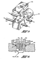
- Referring to Figure 1, the refrigerant flow control system of the present invention is indicated generally at 10 as having a compressor/
pump 12 which may be powered at any convenient manner as for example, an engine drivenbelt 14, and energized by a suitableelectrical clutch mechanism 15. The compressor discharges fluid through aconduit 16 connected to the inlet of a suitable exothermic heat exchanger orcondenser 18, which has the outlet thereof connected viaconduit 19 through a suitable receiver/dryer 22 andconduit 20 to the high pressure inlet port of an electrically operated valve indicated generally at 24. The valve is electrically operated preferably by asolenoid 26, with the outlet of the valve connected viaconduit 28 to the inlet port of an endothermic heat exchanger orevaporator 30. The outlet ofheat exchanger 30 is connected throughconduit 32 via a passage through thevalve 24 to the return or suction port of thecompressor 12. - The endothermic heat exchanger, or
evaporator 30, has attached thereto aplenum 34 which has therein asuitable blower 36 for forcing air across theevaporator 30 for discharge into the passenger compartment. - The
valve 24 has avalve block 40 which contains therein a valve seat and a movable valve member (not shown) for controlling flow throughconduit 20 to conduit 28. Valve 24 has a temperature sensor preferably in the form of a thermistor disposed through theblock 40, as indicated generally byreference number 42, for sensing directly the temperature of the refrigerant flowing on the downstream or expansion side of the valve to conduit 28. Thermistor 42 is connected schematically vialeads control signal generator 50; and, both are electrically energized by asuitable power supply 52 which may comprise the onboard vehicle power supply. - The
valve block 40 also has a temperature sensor in the form of a thermistor, indicated generally at 54, received therethrough which penetrates throughconduit 32 for directly sensing the temperature of the refrigerant flowing therein,thermistor 54 is shown schematically connected vialeads microprocessor 48. - Preferably, a third thermistor, indicated generally at 88, is employed as will hereinafter be described in greater detail.
- The valve operator or
solenoid 26 is powered by a control signal from thegenerator 50 supplied schematically along leads 60, 62. Themicrocomputer 48 also receives "Temperature Select" input commands from thecontrol 64 which may comprise an in-dash mounted touch-activated control or alternatively a dial or lever; and, thecontrol 64 provides input as shown schematically along leads 60, 68. - Referring to Figure 2, the details of the preferred manner of mounting and installing the
thermistors annular flange 70 seated in a flat bottom counter bore orrecess 72 provided in the wall of thevalve block 40. A pair of spacedelectrical terminals annular flange 70 and extend axially outwardly therefrom and are supported and sealed therein by suitable fused glass insulation indicated byreference numeral 80 in a manner well known in the art. Each of thethermistors reference numeral 78, attached to theleads - The annular flange is sealed by a suitable
elastomeric seal ring 82 provided between the flange and the block; and, the flange is retained in thebore 72 by deforming the material of the block about thebore 72 over the edge of the flange with a suitable tool indicated byreference numeral 84 in Figure 2. The annular flange having the terminals sealed therein is held in position during the deformation or staking operations by a suitableannular tool 86 which is urged axially downward as shown in Figure 2 to compress theseal ring 82 and hold theflange 70 against the shoulder or flat bottom ofcounter bore 72 while the block material is deformed over the edge of the flange. The thermistor mounting technique shown in Figure 2 thus eliminates the need for providing threads or separate fastening devices to retain and seal the thermistor in the block. - In the present practice of the invention the
thermistors reference numeral 78 in Fig. 2, in the form of a resistance having a negative temperature coefficient. One commercially available negative coefficient device which has been found to be satisfactory is obtainable from Fenwall Electronics Division of Kidde Corp. 63 Fountain Street, Framingham, Massachusetts 01701 and bearing manufacturer's type designation UUR43J24. It will be understood however, that other types of such devices may be used. - In operation, upon start-up the control valve is given an initial duty cycle by the microprocessor comprising a pulse of approximately 20 seconds which is about 70% of full pulse width to provide initial cooldown of the evaporator. In the present practice, it has been found satisfactory to provide an initial duty cycle of three (3) minutes where the temperature of the refrigerant at the evaporator inlet, as sensed by
thermistor 42, is higher than 28°C. Thereafter, the temperature readings ofthermistor compressor 12 has been set in the range of 5-10 seconds. - The change in pulse width or amplitude, where an amplitude modulated signal is employed, is thereafter modified in accordance with changes in the difference in the temperature readings of
thermistors thermistor 54 is higher than the temperature sensed bythermistor 42; and, Delta T is defined negative when the temperature sensed bythermistor 54 is lower than the temperature sensed bythermistor 42. The rate of change Delta Delta T is termed as positive when the temperature difference between the readings ofthermistors 
- The procedure for implementing the control strategy of table I is as follows:
measure T₄₂ evaporator inlet temperature;
measure T₅₄ evaporator outlet temperature;
calculate ΔT = T₅₄ - T₄₂;
calculate ΔΔT = ΔTnew - ΔTold;
determine whether ΔT is positive, negative or zero;
if ΔT is positive - step A below;
if ΔT is zero - step B below;
if ΔT is negative - step C below; - A. where ΔT is positive, determine whetherΔΔT is positive, negative or zero;
- (i) if ΔΔT is positive, add

- (ii) if ΔΔT is zero, add 1/2 ΔT to duty cycle;
- (iii) if ΔΔT is negative, subtract ΔΔT from duty cycle when ΔT < 3°C;
- (i) if ΔΔT is positive, add
- B. where ΔT is zero, add ΔΔT to duty cycle.
- C. where ΔT is negative, determine whether ΔΔT is positive, negative or zero;
- (i) if ΔΔT is positive, add ΔΔT to duty cycle when ΔT > -3°C;
- (ii) if ΔΔT is zero, subtract 1/2 ΔT from duty cycle;
- (iii)if ΔΔT is negative, subtract 1/2(ΔT × ΔΔT) from duty cycle;
- The control strategy set forth in Table I has been found satisfactory for an endothermic heat exchanger or evaporator operating with not more than 25 psi (1.75 Kg/cm²) fluid pressure drop thereacross, e.g. pressure differential between
conduit 28 andconduit 32. It will be understood that the control signal changes indicated in Table I are applied as a percentage to the steady state signal and are intended as applicable to either a pulse width modulated or an amplitude modulated control signal. - In the presently preferred practice, the temperature signal from
thermistor 42 may also be employed by thecomputer 48 to signal to the control signal generator for de-energizing thecompressor clutch 15 whenthermistor 42 senses refrigerant temperature below -6.7°C as an indication of low refrigerant pressure. - When the sensed temperature T₄₂ is at -5.5°C at time t=0, and at time t=5 minutes after compressor clutch "ON", T₄₂ is greater than -5.5°C, the
computer 48 signals controlsignal generator 50 to cut off thecompressor clutch 15 as an indication of low refrigerant charge. In the event T₄₂ is 5.5°C at time t=0 and T₄₂ is greater than 5.5°C at time t=1 minute after compressor clutch "ON", the compressor clutch is cycled "OFF" as an indication that the system is out of refrigerant charge. - For normal operational cycling of the
compressor clutch 15, when T₄₂, reaches 7.2°C which is a chosen predetermined value, the clutch is turned "ON"; and, when T₄₂ falls to -5.5°C which is a chosen predetermined value, the clutch is cycled "OFF". - It will further be understood that although the
temperature thermistors thermistors conduits evaporator 30. Thethermistors - Referring now to Figures 1 and 3, the third temperature sensor in the form of a
thermistor 88 is provided through the wall of thevalve block 40 in the manner shown for the typical sensor installation in Figure 2. Thethermistor 88 has its sensing element extending into the flow path through theinlet conduit 20 on the high pressure inlet side of the valve for sensing the temperature of the refrigerant from the condensor, viadryer 22, as it enters thevalve 24. Thethermistor 88 is connected, schematically via leads 90, 92 in Figure 1, to themicroprocessor 48. Themicroprocessor 48 provides control logic for thecontrol signal generator 50 which generates control signals schematically along leads 94, 96 to the electrically controlledcompressor clutch 15 and to the condensor cooling fan, indicated generally at 98, which is driven by amotor 100, shown in Figure 1 connected schematically to thecontrol signal generator 50 byleads thermistor 88 sensing a predetermined temperature of the refrigerant flow inconduit 20, a signal is provided to the microprocessor for energizing thefan 98 to cool thecondensor 18. Themicroprocessor 48, may also interpret the temperature signal fromsensor 88 as an indication that excessive pressure is present in thefluid conduit 20 and function to generate a signal fromcontrol signal generator 50, alongschematic lines compressor 12. In the present practice of the invention, when T₈₈ is greater than 90.5°C which is a chosen predetermined value, the compressor clutch is de-energized on the basis that an overpressure condition exists. Then T₈₈ reaches 72°C, thecomputer 98 signals controlgenerator 50 to energizecondensor fan motor 100; and, when T₈₈ drops to 68°C,fan motor 100 is de-energized. - Referring to Figure 3, the
valve 24 is shown in the preferred practice with an electronic controller module, indicated generally at 106, disposed for direct plug-in connection to the terminals of thethermistors power terminals valve solenoid coil 26. Thecontroller module 106 includes thepower supply 52, thecontrol signal generator 50 and themicroprocessor 48. Themodule 106 is thus heat-sinked by direct contact with thevalve block 40. -
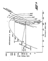
Connector terminals module 106 and are adapted for connection to the vehicle power source and appropriate temperature selection control inputs, as for example, from temperatureselect control 64 as shown in Figure 1. Terminal connections are also provided for signal outputs to thesolenoid 26 for thevalve 24, thecompressor clutch 15 and thefan motor 100. It will be understood that the two wire connections shown schematically in Figure 1 would be replaced by single wire leads in achassis ground 12 volt d.c. system such as that used on typical automotive applications. - Referring to Figure 5, an absolute pressure means enthalpy plot is illustrated for R-12 refrigerant with a family of isotherms cross-plotted and the familiar saturated vapor "dome" shown in solid line. A typical cycle for the refrigerant during operation of an automotive air conditioning system employing the present invention for control thereof, is illustrated by the solid line interconnecting the points A, B, C and D. It will be noted from the solid line plot in Figure 5, that for a maximum pressure differential across the evaporator of 25 psi, denoted by Delta Pmax, with saturated vapor at 40°F at the evaporator inlet, the system functions to maintain the temperature difference between
thermistor 42, denoted by the point B on the graph andthermistor 54, denoted by point C on the graph at a zero differential or constant temperature. If the point on the 40°F isotherm for superheated vapor at the evaporator outlet is located corresponding to Delta Pmax, it will be seen that the point falls to the right of the saturated vapor "dome" on the graph; and, thus for the range of pressure differentials experienced in evaporators of the type used for typical automotive air conditioning applications, only a minor amount of super heat is experienced by maintaining the temperature at the evaporator outlet (thermistor 54) at the same temperature as the evaporator inlet (thermistor 42). - The solid line interconnecting points C and D on the graph represents the essentially isentropic compression in the compressor; and, the solid line interconnecting points D and A represents the substantially constant pressure cooling in the
condensor 30. The solid line interconnecting point A and point B represents the substantially isenthalpic expansion which occurs by flow of the refrigerant through theexpansion valve 24. - The expansion valve outlet fluid pressure of 50 psi for point B and 200 psi for compressor output (line D-A) has been shown as typical for automotive passenger vehicle air conditioning systems. It will thus be seen from the plot in Figure 5 that the strategy of maintaining the temperature of the refrigerant discharged from the evaporator at the same temperature as the refrigerant entering the evaporator is a valid control strategy and will maintain the refrigerant discharging from the evaporator in a vapor state at only a slightly superheated condition, thereby insuring maximum utilization of the evaporator.
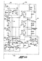
- Referring to Figure 4A and 4B, the electrical schematic for the control module is illustrated and is divided along the party line I-I for ease of illustration. The values of resistors and capacitors and identification of solid state components are given in Table II and have been omitted from the drawings for clarity.
- In Figure 4A, the components bounded by the dashed
outline 112 comprise a signal conditioning analog-to-digital converter for the input signals from thethermistors thermistor 42 atpins 8 and 11 and is connected to the oscillator atpins thermistor 88 is applied to themicroprocessor 48 atpins thermistor 54 is applied atpins microprocessor 48 comprises a commercially available device bearing a type designation 6805P3. - In operation, the microprocessor typically pulses through
pin 8, a timing device denoted 113, which preferably comprises a commerciallyavailable type 556 device, to commence charging of the capacity C₄. When the capacitor is charged to 2/3 Vcc or positive 5 Volts dc, the output ofdevice 113 is applied to pin 11 of themicroprocessor 48 for signalling the end of the time period. The microprocessor then compares the signals fromthermistor 42 with the signal fromthermistor 54 as recieved onpin 9. The microprocessor then outputs a signal to the predriver indiciative of the comparison. - The components bounded by the dashed
outline 118 in Figure 4B comprises a predriver circuit employing power FET's Q7, Q8 and Q9, which, in conjunction with the output driver circuit denoted by dashedoutline 120, comprise thecontrol signal generator 50. The output of device Q7 in theoutput driver circuit 120 is connected to thesolenoid 26; and, the output of FET driver Q8 is connected to thecompressor clutch 15. The output of driver FET Q9 is connected to thefan motor 100. - The circuit components enclosed in dashed
outline 116 in Figure 4A comprise a timer circuit which times out and resets themicroprocessor 48 unless the timer circuit is continually refreshed by the microprocessor from a pulse atpin 14 which occurs once each 70 millisecond during normal microprocessor operation, thereby permitting continued operation of the microprocessor only if operation is normal. In the event of a malfunction within the microprocessor, failure to provide a pulse atpin 14 will cause thecircuit 122 to time out and cut off the outputs of thepredriver circuit 122. - The circuit component within the dashed outline denoted by the
reference numeral 52 in figures 4A and 4B comprises a voltage regulating power supply circuit which provides a regulated positive five volts dc supply for the solid state components from the 12 volt dc onboard vehicle supply. - The circuit components bounded by dashed
outline 122 in Figures 4A and 4B comprises an over-current sensing circuit which employs a 22 AWG jumper wire resistor JP1 in circuit with the driver pins of FEG's Q7, Q8 and Q9. Thecircuit 122 senses the voltage drop across JP1; and, signals the microprocessor when an over-current condition is sensed and shuts down the output drivers Q7, Q8 and Q9. A more detailed description of the circuit of Figures 4A and 4B is omitted for simplicity; as, those skill in the art will be able to readily recongnize the technique employed as known.
- The present invention thus provides a unique and novel way of controlling refrigerant flow in a system for air conditioning in a compartment such as an automotive passenger compartment, and employs temperature sensors for sensing the temperature of the refrigerant entering and discharging from the endothermic heat exchanger or evaporator. The present invention provides electrical remote control of refrigerant flow and eliminates the need for sensing the pressure of the refrigerant in the flow lines. Although the invention has hereinabove been described with respect to the presently preferred practice, it will be understood that the invention is capable of modifications and variation and is limited only by the following claims.
Claims (20)
decreasing the duty cycle energization of said valve by not more than ten percent when said comparison is a negative two degrees Centigrade or more.
decreasing the duty cycle of energization of said valve by not more than five percent when said comparison indicates the difference in said temperature is negative and more than one , but not more than two degrees Centigrade; and, maintaining the duty cycle of energization of said valve substantially unchanged when said comparison of said temperatures indicates the difference is zero, positive or negative, but not more than one degree Centigrade.
sensing the temperature of refrigerant entering said endothermic heat exchanger at the beginning and end of a predetermined time interval and disabling said compressing when said sensed temperature at the end of said interval is above a predetermined level as an indication of low or insufficient refrigerant charge.
disabling said compressing when the sensed temperature of refrigerant entering said endothermic heat exchanger is above a predetermined level as an indicator of low refrigerant pressure.
Applications Claiming Priority (2)
| Application Number | Priority Date | Filing Date | Title |
|---|---|---|---|
| US714787A | 1987-01-27 | 1987-01-27 | |
| US7147 | 2001-11-12 |
Publications (3)
| Publication Number | Publication Date |
|---|---|
| EP0276491A2 true EP0276491A2 (en) | 1988-08-03 |
| EP0276491A3 EP0276491A3 (en) | 1988-12-28 |
| EP0276491B1 EP0276491B1 (en) | 1992-04-01 |
Family
ID=21724492
Family Applications (1)
| Application Number | Title | Priority Date | Filing Date |
|---|---|---|---|
| EP87119374A Expired - Lifetime EP0276491B1 (en) | 1987-01-27 | 1987-12-30 | Control system for air cooling |
Country Status (4)
| Country | Link |
|---|---|
| EP (1) | EP0276491B1 (en) |
| JP (1) | JPS63217167A (en) |
| KR (1) | KR880009246A (en) |
| DE (1) | DE3778003D1 (en) |
Cited By (7)
| Publication number | Priority date | Publication date | Assignee | Title |
|---|---|---|---|---|
| EP0539944A2 (en) * | 1991-10-31 | 1993-05-05 | Eaton Corporation | Expansion valve and temperature sensing assembly therefor |
| EP0678717A3 (en) * | 1990-01-31 | 1996-04-03 | Eaton Corp | Thermostatic expansion valve with electronic controller. |
| EP0726180A1 (en) * | 1995-02-08 | 1996-08-14 | Eaton Corporation | Controlling an electrically actuated refrigerant expansion valve |
| WO1998014739A1 (en) * | 1996-09-30 | 1998-04-09 | Parker-Hannifin Corporation | Mass flow control of a working fluid |
| WO2007130769A3 (en) * | 2006-03-31 | 2008-03-06 | Parker Hannifin Corp | Electronic block valve |
| WO2019057533A1 (en) | 2017-09-20 | 2019-03-28 | Basf Se | Method for producing a shaped catalyst body |
| EP3623673A4 (en) * | 2017-05-09 | 2021-01-06 | Zhejiang Sanhua Automotive Components Co., Ltd. | Electronic expansion valve, thermal management assembly, cooling system, and method for manufacturing electronic expansion valve |
Citations (11)
| Publication number | Priority date | Publication date | Assignee | Title |
|---|---|---|---|---|
| US3289429A (en) * | 1965-06-29 | 1966-12-06 | Westinghouse Electric Corp | Controls for refrigeration systems having air cooled condensers |
| US3537272A (en) * | 1968-08-22 | 1970-11-03 | Hall Thermotank Intern Ltd | Expansion valve control including plural sensors |
| FR2316558A1 (en) * | 1975-07-03 | 1977-01-28 | Fiat Spa | Refrigerant control valve for vehicle air conditioning system - has valve member controlled by external controls and thermodynamic refrigerant conditions |
| US4459819A (en) * | 1982-03-05 | 1984-07-17 | Emerson Electric Co. | Pulse controlled expansion valve and method |
| US4478051A (en) * | 1983-05-06 | 1984-10-23 | Tyler Refrigeration Corporation | Electronic temperature control system |
| US4506518A (en) * | 1981-06-17 | 1985-03-26 | Pacific Industrial Co. Ltd. | Cooling control system and expansion valve therefor |
| EP0147356A2 (en) * | 1983-12-22 | 1985-07-03 | Carrier Corporation | A control system for an electronic expansion valve in a refrigeration system |
| US4527399A (en) * | 1984-04-06 | 1985-07-09 | Carrier Corporation | High-low superheat protection for a refrigeration system compressor |
| FR2567985A1 (en) * | 1984-07-17 | 1986-01-24 | Singer Co | ELECTRICALLY ACTUATED RELIEF VALVE AND AIR CONDITIONING INSTALLATION FOR VEHICLES, IN PARTICULAR FOR MOTOR VEHICLES, PROVIDED WITH SUCH A VALVE |
| EP0171240A2 (en) * | 1984-08-08 | 1986-02-12 | Richard H. Alsenz | Closed vapor cycle refrigerator |
| GB2168467A (en) * | 1984-12-14 | 1986-06-18 | Sanden Corp | Refrigerating apparatus for an air conditioner and a refrigerator of a vehicle |
-
1987
- 1987-12-30 DE DE8787119374T patent/DE3778003D1/en not_active Expired - Lifetime
- 1987-12-30 EP EP87119374A patent/EP0276491B1/en not_active Expired - Lifetime
-
1988
- 1988-01-25 JP JP63014364A patent/JPS63217167A/en active Pending
- 1988-01-27 KR KR1019880000639A patent/KR880009246A/en not_active Application Discontinuation
Patent Citations (11)
| Publication number | Priority date | Publication date | Assignee | Title |
|---|---|---|---|---|
| US3289429A (en) * | 1965-06-29 | 1966-12-06 | Westinghouse Electric Corp | Controls for refrigeration systems having air cooled condensers |
| US3537272A (en) * | 1968-08-22 | 1970-11-03 | Hall Thermotank Intern Ltd | Expansion valve control including plural sensors |
| FR2316558A1 (en) * | 1975-07-03 | 1977-01-28 | Fiat Spa | Refrigerant control valve for vehicle air conditioning system - has valve member controlled by external controls and thermodynamic refrigerant conditions |
| US4506518A (en) * | 1981-06-17 | 1985-03-26 | Pacific Industrial Co. Ltd. | Cooling control system and expansion valve therefor |
| US4459819A (en) * | 1982-03-05 | 1984-07-17 | Emerson Electric Co. | Pulse controlled expansion valve and method |
| US4478051A (en) * | 1983-05-06 | 1984-10-23 | Tyler Refrigeration Corporation | Electronic temperature control system |
| EP0147356A2 (en) * | 1983-12-22 | 1985-07-03 | Carrier Corporation | A control system for an electronic expansion valve in a refrigeration system |
| US4527399A (en) * | 1984-04-06 | 1985-07-09 | Carrier Corporation | High-low superheat protection for a refrigeration system compressor |
| FR2567985A1 (en) * | 1984-07-17 | 1986-01-24 | Singer Co | ELECTRICALLY ACTUATED RELIEF VALVE AND AIR CONDITIONING INSTALLATION FOR VEHICLES, IN PARTICULAR FOR MOTOR VEHICLES, PROVIDED WITH SUCH A VALVE |
| EP0171240A2 (en) * | 1984-08-08 | 1986-02-12 | Richard H. Alsenz | Closed vapor cycle refrigerator |
| GB2168467A (en) * | 1984-12-14 | 1986-06-18 | Sanden Corp | Refrigerating apparatus for an air conditioner and a refrigerator of a vehicle |
Cited By (11)
| Publication number | Priority date | Publication date | Assignee | Title |
|---|---|---|---|---|
| EP0678717A3 (en) * | 1990-01-31 | 1996-04-03 | Eaton Corp | Thermostatic expansion valve with electronic controller. |
| EP0539944A2 (en) * | 1991-10-31 | 1993-05-05 | Eaton Corporation | Expansion valve and temperature sensing assembly therefor |
| EP0539944A3 (en) * | 1991-10-31 | 1993-08-04 | Eaton Corporation | Expansion valve and temperature sensing assembly therefor |
| EP0726180A1 (en) * | 1995-02-08 | 1996-08-14 | Eaton Corporation | Controlling an electrically actuated refrigerant expansion valve |
| WO1998014739A1 (en) * | 1996-09-30 | 1998-04-09 | Parker-Hannifin Corporation | Mass flow control of a working fluid |
| US5877476A (en) * | 1996-09-30 | 1999-03-02 | Parker-Hannifin Corp. | Apparatus and method for mass flow control of a working fluid |
| WO2007130769A3 (en) * | 2006-03-31 | 2008-03-06 | Parker Hannifin Corp | Electronic block valve |
| US8281607B2 (en) | 2006-03-31 | 2012-10-09 | Parker-Hannifin Corporation | Electronic block valve |
| EP3623673A4 (en) * | 2017-05-09 | 2021-01-06 | Zhejiang Sanhua Automotive Components Co., Ltd. | Electronic expansion valve, thermal management assembly, cooling system, and method for manufacturing electronic expansion valve |
| US11698146B2 (en) | 2017-05-09 | 2023-07-11 | Zhejiang Sanhua Automotive Components Co., Ltd. | Electronic expansion valve, thermal management assembly, cooling system, and method for manufacturing electronic expansion valve |
| WO2019057533A1 (en) | 2017-09-20 | 2019-03-28 | Basf Se | Method for producing a shaped catalyst body |
Also Published As
| Publication number | Publication date |
|---|---|
| DE3778003D1 (en) | 1992-05-07 |
| JPS63217167A (en) | 1988-09-09 |
| EP0276491B1 (en) | 1992-04-01 |
| EP0276491A3 (en) | 1988-12-28 |
| KR880009246A (en) | 1988-09-14 |
Similar Documents
| Publication | Publication Date | Title |
|---|---|---|
| US4848100A (en) | Controlling refrigeration | |
| US4995240A (en) | Controlling refrigeration having control module directly attached on valve body | |
| US4835976A (en) | Controlling superheat in a refrigeration system | |
| US4132086A (en) | Temperature control system for refrigeration apparatus | |
| US5289692A (en) | Apparatus and method for mass flow control of a working fluid | |
| US4794762A (en) | Refrigerant flow control system | |
| US5481884A (en) | Apparatus and method for providing low refrigerant charge detection | |
| EP0315780B1 (en) | Indicating refrigerant liquid saturation point | |
| US5477701A (en) | Apparatus and method for mass flow control of a working fluid | |
| US6460354B2 (en) | Method and apparatus for detecting low refrigerant charge | |
| US5197298A (en) | Sensor and control system for an automotive air conditioning system | |
| WO1994017346A9 (en) | System for controlling flow of working fluids | |
| EP0276491A2 (en) | Control system for air cooling | |
| US4785639A (en) | Cooling system for operation in low temperature environments | |
| US5877476A (en) | Apparatus and method for mass flow control of a working fluid | |
| US5660052A (en) | Apparatus and method for detecting characteristics of a working fluid | |
| EP0557747B1 (en) | Measuring evaporator load in an automotive air conditioning system for compressor clutch control | |
| US5335513A (en) | Apparatus and method for detecting characteristics of a working fluid | |
| JPH0565779B2 (en) | ||
| US5216892A (en) | Compressor clutch cut-out control in an automotive air conditioning system | |
| EP0085245B1 (en) | A capacity control device for a compressor in a refrigerating system | |
| JPS62182563A (en) | Refrigeration cycle device | |
| JPS63135761A (en) | Refrigeration cycle device | |
| JPS6115061A (en) | Refrigerator for car | |
| JPS62261521A (en) | Refrigerating cycle device |
Legal Events
| Date | Code | Title | Description |
|---|---|---|---|
| PUAI | Public reference made under article 153(3) epc to a published international application that has entered the european phase |
Free format text: ORIGINAL CODE: 0009012 |
|
| AK | Designated contracting states |
Kind code of ref document: A2 Designated state(s): DE FR GB |
|
| PUAL | Search report despatched |
Free format text: ORIGINAL CODE: 0009013 |
|
| AK | Designated contracting states |
Kind code of ref document: A3 Designated state(s): DE FR GB |
|
| 17P | Request for examination filed |
Effective date: 19890615 |
|
| 17Q | First examination report despatched |
Effective date: 19900314 |
|
| GRAA | (expected) grant |
Free format text: ORIGINAL CODE: 0009210 |
|
| AK | Designated contracting states |
Kind code of ref document: B1 Designated state(s): DE FR GB |
|
| REF | Corresponds to: |
Ref document number: 3778003 Country of ref document: DE Date of ref document: 19920507 |
|
| ET | Fr: translation filed | ||
| PLBE | No opposition filed within time limit |
Free format text: ORIGINAL CODE: 0009261 |
|
| STAA | Information on the status of an ep patent application or granted ep patent |
Free format text: STATUS: NO OPPOSITION FILED WITHIN TIME LIMIT |
|
| 26N | No opposition filed | ||
| REG | Reference to a national code |
Ref country code: GB Ref legal event code: IF02 |
|
| PGFP | Annual fee paid to national office [announced via postgrant information from national office to epo] |
Ref country code: GB Payment date: 20021104 Year of fee payment: 16 |
|
| PGFP | Annual fee paid to national office [announced via postgrant information from national office to epo] |
Ref country code: FR Payment date: 20021202 Year of fee payment: 16 |
|
| PGFP | Annual fee paid to national office [announced via postgrant information from national office to epo] |
Ref country code: DE Payment date: 20021230 Year of fee payment: 16 |
|
| PG25 | Lapsed in a contracting state [announced via postgrant information from national office to epo] |
Ref country code: GB Free format text: LAPSE BECAUSE OF NON-PAYMENT OF DUE FEES Effective date: 20031230 |
|
| PG25 | Lapsed in a contracting state [announced via postgrant information from national office to epo] |
Ref country code: DE Free format text: LAPSE BECAUSE OF NON-PAYMENT OF DUE FEES Effective date: 20040701 |
|
| GBPC | Gb: european patent ceased through non-payment of renewal fee |
Effective date: 20031230 |
|
| PG25 | Lapsed in a contracting state [announced via postgrant information from national office to epo] |
Ref country code: FR Free format text: LAPSE BECAUSE OF NON-PAYMENT OF DUE FEES Effective date: 20040831 |
|
| REG | Reference to a national code |
Ref country code: FR Ref legal event code: ST |