EP0273848A2 - Engine control with smooth transition to synthesized parameter - Google Patents
Engine control with smooth transition to synthesized parameter Download PDFInfo
- Publication number
- EP0273848A2 EP0273848A2 EP87630241A EP87630241A EP0273848A2 EP 0273848 A2 EP0273848 A2 EP 0273848A2 EP 87630241 A EP87630241 A EP 87630241A EP 87630241 A EP87630241 A EP 87630241A EP 0273848 A2 EP0273848 A2 EP 0273848A2
- Authority
- EP
- European Patent Office
- Prior art keywords
- parameter
- value
- engine
- synthesized
- signal
- Prior art date
- Legal status (The legal status is an assumption and is not a legal conclusion. Google has not performed a legal analysis and makes no representation as to the accuracy of the status listed.)
- Granted
Links
- 230000007704 transition Effects 0.000 title 1
- 238000000034 method Methods 0.000 claims description 5
- 230000001105 regulatory effect Effects 0.000 claims 1
- 239000000446 fuel Substances 0.000 description 15
- 230000000694 effects Effects 0.000 description 3
- 230000001052 transient effect Effects 0.000 description 3
- 238000010586 diagram Methods 0.000 description 2
- 230000001133 acceleration Effects 0.000 description 1
- 238000005516 engineering process Methods 0.000 description 1
- 239000007921 spray Substances 0.000 description 1
Images
Classifications
-
- F—MECHANICAL ENGINEERING; LIGHTING; HEATING; WEAPONS; BLASTING
- F02—COMBUSTION ENGINES; HOT-GAS OR COMBUSTION-PRODUCT ENGINE PLANTS
- F02C—GAS-TURBINE PLANTS; AIR INTAKES FOR JET-PROPULSION PLANTS; CONTROLLING FUEL SUPPLY IN AIR-BREATHING JET-PROPULSION PLANTS
- F02C9/00—Controlling gas-turbine plants; Controlling fuel supply in air- breathing jet-propulsion plants
- F02C9/26—Control of fuel supply
- F02C9/28—Regulating systems responsive to plant or ambient parameters, e.g. temperature, pressure, rotor speed
Definitions
- This invention relates to engine controls for gas turbine engines.
- Fuel controls for gas turbine engines operate in a closed loop fashion based on an engine parameter, such as engine pressure ratio (EPR) which is the ratio of the engine exhaust to engine inlet total pressure P5/P2.
- EPR engine pressure ratio
- a desired or reference EPR is computed based upon throttle setting and prevailing atmospheric conditions and is compared to the actual EPR of the engine; fuel is modulated to drive the resultant error term to zero.
- a detected failure of any one of the signals necessary to compute either the reference EPR or the actual EPR forces operation of the control based upon an alternate control mode, such as the speed N1 of the low compressor if the engine is a twin spool gas turbine engine. In that case, a reference N1 (N 1ref ) is computed based upon prevailing conditions and throttle setting.
- Bumps at a minimum, can be unsettling to the pilot and passengers of the aircraft. Furthermore, if they occur during transient engine operation they can be dangerous, such as when the pilot suddenly calls for full power, and the engine does not respond in the manner expected.
- One object of the present invention is an engine control for a gas turbine engine which can transfer from operation based upon a first engine parameter to operation based on a different engine parameter with minimum effect on engine operation at the time of switchover.
- Another object of the present invention is a fuel control for a gas turbine engine which switches from operating as a function of the actual value of one parameter to operating as a function of a synthesized value of that parameter with minimal effect on engine operation at the time of switchover.
- a gas turbine engine control system which regulates the engine as a function of the actual value of one parameter and switches to operating as a function of a synthesized value of that parameter upon loss of a reliable actual value, using, as the initial synthesized value of the parameter at the time of switchover, the actual value of the parameter last measured before loss, and thereafter incrementally changing that initial value by the same amount the synthesized value of the parameter changes.
- this invention Upon loss of the actual value of the parameter, and thereafter, this invention effectively applies a constant value trim to the synthesized value of the parameter.
- the magnitude of the trim is an amount which makes the synthesized value at the instant of switchover equal to the last good measured value of the parameter.
- the synthesized parameter is compressor speed, but the present invention may be used to eliminate bumps in engine operation caused by switching from actual to synthesized values of any parameter.
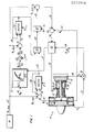
- twin spool turbofan gas turbine engine shown in the drawing and generally represented by the reference numeral 10.
- the engine comprises a low compressor 12 connected through a shaft to a low turbine 14; a high compressor 16 connected through a shaft to a high turbine 18; and a burner section 20 disposed between the high compressor and the high turbine.
- a plurality of fuel nozzles 22 spray fuel into the burners 24 of the burner section 20. Fuel flow rate into the nozzles 22 is varied by a valve 26.
- An electronic engine control automatically regulates engine operation, such as fuel flow rate, based upon pilot demand (throttle setting), various aircraft and engine parameters and scientific and empirically developed relationships between various parameters.
- the electronic engine control's primary mode of fuel flow control is based upon engine total pressure ratio (EPR), which is the ratio of the engine outlet pressure (P5) to the engine inlet pressure (P2).
- EPR engine total pressure ratio
- P5 the ratio of the engine outlet pressure
- P2 the engine inlet pressure
- a signal 28 indicative of the inlet pressure and a signal 30 indicative of the outlet pressure are delivered to a divider 32.
- the output signal 34 from the divider is the engine pressure ratio, which signal is delivered to a portion of the fuel control designated by the box 36.
- Within the control portion 36 is a schedule of engine pressure ratios against which the actual pressure ratio is compared.
- the control portion 36 sends a signal 38 to the fuel nozzle valve 26 to adjust the fuel flow, and thereby the engine speed, until the actual engine pressure ratio matches the scheduled engine pressure ratio for the
- the control portion 36 switches to a secondary parameter, low compressor speed N1, to control the fuel flow.
- a control portion 40 continuously produces an output signal 42 indicative of a scheduled low compressor reference speed N 1ref .
- This reference speed is the maximum speed that the engine can tolerate under existing conditions and throttle setting.
- a signal 44 indicative of the actual low compressor speed N1 is subtracted from N 1ref in a subtractor 46; and a signal 48 indicative of that difference is delivered to a switch 50.
- N1 will be a value which is a function of EPR in accordance with the EPR schedule built into the control.
- a signal 52 is delivered to the switch 50 when an EPR mode failure occurs.
- the output 53 of the switch 50 is the presently calculated value of the signal 48, which is sent to a select-low gate 54.
- the switch 50 receives the signal 52, its output 53 is a signal 56 which is indicative of the value of the signal 48 last calculated prior to the switch receiving the signal 52; and that value of the signal 48 is thereafter continuously delivered to the select low gate 54.
- a function generator 58 continuously receives a signal 60 indicative of the aircraft Mach number M n and a signal 61 from the control portion 36 indicative of the scheduled engine pressure ratio. Based upon these inputs the function generator 58 generates a signal 62 (N E C2) indicative of the low compressor speed corrected to the temperature at the low compressor inlet. In a manner well known in the art, the corrected low compressor speed 62 and an appropriate multiplier 64 (a function of temperature at the low compressor inlet) are delivered into a multiplier 66 to yield a signal 68 indicative of an estimated value of the low rotor speed (N E ). The estimated low rotor speed signal 68 is subtracted from N 1ref in a subtractor 70 and a signal 72 indicative of that difference is delivered to a switch 74.
- a signal 76 is delivered to a switch 74 when an EPR mode failure occurs. When there is no signal 76 the switch 74 passes the presently calculated value of the signal 72. Upon receiving the signal 76 the output 78 of the switch 74 has the value of a signal 80 which is indicative of the value of the signal 72 last calculated prior to the switch 74 receiving the signal 76.
- the value of the signal 78 therefore represents the difference between N 1ref and an estimated low rotor speed based upon an engine pressure ratio schedule and the current engine throttle setting, and not based upon the current low rotor speed N1.
- the signal 68 which is the estimated compressor speed N E
- the speed signal 44 will be the actual engine speed at the time of EPR mode failure, which may be considerably different from the desired speed based upon the throttle setting and the EPR schedule.
- the speed difference signals 78 and 53 are both fed to the select-low gate 54, and the lower of the two signals, represented by the output signal 82, is passed to a select-high gate 84.
- the high gate 84 receives the signal 82 as well as a signal 86.
- the signal 86 is always zero. Thus, if the signal 82 is negative, the output signal 88 from the high gate 84 will be zero; otherwise it will be identical to the signal 82.
- the high gate 84 is used to assure that the value of the signal 88 (the N 1ref trim) is never negative, which could happen when the EPR mode failure occurs during a deceleration.
- a negative value for the signal 88 would result in a value of the signal 92 which is higher than N 1ref , which cannot be allowed since N 1ref is the maximum low compressor speed which the engine can safely tolerate. Thus, only a down-trim is applied to N 1ref .
- the value of the signal 88 is subtracted from N 1ref in a subtractor 90, and a signal 92 indicative of the difference is delivered to a subtractor 94 along with the current actual engine low compressor speed signal 44.
- An error signal 96 indicative of the difference between the actual engine speed N1 and the desired engine speed represented by the signal 92 is delivered into the control portion 36.
- the control portion 36 controls the fuel flow via the valve 26 to reduce the error signal 96 to zero.
- the primary parameter in this embodiment is the engine pressure ratio
- a primary parameter other than EPR e.g. fan pressure ratio or a weighted fan/engine pressure ratio
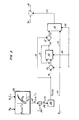
- N 1syn a synthesized value of N1 (hereinafter referred to as N 1syn ) to be used in the event of unavailability or unreliability of an actual measured value of N1.
- Fig. 2 shows a technique for eliminating such a bump.
- the parameter which is synthesized is N1.
- the parameter which is synthesized is N1.
- a synthesized value of N1 is continuously calculated from the most recent, valid information such that it is always up to date and ready for use upon the actual value of N1 becoming unavailable or unreliable (i.e., N1 failure).
- aircraft Mach number and the high compressor speed corrected to the temperature at the low compressor inlet (N2C2) are input to a function generator 200.
- the function generator 200 produces an output 202 which is an estimated value of the low compressor speed corrected to the temperature at the low compressor inlet (N 1syn C2).
- the value of the signal 202 is based upon empirically derived relationships between Mach number and corrected high compressor speed which, in turn, are based upon steady state engine characteristics.
- the corrected, estimated low compressor speed 202 and an appropriate multiplier 204 (which would be the same as the multiplier 64 of Fig. 1) are delivered into a multiplier 205 to yield a signal 206 indicative of an estimated or synthesized value of the low rotor speed (N 1syn ). Since the value of N 1syn is based upon empirical relationships between the high and low rotor during steady state engine operation, the signal 206 is passed through a compensator 208 which replaces the dynamic characteristics of the corrected high rotor speed N2C2 with that of the output N 1syn C2 during transient operation. During steady state operation the compensator will have no effect. Compensators of this nature are well known in the art.
- the N 1syn output signal 99 from the compensator 208, along with the signal 44 indicative of the actual measured value of N1 are continuously fed to a subtractor 100.
- a signal 102 representing the difference between them is fed to a switch 104, along with a signal 106 indicating whether or not N1 has failed (i.e. is unavailable or unreliable).
- the output 108 of the switch 104 will simply be the current calculated difference between N1 and N 1syn . If the signal 106 indicates N1 is not good, the output 108 will be the value of the signal 110, which is the last value of the difference between N1 and N 1syn calculated before the failure signal was received by the switch. In either event, the switch output 108 is sent to a subtractor 112, along with the N 1syn signal 99, and the output signal 114 therefrom is sent to another switch 116, along with a signal 44 indicative of the actual measured value of N1.
- the fault signal 106 is delivered to the switch 116. If the signal 106 indicates N1 is still good, then the N1 signal 44 is passed therethrough as the switch output signal 118. If N1 is bad, the signal 118 will have the value of the signal 114, which is an estimated value of N1. In a preferred embodiment the signal 118 replaces the signal 44 delivered to the subtractor 94 of Fig. 1.
Landscapes
- Engineering & Computer Science (AREA)
- Chemical & Material Sciences (AREA)
- Combustion & Propulsion (AREA)
- Mechanical Engineering (AREA)
- General Engineering & Computer Science (AREA)
- Feedback Control In General (AREA)
- Control Of Positive-Displacement Air Blowers (AREA)
- Control Of Turbines (AREA)
- Electrical Control Of Air Or Fuel Supplied To Internal-Combustion Engine (AREA)
Abstract
Description
- This invention relates to engine controls for gas turbine engines.
- Fuel controls for gas turbine engines operate in a closed loop fashion based on an engine parameter, such as engine pressure ratio (EPR) which is the ratio of the engine exhaust to engine inlet total pressure P₅/P₂. A desired or reference EPR is computed based upon throttle setting and prevailing atmospheric conditions and is compared to the actual EPR of the engine; fuel is modulated to drive the resultant error term to zero. A detected failure of any one of the signals necessary to compute either the reference EPR or the actual EPR forces operation of the control based upon an alternate control mode, such as the speed N₁ of the low compressor if the engine is a twin spool gas turbine engine. In that case, a reference N₁ (N1ref) is computed based upon prevailing conditions and throttle setting. This is compared to the actual N₁ and fuel is modulated to drive the resultant error term to zero. Because the characteristics of these different references are different, there could be a sudden change in engine speed at the time of transfer. This is sometimes referred to as a "bump". Bumps, at a minimum, can be unsettling to the pilot and passengers of the aircraft. Furthermore, if they occur during transient engine operation they can be dangerous, such as when the pilot suddenly calls for full power, and the engine does not respond in the manner expected.
- In the PW2037 twin spool engine manufactured by the Pratt & Whitney Division of United Technologies Corporation, it is known to eliminate bumps when a control mode change occurs by attempting to force the new reference parameter to match the failed reference parameter at the instant of failure. More specifically, if EPR is the primary mode and N₁ is the backup mode, it is known to continuously monitor N₁ during EPR operation and to use the last value thereof prior to EPR failure to trim the reference speed schedule such that N1ref (trimmed) equals the last measured value of N₁ at the instant of EPR failure. If the desired N₁ just after EPR failure (i.e. trimmed N1ref) is almost the same as N₁ just before the failure, the bump is virtually eliminated. This will be the case when EPR fails during steady state engine operation or at low rates of acceleration or deceleration; however, if EPR failure occurs near the onset of a significant engine transient the bump will not be eliminated as a result of the great difference between the engine speed at the time of EPR failure and the desired engine speed (N1ref) based upon the new throttle setting at the time of EPR failure. The fault logic will therefore overcompensate and the result may be a severe loss of engine thrust.
- One object of the present invention is an engine control for a gas turbine engine which can transfer from operation based upon a first engine parameter to operation based on a different engine parameter with minimum effect on engine operation at the time of switchover.
- Another object of the present invention is a fuel control for a gas turbine engine which switches from operating as a function of the actual value of one parameter to operating as a function of a synthesized value of that parameter with minimal effect on engine operation at the time of switchover.
- According to the present invention, in a gas turbine engine control system which regulates the engine as a function of the actual value of one parameter and switches to operating as a function of a synthesized value of that parameter upon loss of a reliable actual value, using, as the initial synthesized value of the parameter at the time of switchover, the actual value of the parameter last measured before loss, and thereafter incrementally changing that initial value by the same amount the synthesized value of the parameter changes.
- Upon loss of the actual value of the parameter, and thereafter, this invention effectively applies a constant value trim to the synthesized value of the parameter. The magnitude of the trim is an amount which makes the synthesized value at the instant of switchover equal to the last good measured value of the parameter. Thus, at the instant of switchover, although the control input suddenly becomes a synthesized value of the parameter, the value of that input is unchanged from the last measured value of the parameter, and the engine will not experience any sudden change or "bump" in its operation.
- In a preferred embodiment the synthesized parameter is compressor speed, but the present invention may be used to eliminate bumps in engine operation caused by switching from actual to synthesized values of any parameter.
- The foregoing and other objects, features and advantages of the present invention will become more apparent in the light of the following detailed description of preferred embodiments thereof as illustrated in the accompanying drawing.
-
- Fig. 1 is a schematic and block diagram of a twin spool gas turbine engine incorporating the control system of the present invention.
- Fig. 2 is a schematic and block diagram showing another aspect of the control system of the present invention.
- As an exemplary embodiment of the present invention, consider the twin spool turbofan gas turbine engine shown in the drawing and generally represented by the
reference numeral 10. The engine comprises alow compressor 12 connected through a shaft to alow turbine 14; ahigh compressor 16 connected through a shaft to ahigh turbine 18; and a burner section 20 disposed between the high compressor and the high turbine. A plurality offuel nozzles 22 spray fuel into theburners 24 of the burner section 20. Fuel flow rate into thenozzles 22 is varied by avalve 26. - An electronic engine control automatically regulates engine operation, such as fuel flow rate, based upon pilot demand (throttle setting), various aircraft and engine parameters and scientific and empirically developed relationships between various parameters. In this embodiment the electronic engine control's primary mode of fuel flow control is based upon engine total pressure ratio (EPR), which is the ratio of the engine outlet pressure (P₅) to the engine inlet pressure (P₂). As shown in the drawing, a
signal 28 indicative of the inlet pressure and asignal 30 indicative of the outlet pressure are delivered to adivider 32. Theoutput signal 34 from the divider is the engine pressure ratio, which signal is delivered to a portion of the fuel control designated by the box 36. Within the control portion 36 is a schedule of engine pressure ratios against which the actual pressure ratio is compared. The control portion 36 sends asignal 38 to thefuel nozzle valve 26 to adjust the fuel flow, and thereby the engine speed, until the actual engine pressure ratio matches the scheduled engine pressure ratio for the particular throttle setting. - If either the primary fuel control parameter, engine pressure ratio, or the engine pressure ratio schedules become unavailable or unreliable (hereinafter either occurrence is referred to as an EPR mode failure), the control portion 36 switches to a secondary parameter, low compressor speed N₁, to control the fuel flow. With reference to the drawing, a
control portion 40 continuously produces an output signal 42 indicative of a scheduled low compressor reference speed N1ref. This reference speed is the maximum speed that the engine can tolerate under existing conditions and throttle setting. Asignal 44 indicative of the actual low compressor speed N₁ is subtracted from N1ref in asubtractor 46; and asignal 48 indicative of that difference is delivered to aswitch 50. Of course, while the engine is still being controlled based upon EPR, N₁ will be a value which is a function of EPR in accordance with the EPR schedule built into the control. - A signal 52 is delivered to the
switch 50 when an EPR mode failure occurs. When no signal 52 is present theoutput 53 of theswitch 50 is the presently calculated value of thesignal 48, which is sent to a select-low gate 54. When theswitch 50 receives the signal 52, itsoutput 53 is asignal 56 which is indicative of the value of thesignal 48 last calculated prior to the switch receiving the signal 52; and that value of thesignal 48 is thereafter continuously delivered to the selectlow gate 54. - A
function generator 58 continuously receives a signal 60 indicative of the aircraft Mach number Mn and a signal 61 from the control portion 36 indicative of the scheduled engine pressure ratio. Based upon these inputs thefunction generator 58 generates a signal 62 (NEC₂) indicative of the low compressor speed corrected to the temperature at the low compressor inlet. In a manner well known in the art, the corrected low compressor speed 62 and an appropriate multiplier 64 (a function of temperature at the low compressor inlet) are delivered into amultiplier 66 to yield a signal 68 indicative of an estimated value of the low rotor speed (NE). The estimated low rotor speed signal 68 is subtracted from N1ref in asubtractor 70 and a signal 72 indicative of that difference is delivered to aswitch 74. - A
signal 76 is delivered to aswitch 74 when an EPR mode failure occurs. When there is nosignal 76 theswitch 74 passes the presently calculated value of the signal 72. Upon receiving thesignal 76 theoutput 78 of theswitch 74 has the value of asignal 80 which is indicative of the value of the signal 72 last calculated prior to theswitch 74 receiving thesignal 76. The value of thesignal 78 therefore represents the difference between N1ref and an estimated low rotor speed based upon an engine pressure ratio schedule and the current engine throttle setting, and not based upon the current low rotor speed N₁. Thus, if the engine pressure ratio or engine pressure ratio schedules become unavailable or unreliable immediately after the throttle has been moved and before the engine has had an opportunity to change from its old speed to its new speed, the signal 68, which is the estimated compressor speed NE, will be approximately the speed normally called for by the engine pressure ratio schedule at the new throttle setting. In contrast, thespeed signal 44 will be the actual engine speed at the time of EPR mode failure, which may be considerably different from the desired speed based upon the throttle setting and the EPR schedule. - The speed difference signals 78 and 53 are both fed to the select-
low gate 54, and the lower of the two signals, represented by theoutput signal 82, is passed to a select-high gate 84. Thehigh gate 84 receives thesignal 82 as well as asignal 86. Thesignal 86 is always zero. Thus, if thesignal 82 is negative, the output signal 88 from thehigh gate 84 will be zero; otherwise it will be identical to thesignal 82. Thehigh gate 84 is used to assure that the value of the signal 88 (the N1ref trim) is never negative, which could happen when the EPR mode failure occurs during a deceleration. A negative value for the signal 88 would result in a value of thesignal 92 which is higher than N1ref, which cannot be allowed since N1ref is the maximum low compressor speed which the engine can safely tolerate. Thus, only a down-trim is applied to N1ref. - The value of the signal 88 is subtracted from N1ref in a
subtractor 90, and asignal 92 indicative of the difference is delivered to a subtractor 94 along with the current actual engine lowcompressor speed signal 44. Anerror signal 96 indicative of the difference between the actual engine speed N₁ and the desired engine speed represented by thesignal 92 is delivered into the control portion 36. When either the enginepressure ratio signal 34 or the EPR schedules within the control portion 36 is unavailable or unreliable the control portion 36 controls the fuel flow via thevalve 26 to reduce theerror signal 96 to zero. - To avoid a "bump" during steady state it is necessary that the trim limiting mechanism of the control system not influence the trim operation when EPR mode failure occurs during steady state engine operation. This will be assured if the value of the signal 68 is always less than the value of the comrpessor speed which would have been called for by the throttle setting in the EPR mode. The Mach number curves used in the
function generator 58 are therefor selected to assure that NE will never be greater than and will preferably be slightly less than the speed called for by the EPR schedule at the time of EPR failure. - Although the primary parameter in this embodiment is the engine pressure ratio, it is apparent the present invention may be used with a primary parameter other than EPR (e.g. fan pressure ratio or a weighted fan/engine pressure ratio).
- In the event of failure of certain parameters required by a control system to operate an engine it is known to calculate a synthesized value of the failed parameter to be used in place of the actual measured parameter. For example, burner pressure is synthesized in commonly owned U.S. patent 4,212,161 to David M. Newirth et al. In the present control system it is desireable to calculate a synthesized value of N₁ (hereinafter referred to as N1syn) to be used in the event of unavailability or unreliability of an actual measured value of N₁.
- As with the sudden switchover to a different control mode, the switch from an actual to a synthesized parameter can result in a "bump". The control logic of Fig. 2 shows a technique for eliminating such a bump. In Fig. 2 the parameter which is synthesized is N₁. In the embodiment of Fig. 2 the parameter which is synthesized is N₁. A synthesized value of N₁ is continuously calculated from the most recent, valid information such that it is always up to date and ready for use upon the actual value of N₁ becoming unavailable or unreliable (i.e., N₁ failure). Referring to the drawing, aircraft Mach number and the high compressor speed corrected to the temperature at the low compressor inlet (N₂C₂) are input to a
function generator 200. Thefunction generator 200 produces anoutput 202 which is an estimated value of the low compressor speed corrected to the temperature at the low compressor inlet (N1synC₂). The value of thesignal 202 is based upon empirically derived relationships between Mach number and corrected high compressor speed which, in turn, are based upon steady state engine characteristics. - In a manner well known in the art, the corrected, estimated
low compressor speed 202 and an appropriate multiplier 204 (which would be the same as themultiplier 64 of Fig. 1) are delivered into a multiplier 205 to yield asignal 206 indicative of an estimated or synthesized value of the low rotor speed (N1syn). Since the value of N1syn is based upon empirical relationships between the high and low rotor during steady state engine operation, thesignal 206 is passed through acompensator 208 which replaces the dynamic characteristics of the corrected high rotor speed N₂C₂ with that of the output N1synC₂ during transient operation. During steady state operation the compensator will have no effect. Compensators of this nature are well known in the art. - The N1syn output signal 99 from the
compensator 208, along with thesignal 44 indicative of the actual measured value of N₁ are continuously fed to a subtractor 100. A signal 102 representing the difference between them is fed to aswitch 104, along with asignal 106 indicating whether or not N₁ has failed (i.e. is unavailable or unreliable). - If the
signal 106 indicates N₁ is good, the output 108 of theswitch 104 will simply be the current calculated difference between N₁ and N1syn. If thesignal 106 indicates N₁ is not good, the output 108 will be the value of thesignal 110, which is the last value of the difference between N₁ and N1syn calculated before the failure signal was received by the switch. In either event, the switch output 108 is sent to asubtractor 112, along with the N1syn signal 99, and the output signal 114 therefrom is sent to anotherswitch 116, along with asignal 44 indicative of the actual measured value of N₁. - The
fault signal 106 is delivered to theswitch 116. If thesignal 106 indicates N₁ is still good, then theN₁ signal 44 is passed therethrough as the switch output signal 118. If N₁ is bad, the signal 118 will have the value of the signal 114, which is an estimated value of N₁. In a preferred embodiment the signal 118 replaces thesignal 44 delivered to the subtractor 94 of Fig. 1. - In accordance with the present invention, it can be seen that at the instant of N₁ failure (i.e. upon switchover to the use of N1syn) the value of the output 114, and thus the value of the signal 118, will be the last good value of N₁ measured essentially at the instant before failure. Thereafter, the value of output 114 will increase and decrease incrementally by an amount equal to the change in the calculated value of N1syn. Thus, the control produces no bump at the instant of switchover and continues to control the engine smoothly as a function of N1syn.
- It should be apparent that the foregoing method for eliminating a bump upon switchover from actual engine speed to synthesized engine speed may be used to eliminate a bump in switching from the use of any measured parameter to the use of a synthesized value of that parameter.
- Additionally, it should be understood by those skilled in the art that other various changes and omissions in the form and detail of the invention may be made without departing from the spirit and scope thereof.
Claims (5)
continuously calculating a trim value as the difference between the synthesized and actual value of the first parameter;
upon loss of the actual value of the first parameter, fixing the value of the trim at the value last calculated before loss;
applying the fixed trim value to the synthesized value of the first parameter continuously after loss of the actual value of the first parameter; and
using, after loss of the actual value of the first parameter, the trimmed synthesized value of the first parameter in place of the actual value of the first parameter.
means for continuously calculating a trim value as the difference between the synthesized and actual value of the first parameter;
means for generating a failure signal when the actual value of the first parameter cannot be reliably determined;
means for receiving the failure signal and for fixing the value of the trim at the value last calculated by said trim calculating means prior to receiving the failure signal;
means for applying the fixed trim value to the synthesized value of the first parameter continuously after receiving the failure signal; and
means for using the trimmed synthesized value of the first parameter in place of the actual value of the first parameter to regulate the engine after receiving the failure signal.
Applications Claiming Priority (2)
| Application Number | Priority Date | Filing Date | Title |
|---|---|---|---|
| US06/939,215 US4773213A (en) | 1986-12-08 | 1986-12-08 | Engine control with smooth transition to synthesized parameter |
| US939215 | 1986-12-08 |
Publications (3)
| Publication Number | Publication Date |
|---|---|
| EP0273848A2 true EP0273848A2 (en) | 1988-07-06 |
| EP0273848A3 EP0273848A3 (en) | 1988-07-20 |
| EP0273848B1 EP0273848B1 (en) | 1990-07-11 |
Family
ID=25472758
Family Applications (1)
| Application Number | Title | Priority Date | Filing Date |
|---|---|---|---|
| EP87630241A Expired EP0273848B1 (en) | 1986-12-08 | 1987-11-19 | Engine control with smooth transition to synthesized parameter |
Country Status (5)
| Country | Link |
|---|---|
| US (1) | US4773213A (en) |
| EP (1) | EP0273848B1 (en) |
| JP (1) | JP2633271B2 (en) |
| CA (1) | CA1281797C (en) |
| DE (1) | DE3763654D1 (en) |
Cited By (2)
| Publication number | Priority date | Publication date | Assignee | Title |
|---|---|---|---|---|
| GB2437387A (en) * | 2006-04-22 | 2007-10-24 | Rolls-Royce Plc | A fuel flow limit calculator for a gas turbine engine |
| FR2966518A1 (en) * | 2010-10-25 | 2012-04-27 | Snecma | CONTROL OF A FUEL ASSAY DEVICE FOR TURBOMACHINE |
Families Citing this family (9)
| Publication number | Priority date | Publication date | Assignee | Title |
|---|---|---|---|---|
| DE4005546A1 (en) * | 1990-02-22 | 1991-08-29 | Gutehoffnungshuette Man | METHOD FOR REDUNDANT SPEED CONTROL AND DEVICE FOR CARRYING OUT THIS METHOD |
| US5259186A (en) * | 1991-03-08 | 1993-11-09 | General Electric Company | Gas turbine fuel control |
| US5447023A (en) * | 1992-06-30 | 1995-09-05 | United Technologies Corporation | Synthesized fuel flow rate and metering valve position |
| US5379584A (en) * | 1992-08-18 | 1995-01-10 | Alliedsignal Inc. | Synthesis of critical temperature of a turbine engine |
| US7032388B2 (en) * | 2003-11-17 | 2006-04-25 | General Electric Company | Method and system for incorporating an emission sensor into a gas turbine controller |
| WO2010056241A1 (en) * | 2008-11-13 | 2010-05-20 | Sikorsky Aircraft Corporation | Adaptive fail-fixed system for fadec controlled gas turbine engines |
| US9720393B2 (en) | 2012-08-31 | 2017-08-01 | P.C. Automax Inc. | Automation system and method of manufacturing product using automated equipment |
| US10036317B2 (en) * | 2013-03-05 | 2018-07-31 | Industrial Turbine Company (Uk) Limited | Capacity control of turbine by the use of a reheat combustor in multi shaft engine |
| US9624829B2 (en) | 2013-03-05 | 2017-04-18 | Industrial Turbine Company (Uk) Limited | Cogen heat load matching through reheat and capacity match |
Family Cites Families (12)
| Publication number | Priority date | Publication date | Assignee | Title |
|---|---|---|---|---|
| US2809492A (en) * | 1952-12-23 | 1957-10-15 | Simmonds Aerocessories Inc | Apparatus for measuring and/or controlling fuel/air ratio of gas turbines without direct gravimetric fuel metering |
| GB1135614A (en) * | 1966-02-23 | 1968-12-04 | Rolls Royce | Fuel control system for a gas turbine engine |
| JPS5722027Y2 (en) * | 1975-12-08 | 1982-05-13 | ||
| US4058975A (en) * | 1975-12-08 | 1977-11-22 | General Electric Company | Gas turbine temperature sensor validation apparatus and method |
| US4228650A (en) * | 1978-05-01 | 1980-10-21 | United Technologies Corporation | Simulated parameter control for gas turbine engine |
| US4212161A (en) * | 1978-05-01 | 1980-07-15 | United Technologies Corporation | Simulated parameter control for gas turbine engine |
| US4249238A (en) * | 1978-05-24 | 1981-02-03 | The United States Of America As Represented By The Administrator Of The National Aeronautics And Space Administration | Apparatus for sensor failure detection and correction in a gas turbine engine control system |
| US4423594A (en) * | 1981-06-01 | 1984-01-03 | United Technologies Corporation | Adaptive self-correcting control system |
| US4543782A (en) * | 1982-05-21 | 1985-10-01 | Lucas Industries | Gas turbine engine fuel control systems |
| US4581888A (en) * | 1983-12-27 | 1986-04-15 | United Technologies Corporation | Compressor rotating stall detection and warning system |
| US4651518A (en) * | 1984-12-18 | 1987-03-24 | United Technologies Corporation | Transient derivative scheduling control system |
| US4594849A (en) * | 1984-12-20 | 1986-06-17 | United Technologies Corporation | Apparatus for synthesizing control parameters |
-
1986
- 1986-12-08 US US06/939,215 patent/US4773213A/en not_active Expired - Lifetime
-
1987
- 1987-09-23 CA CA000547604A patent/CA1281797C/en not_active Expired
- 1987-11-19 DE DE8787630241T patent/DE3763654D1/en not_active Expired - Lifetime
- 1987-11-19 EP EP87630241A patent/EP0273848B1/en not_active Expired
- 1987-12-01 JP JP62304383A patent/JP2633271B2/en not_active Expired - Fee Related
Cited By (6)
| Publication number | Priority date | Publication date | Assignee | Title |
|---|---|---|---|---|
| GB2437387A (en) * | 2006-04-22 | 2007-10-24 | Rolls-Royce Plc | A fuel flow limit calculator for a gas turbine engine |
| GB2437387B (en) * | 2006-04-22 | 2012-05-16 | Rolls Royce Plc | Fuel control system |
| FR2966518A1 (en) * | 2010-10-25 | 2012-04-27 | Snecma | CONTROL OF A FUEL ASSAY DEVICE FOR TURBOMACHINE |
| WO2012056142A3 (en) * | 2010-10-25 | 2012-07-12 | Snecma | Control of a fuel metering device for turbomachine |
| US9194302B2 (en) | 2010-10-25 | 2015-11-24 | Snecma | Control of a fuel metering device for turbomachine |
| RU2583473C2 (en) * | 2010-10-25 | 2016-05-10 | Снекма | Control of a fuel metering device for turbomachine |
Also Published As
| Publication number | Publication date |
|---|---|
| DE3763654D1 (en) | 1990-08-16 |
| EP0273848B1 (en) | 1990-07-11 |
| CA1281797C (en) | 1991-03-19 |
| JP2633271B2 (en) | 1997-07-23 |
| JPS63150434A (en) | 1988-06-23 |
| US4773213A (en) | 1988-09-27 |
| EP0273848A3 (en) | 1988-07-20 |
Similar Documents
| Publication | Publication Date | Title |
|---|---|---|
| US4991389A (en) | Bleed modulation for transient engine operation | |
| US4159625A (en) | Control for gas turbine engine | |
| EP0274341B1 (en) | Control for bleed modulation during engine deceleration | |
| EP0474585B1 (en) | A dual pump improved fuel delivery system | |
| US4928240A (en) | Active clearance control | |
| EP0025406B1 (en) | Electronic fuel control system and method | |
| EP0005135B1 (en) | Exhaust nozzle control and core engine fuel control for turbofan engine | |
| US5083277A (en) | Fuel control system | |
| US5133182A (en) | Control of low compressor vanes and fuel for a gas turbine engine | |
| US4344141A (en) | Gas-turbine engine control | |
| US4470118A (en) | Gas turbine engine fuel control | |
| EP0273848B1 (en) | Engine control with smooth transition to synthesized parameter | |
| EP0274340B1 (en) | Fuel control with smooth mode transition | |
| GB2088961A (en) | Fuel control system for a gas turbine engine | |
| EP0363301B1 (en) | Control system for gas turbine engines | |
| US5097658A (en) | Integrated power unit control apparatus and method | |
| EP0493481B1 (en) | Integrated power unit control apparatus and method | |
| US5447023A (en) | Synthesized fuel flow rate and metering valve position | |
| JP3078822B2 (en) | Acceleration control device for gas turbine engine | |
| EP0616662B1 (en) | Aircraft gas turbine engine control | |
| US4845943A (en) | Control method for topping loop | |
| US4884397A (en) | Control system topping loop | |
| IL91682A (en) | Control system for gas turbine engines |
Legal Events
| Date | Code | Title | Description |
|---|---|---|---|
| PUAI | Public reference made under article 153(3) epc to a published international application that has entered the european phase |
Free format text: ORIGINAL CODE: 0009012 |
|
| PUAL | Search report despatched |
Free format text: ORIGINAL CODE: 0009013 |
|
| AK | Designated contracting states |
Kind code of ref document: A2 Designated state(s): DE FR GB IT |
|
| AK | Designated contracting states |
Kind code of ref document: A3 Designated state(s): DE FR GB IT |
|
| 17P | Request for examination filed |
Effective date: 19881228 |
|
| 17Q | First examination report despatched |
Effective date: 19890529 |
|
| GRAA | (expected) grant |
Free format text: ORIGINAL CODE: 0009210 |
|
| AK | Designated contracting states |
Kind code of ref document: B1 Designated state(s): DE FR GB IT |
|
| ET | Fr: translation filed | ||
| REF | Corresponds to: |
Ref document number: 3763654 Country of ref document: DE Date of ref document: 19900816 |
|
| ITF | It: translation for a ep patent filed | ||
| PLBE | No opposition filed within time limit |
Free format text: ORIGINAL CODE: 0009261 |
|
| STAA | Information on the status of an ep patent application or granted ep patent |
Free format text: STATUS: NO OPPOSITION FILED WITHIN TIME LIMIT |
|
| 26N | No opposition filed | ||
| ITTA | It: last paid annual fee | ||
| PGFP | Annual fee paid to national office [announced via postgrant information from national office to epo] |
Ref country code: FR Payment date: 20001009 Year of fee payment: 14 |
|
| PGFP | Annual fee paid to national office [announced via postgrant information from national office to epo] |
Ref country code: GB Payment date: 20001017 Year of fee payment: 14 |
|
| PGFP | Annual fee paid to national office [announced via postgrant information from national office to epo] |
Ref country code: DE Payment date: 20001020 Year of fee payment: 14 |
|
| PG25 | Lapsed in a contracting state [announced via postgrant information from national office to epo] |
Ref country code: GB Free format text: LAPSE BECAUSE OF NON-PAYMENT OF DUE FEES Effective date: 20011119 |
|
| REG | Reference to a national code |
Ref country code: GB Ref legal event code: IF02 |
|
| PG25 | Lapsed in a contracting state [announced via postgrant information from national office to epo] |
Ref country code: DE Free format text: LAPSE BECAUSE OF NON-PAYMENT OF DUE FEES Effective date: 20020702 |
|
| GBPC | Gb: european patent ceased through non-payment of renewal fee |
Effective date: 20011119 |
|
| PG25 | Lapsed in a contracting state [announced via postgrant information from national office to epo] |
Ref country code: FR Free format text: LAPSE BECAUSE OF NON-PAYMENT OF DUE FEES Effective date: 20020730 |
|
| REG | Reference to a national code |
Ref country code: FR Ref legal event code: ST |
|
| REG | Reference to a national code |
Ref country code: FR Ref legal event code: ST |
|
| PG25 | Lapsed in a contracting state [announced via postgrant information from national office to epo] |
Ref country code: IT Free format text: LAPSE BECAUSE OF NON-PAYMENT OF DUE FEES;WARNING: LAPSES OF ITALIAN PATENTS WITH EFFECTIVE DATE BEFORE 2007 MAY HAVE OCCURRED AT ANY TIME BEFORE 2007. THE CORRECT EFFECTIVE DATE MAY BE DIFFERENT FROM THE ONE RECORDED. Effective date: 20051119 |