EP0273126B1 - Gas turbine combustion chamber - Google Patents
Gas turbine combustion chamber Download PDFInfo
- Publication number
- EP0273126B1 EP0273126B1 EP87115435A EP87115435A EP0273126B1 EP 0273126 B1 EP0273126 B1 EP 0273126B1 EP 87115435 A EP87115435 A EP 87115435A EP 87115435 A EP87115435 A EP 87115435A EP 0273126 B1 EP0273126 B1 EP 0273126B1
- Authority
- EP
- European Patent Office
- Prior art keywords
- upstream
- region
- wall
- venturi
- liner
- Prior art date
- Legal status (The legal status is an assumption and is not a legal conclusion. Google has not performed a legal analysis and makes no representation as to the accuracy of the status listed.)
- Expired
Links
- 238000002485 combustion reaction Methods 0.000 title claims description 57
- 238000011144 upstream manufacturing Methods 0.000 claims description 47
- 239000000446 fuel Substances 0.000 claims description 26
- 238000001816 cooling Methods 0.000 claims description 25
- 230000001154 acute effect Effects 0.000 claims description 2
- 239000007789 gas Substances 0.000 description 16
- 239000000203 mixture Substances 0.000 description 10
- IJGRMHOSHXDMSA-UHFFFAOYSA-N Atomic nitrogen Chemical compound N#N IJGRMHOSHXDMSA-UHFFFAOYSA-N 0.000 description 4
- 238000009792 diffusion process Methods 0.000 description 3
- 230000002411 adverse Effects 0.000 description 2
- 230000009977 dual effect Effects 0.000 description 2
- 238000000034 method Methods 0.000 description 2
- 238000002156 mixing Methods 0.000 description 2
- 229910052757 nitrogen Inorganic materials 0.000 description 2
- UUTKICFRNVKFRG-WDSKDSINSA-N (4R)-3-[oxo-[(2S)-5-oxo-2-pyrrolidinyl]methyl]-4-thiazolidinecarboxylic acid Chemical compound OC(=O)[C@@H]1CSCN1C(=O)[C@H]1NC(=O)CC1 UUTKICFRNVKFRG-WDSKDSINSA-N 0.000 description 1
- 230000004323 axial length Effects 0.000 description 1
- 239000000567 combustion gas Substances 0.000 description 1
- 230000000295 complement effect Effects 0.000 description 1
- 238000010276 construction Methods 0.000 description 1
- 238000007865 diluting Methods 0.000 description 1
- 238000010790 dilution Methods 0.000 description 1
- 239000012895 dilution Substances 0.000 description 1
- 230000000694 effects Effects 0.000 description 1
- 230000008030 elimination Effects 0.000 description 1
- 238000003379 elimination reaction Methods 0.000 description 1
- 230000002349 favourable effect Effects 0.000 description 1
- 238000012423 maintenance Methods 0.000 description 1
- 238000010791 quenching Methods 0.000 description 1
Images

Classifications
-
- F—MECHANICAL ENGINEERING; LIGHTING; HEATING; WEAPONS; BLASTING
- F23—COMBUSTION APPARATUS; COMBUSTION PROCESSES
- F23R—GENERATING COMBUSTION PRODUCTS OF HIGH PRESSURE OR HIGH VELOCITY, e.g. GAS-TURBINE COMBUSTION CHAMBERS
- F23R3/00—Continuous combustion chambers using liquid or gaseous fuel
- F23R3/002—Wall structures
-
- F—MECHANICAL ENGINEERING; LIGHTING; HEATING; WEAPONS; BLASTING
- F23—COMBUSTION APPARATUS; COMBUSTION PROCESSES
- F23R—GENERATING COMBUSTION PRODUCTS OF HIGH PRESSURE OR HIGH VELOCITY, e.g. GAS-TURBINE COMBUSTION CHAMBERS
- F23R3/00—Continuous combustion chambers using liquid or gaseous fuel
- F23R3/28—Continuous combustion chambers using liquid or gaseous fuel characterised by the fuel supply
- F23R3/34—Feeding into different combustion zones
- F23R3/346—Feeding into different combustion zones for staged combustion
Definitions
- This invention relates to gas turbine combustors and particularly to gas turbine combustors of the type having an upstream combustion chamber and a downstream combustion chamber interconnected by a venturi throat region.
- a dry low NOx combustor ist the subject of US Patent 4 292 801.
- that patent describes a gas turbine combustor which has an upstream combustion chamber and a downstream combustion chamber interconnected by a venturi throat region.
- Low NOx (oxides of nitrogen) output is achieved, in part, by the method of operating the subject combustor which includes operating the combustor in a premix mode during the normal or base load such that the primary nozzles are flamed out but fuel is input through the primary nozzles to premix with combustion air whereupon the mixture is ignited in the downstream combustor chamber by the central nozzle.
- To achieve success in lowering NOx output in the combuster design it is important that fuel-air mixtures be maintained at specific desired levels and that there is a uniform mixture.
- combustor parts be adequately cooled due to the high temperatures found in a gas turbine combustor.
- One such part is the venturi region of the dual stage, dual mode combustor. Film cooling has been effected in this region on the upstream wall of the venturi throat region but it has been found that introduction of film cooling air in this region has an adverse effect on the uniform fuel-air mixture in this region such that there may be created rich/lean pockets; that is, pockets of unburned fuel or pockets of excess air.
- fuel and air are premixed for ignition to occur during base load operation in the downstream combustion chamber. It is also important that the mixture profile be flat; that is, a uniform mixture. It is also important that the exact fuel air ratio be employed to improve the low NOx performance of the combustor and that the liner be adequately cooled.
- an improved gas turbine combustor of the type having an upstream combustion chamber and a downstream combustion chamber interconnected by a venturi throat region, the venturi throat region having an upstream wall and a downstream wall interconnected by an axial wall; a plurality of primary nozzles in annular array for introducing fuel into the upstream combustion chamber; a central nozzle for introducing fuel into the downstream combustion chamber; characterized in that it comprises an annular shield positioned in part, upstream from the venturi throat region, the annular shield having a radially inwardly slanted portion; and, a plurality of impingement cooling holes in the upstream wall of the venturi region directed at the radially inwardly slanted portion of the annular shield.
- a ring is attached to the venturi throat region to extend in the downstream direction with a complementary portion of the annular shield.
- first and second inner annular liners extend in the upstream direction and may be cooled by the impingement cooling from the combustor liner and centerbody wall respectively.
- the first and second inner annular liners may be open at their upstream ends to dump combustion air into the upstream combustion chamber.
- Film cooling holes may be provided upstream of the inner annular liner.
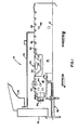
- Figure 1 shows a portion of a gas turbine combustor 10 taken around a centerline 12.
- a gas turbine includes three main parts; that is, a compressor for providing air to a plurality of combustors, and a turbine which is driven by the hot products of combustion and which, in turn, drives the compressor.
- a gas turbine there may be as many as fourteen combustors arranged around the periphery of the gas turbine.
- a unique combustor which is capable of providing a low NOx (oxides of nitrogen) output.
- a similar combustor is shown in the present invention as having a first stage or upstream combustion chamber 16 and a second stage or downstream combustion chamber 18. These two combustion stages or chambers are interconnected by a venturi throat region 20.
- the venturi throat region in general, is a restricted portion between two larger volumes; in this case, the region between the upstream and downstream combustion chambers.
- the venturi region includes an upstream wall 30 (with respect to the flow direction of the combustion products) and a downstream wall 32 interconnected by an axial wall 34.
- the upstream and downstream combustion chambers are surrounded by a combustion liner 40 which may include along its axial length a plurality of circumferential slots 42 which provide film cooling within the combustion liner.
- a combustion liner 40 which may include along its axial length a plurality of circumferential slots 42 which provide film cooling within the combustion liner.
- combustion air holes 44 which provide combustion air into the combustor liner and dilution air holes 46 which quench the combustion process.
- primary fuel nozzles 50 arranged in annular array upstream from the primary combustion chamber; and, in one typical example there may be as many as six primary fuel nozzles per combustor.
- the secondary fuel nozzle ignites the fuel flow into the second or downstream combustion chamber during periods when the upstream combustion chambers are used primarily as premix chambers. While the secondary nozzle 60 is shown as the so-called combined diffusion and premix nozzle, it should be understood that this is not a requirement of the present invention and that a simple diffusion nozzle could also be utilized in combination with the present invention.
- the combustion liner and its contents having been described in general terms, is surrounded by a flow sleeve 70 which guides compressor (not shown) discharge air in reverse flow to the combustor liner. Also shown, is an end cover 72 which closes the upstream end of the combustor and locates the secondary fuel nozzle. An annular wrapper 74 (partially shown) surrounds the flow sleeve to complete the construction of the combustor.
- FIG. 2 in combination with Figure 1, the combustor liner 40 and its contents as they pertain to the present invention are shown in schematic.
- the primary nozzles 50 are omitted from the upstream combustion chamber 16 and the secondary nozzle 60 is shown just upstream from the downstream combustion chamber 18.
- Part of the secondary nozzle is an annular can or cylinder called a centerbody 76.
- the centerbody is removable from the combustion liner with the secondary nozzle and as indicated by the louvers may be film cooled.
- the venturi throat region is described with respect to the direction of combustion products flow as including the upstream wall 30 and the downstream wall 32 interconnected by the axial wall 34.
- An annular shield 80 comprises a radially inward slanted portion 82 and an axial portion 84.
- the radially inward slanted portion is posiitoned upstream from the upstream wall 30 of the venturi and is cooled by impingement cooling holes 92. Cooling air is fed to the upstream wall impingement cooling holes thorugh air supply holes 89 located in the combustion liner.
- the axial portion of the annular shield is also impingement cooled by means of impingement cooling holes 94 in the venturi axial wall 34.
- the upstream and axial walls of the venturi were film cooled which tended to dilute the fuel/air ratio in the region of the venturi.
- the present invention will protect the venturi region from the hot combustion products without adding air to the critical burning region.
- the axial portion of the annular flow shield is further extended downstream of the venturi axial wall 34 to form an axial extended portion 86.
- the venturi axial wall is also extended in the axial direction by means of a ring 88 which defines an acute angle "a" with the downstream wall of the venturi.
- the shield axial extended portion 86 and the ring 88 are substantially coaxial with one another and the centerline axis 12 of the combustor.
- the addition of the shield axial extended portion 86 and the ring 88 act together to form a flow guide which takes the impingement cooling air downstream in the combustor and away from the flame region thereby disposing of the air in a more favorable region with respect to the maintenance of a desired fuel/air ratio.
- the shield extended portion has a free end 90 which terminates further downstream in the combustor liner than the free end of the ring 88. This causes the cooling air to inhibit hot combustion gases from contacting the downstream wall of the venturi.
- FIG. 3 is a half elevation view schematic, taken around centerline 12, wherein like numbers are assigned to like parts; there is shown a further improvement to the present invention.
- a first inner annular liner 96 extends upstream from the venturi throat region and is impingement cooled by impingement cooling holes 98 in hte combustion liner.
- a second inner annular liner 100 extends upstream from the venturi throat region but closely adjacent to the centerbody wall 76 and is impingement cooled by means of impingement cooling holes 102 in the centerbody wall.
- each inner liner with respect to its adjacent wall could be determined by knowing the desired flow of combustion air and in a manner similar to determining the dimensions of the combustion air holes.
- the achieved advantage is that the air used for impingement cooling can be added to the combustion zone without diluting the desired fuel/air ratio.
- the regions upstream from the first and second inner annular liners may be cooled by process of film cooling without adversely affecting the downstream fuel/air mixture.
- the fuel/air mixture delivered to the venturi region of a dry low NOx combustor has been improved by the cooperation of an annular shield in the venturi region and upstream first and second inner annular liners in the first or upstream combustion zone.
- the annular shield in the venturi region is impingement cooled with the impingement cooling air being dumped downstream and away from the flame in the secondary fuel nozzle.
- the upstream first and second inner annular liners are impingement cooled and dump the impingement air upstream in the first or upstream combustion zone in a metered amount so that a uniform fuel/air mixture (meaning no fuel or air pockets) can be achieved prior to combustion occurring in the venturi region.
Landscapes
- Engineering & Computer Science (AREA)
- Chemical & Material Sciences (AREA)
- Combustion & Propulsion (AREA)
- Mechanical Engineering (AREA)
- General Engineering & Computer Science (AREA)
- Gas Burners (AREA)
- Feeding, Discharge, Calcimining, Fusing, And Gas-Generation Devices (AREA)
Description
- This invention relates to gas turbine combustors and particularly to gas turbine combustors of the type having an upstream combustion chamber and a downstream combustion chamber interconnected by a venturi throat region.
- A dry low NOx combustor ist the subject of US Patent 4 292 801. In particular, that patent describes a gas turbine combustor which has an upstream combustion chamber and a downstream combustion chamber interconnected by a venturi throat region. There is an annular array of primary nozzles which input fuel into the upstream combustion chamber and a central nozzle which inputs fuel into the downstream combustion chamber. Low NOx (oxides of nitrogen) output is achieved, in part, by the method of operating the subject combustor which includes operating the combustor in a premix mode during the normal or base load such that the primary nozzles are flamed out but fuel is input through the primary nozzles to premix with combustion air whereupon the mixture is ignited in the downstream combustor chamber by the central nozzle. To achieve success in lowering NOx output in the combuster design it is important that fuel-air mixtures be maintained at specific desired levels and that there is a uniform mixture.
- In order to obtain uniform fuel-air mixtures it is also important that the combustor parts be adequately cooled due to the high temperatures found in a gas turbine combustor. One such part is the venturi region of the dual stage, dual mode combustor. Film cooling has been effected in this region on the upstream wall of the venturi throat region but it has been found that introduction of film cooling air in this region has an adverse effect on the uniform fuel-air mixture in this region such that there may be created rich/lean pockets; that is, pockets of unburned fuel or pockets of excess air.
- In the upstream combustion chamber fuel and air are premixed for ignition to occur during base load operation in the downstream combustion chamber. It is also important that the mixture profile be flat; that is, a uniform mixture. It is also important that the exact fuel air ratio be employed to improve the low NOx performance of the combustor and that the liner be adequately cooled.
- It is accordingly one objet of the present invention, to provide improved air-fuel mixing in the venturi throat region of a gas turbine combustor.
- It is another object of the invention to provide sufficient cooling of the combustor parts in the venturi throat region of a gas turbine combustor.
- It is another object of the invention to maintain the proper fuel-air ratio in the venturi throat of a gas turbine combustor.
- It is still a further object of the invention to provide an improved fuel air mixing profile in the primary combustion chamber.
- The invention itself, however, and advantages thereof may best be understood with reference to the following description and drawings.
- According to the present invention there is provided an improved gas turbine combustor of the type having an upstream combustion chamber and a downstream combustion chamber interconnected by a venturi throat region, the venturi throat region having an upstream wall and a downstream wall interconnected by an axial wall; a plurality of primary nozzles in annular array for introducing fuel into the upstream combustion chamber; a central nozzle for introducing fuel into the downstream combustion chamber; characterized in that it comprises an annular shield positioned in part, upstream from the venturi throat region, the annular shield having a radially inwardly slanted portion; and, a plurality of impingement cooling holes in the upstream wall of the venturi region directed at the radially inwardly slanted portion of the annular shield.
- In another embodiment there is a plurality of impingement cooling holes inthe axial wall of the venturi region directed at the axil a portion of the annular shield.
- In a still further embodiment a ring is attached to the venturi throat region to extend in the downstream direction with a complementary portion of the annular shield.
- Also, the upstream combustion chamber, first and second inner annular liners extend in the upstream direction and may be cooled by the impingement cooling from the combustor liner and centerbody wall respectively. The first and second inner annular liners may be open at their upstream ends to dump combustion air into the upstream combustion chamber. Film cooling holes may be provided upstream of the inner annular liner.
- Figure 1 is an elevation view of a gas turbine combustor with cutaway portions to show the present invention.
- Figure 2 is a schematic drawing of one embodiment of the present invention and its application to a gas turbine combustor.
- Figure 3 is a schematic drawing of another embodiment of the present invention and its application to a gas turbine combustor.
- Figure 1 shows a portion of a
gas turbine combustor 10 taken around acenterline 12. In US-A 4 292 801 it is made clear that a gas turbine includes three main parts; that is, a compressor for providing air to a plurality of combustors, and a turbine which is driven by the hot products of combustion and which, in turn, drives the compressor. In one model gas turbine there may be as many as fourteen combustors arranged around the periphery of the gas turbine. - In that same patent, a unique combustor is shown which is capable of providing a low NOx (oxides of nitrogen) output. A similar combustor is shown in the present invention as having a first stage or
upstream combustion chamber 16 and a second stage ordownstream combustion chamber 18. These two combustion stages or chambers are interconnected by aventuri throat region 20. The venturi throat region, in general, is a restricted portion between two larger volumes; in this case, the region between the upstream and downstream combustion chambers. The venturi region includes an upstream wall 30 (with respect to the flow direction of the combustion products) and adownstream wall 32 interconnected by anaxial wall 34. - To complete the general description of the gas turbine combustor, the upstream and downstream combustion chambers are surrounded by a
combustion liner 40 which may include along its axial length a plurality ofcircumferential slots 42 which provide film cooling within the combustion liner. In addition, there arecombustion air holes 44 which provide combustion air into the combustor liner anddilution air holes 46 which quench the combustion process. In each combustor, there are also a plurality ofprimary fuel nozzles 50 arranged in annular array upstream from the primary combustion chamber; and, in one typical example there may be as many as six primary fuel nozzles per combustor. There may also be onesecondary fuel nozzle 60 known as a combined diffusion and premix nozzle. The secondary fuel nozzle ignites the fuel flow into the second or downstream combustion chamber during periods when the upstream combustion chambers are used primarily as premix chambers. While thesecondary nozzle 60 is shown as the so-called combined diffusion and premix nozzle, it should be understood that this is not a requirement of the present invention and that a simple diffusion nozzle could also be utilized in combination with the present invention. - The combustion liner and its contents, having been described in general terms, is surrounded by a
flow sleeve 70 which guides compressor (not shown) discharge air in reverse flow to the combustor liner. Also shown, is anend cover 72 which closes the upstream end of the combustor and locates the secondary fuel nozzle. An annular wrapper 74 (partially shown) surrounds the flow sleeve to complete the construction of the combustor. - Referring now to Figure 2 in combination with Figure 1, the
combustor liner 40 and its contents as they pertain to the present invention are shown in schematic. Theprimary nozzles 50 are omitted from theupstream combustion chamber 16 and thesecondary nozzle 60 is shown just upstream from thedownstream combustion chamber 18. Part of the secondary nozzle is an annular can or cylinder called acenterbody 76. The centerbody is removable from the combustion liner with the secondary nozzle and as indicated by the louvers may be film cooled. - The venturi throat region is described with respect to the direction of combustion products flow as including the
upstream wall 30 and thedownstream wall 32 interconnected by theaxial wall 34. Anannular shield 80 comprises a radially inward slanted portion 82 and anaxial portion 84. The radially inward slanted portion is posiitoned upstream from theupstream wall 30 of the venturi and is cooled byimpingement cooling holes 92. Cooling air is fed to the upstream wall impingement cooling holes thorughair supply holes 89 located in the combustion liner. Furthermore, the axial portion of the annular shield is also impingement cooled by means ofimpingement cooling holes 94 in the venturiaxial wall 34. Formerly, the upstream and axial walls of the venturi were film cooled which tended to dilute the fuel/air ratio in the region of the venturi. The present invention will protect the venturi region from the hot combustion products without adding air to the critical burning region. - The axial portion of the annular flow shield is further extended downstream of the venturi
axial wall 34 to form an axial extendedportion 86. The venturi axial wall is also extended in the axial direction by means of aring 88 which defines an acute angle "a" with the downstream wall of the venturi. The shield axial extendedportion 86 and thering 88 are substantially coaxial with one another and thecenterline axis 12 of the combustor. The addition of the shield axial extendedportion 86 and thering 88 act together to form a flow guide which takes the impingement cooling air downstream in the combustor and away from the flame region thereby disposing of the air in a more favorable region with respect to the maintenance of a desired fuel/air ratio. - Finally, with respect to the annular shield, the shield extended portion has a
free end 90 which terminates further downstream in the combustor liner than the free end of thering 88. This causes the cooling air to inhibit hot combustion gases from contacting the downstream wall of the venturi. - Referring to Figure 3, which is a half elevation view schematic, taken around
centerline 12, wherein like numbers are assigned to like parts; there is shown a further improvement to the present invention. In theprimary combustion chamber 16, a first innerannular liner 96 extends upstream from the venturi throat region and is impingement cooled byimpingement cooling holes 98 in hte combustion liner. Likewise, a second innerannular liner 100 extends upstream from the venturi throat region but closely adjacent to thecenterbody wall 76 and is impingement cooled by means ofimpingement cooling holes 102 in the centerbody wall. By controlling the spacing of the first and second inner annular liners from the combustion liner and centerbody wall respectively the proper amount of combustion air (see flow arrows 103) for the upstream combustion chamber can be metered to the elimination of thecombustion air holes 44 in Figure 1. The exact dimensions of each inner liner with respect to its adjacent wall could be determined by knowing the desired flow of combustion air and in a manner similar to determining the dimensions of the combustion air holes. As pointed out with respect to the annular shield in the venturi region, the achieved advantage is that the air used for impingement cooling can be added to the combustion zone without diluting the desired fuel/air ratio. The regions upstream from the first and second inner annular liners may be cooled by process of film cooling without adversely affecting the downstream fuel/air mixture. - In accordance with the aforestated objects of the invention, the fuel/air mixture delivered to the venturi region of a dry low NOx combustor has been improved by the cooperation of an annular shield in the venturi region and upstream first and second inner annular liners in the first or upstream combustion zone. The annular shield in the venturi region is impingement cooled with the impingement cooling air being dumped downstream and away from the flame in the secondary fuel nozzle. Correspondingly, the upstream first and second inner annular liners are impingement cooled and dump the impingement air upstream in the first or upstream combustion zone in a metered amount so that a uniform fuel/air mixture (meaning no fuel or air pockets) can be achieved prior to combustion occurring in the venturi region.
Claims (6)
Applications Claiming Priority (2)
| Application Number | Priority Date | Filing Date | Title |
|---|---|---|---|
| US06/934,755 US4984429A (en) | 1986-11-25 | 1986-11-25 | Impingement cooled liner for dry low NOx venturi combustor |
| US934755 | 1986-11-25 |
Publications (2)
| Publication Number | Publication Date |
|---|---|
| EP0273126A1 EP0273126A1 (en) | 1988-07-06 |
| EP0273126B1 true EP0273126B1 (en) | 1990-12-19 |
Family
ID=25466010
Family Applications (1)
| Application Number | Title | Priority Date | Filing Date |
|---|---|---|---|
| EP87115435A Expired EP0273126B1 (en) | 1986-11-25 | 1987-10-21 | Gas turbine combustion chamber |
Country Status (5)
| Country | Link |
|---|---|
| US (1) | US4984429A (en) |
| EP (1) | EP0273126B1 (en) |
| JP (1) | JP2706074B2 (en) |
| DE (1) | DE3766813D1 (en) |
| NO (1) | NO167529C (en) |
Families Citing this family (47)
| Publication number | Priority date | Publication date | Assignee | Title |
|---|---|---|---|---|
| US5117636A (en) * | 1990-02-05 | 1992-06-02 | General Electric Company | Low nox emission in gas turbine system |
| JP2852110B2 (en) * | 1990-08-20 | 1999-01-27 | 株式会社日立製作所 | Combustion device and gas turbine device |
| US5199265A (en) * | 1991-04-03 | 1993-04-06 | General Electric Company | Two stage (premixed/diffusion) gas only secondary fuel nozzle |
| JP2710718B2 (en) * | 1991-11-05 | 1998-02-10 | 株式会社日立製作所 | Gas turbine combustor |
| US5253478A (en) * | 1991-12-30 | 1993-10-19 | General Electric Company | Flame holding diverging centerbody cup construction for a dry low NOx combustor |
| US5259184A (en) * | 1992-03-30 | 1993-11-09 | General Electric Company | Dry low NOx single stage dual mode combustor construction for a gas turbine |
| US5309710A (en) * | 1992-11-20 | 1994-05-10 | General Electric Company | Gas turbine combustor having poppet valves for air distribution control |
| US5487275A (en) * | 1992-12-11 | 1996-01-30 | General Electric Co. | Tertiary fuel injection system for use in a dry low NOx combustion system |
| US5454221A (en) * | 1994-03-14 | 1995-10-03 | General Electric Company | Dilution flow sleeve for reducing emissions in a gas turbine combustor |
| US5813232A (en) * | 1995-06-05 | 1998-09-29 | Allison Engine Company, Inc. | Dry low emission combustor for gas turbine engines |
| DE69625744T2 (en) * | 1995-06-05 | 2003-10-16 | Rolls-Royce Corp., Indianapolis | Lean premix burner with low NOx emissions for industrial gas turbines |
| RU2164323C2 (en) * | 1997-03-12 | 2001-03-20 | Акционерное общество открытого типа "Самарский научно-технический комплекс им. Н.Д. Кузнецова" | Flame tube of circular combustion chamber of gas-turbine engine |
| RU2131557C1 (en) * | 1997-08-20 | 1999-06-10 | Общество ограниченной ответственности "Энерго-аудит" | Intermittent air feeder with adjustable amplitude-frequency response (design versions) |
| RU2151961C1 (en) * | 1998-04-30 | 2000-06-27 | Открытое акционерное общество "Авиадвигатель" | Tubular-annular combustion chamber of gas turbine engine |
| US6314716B1 (en) * | 1998-12-18 | 2001-11-13 | Solar Turbines Incorporated | Serial cooling of a combustor for a gas turbine engine |
| RU2162988C2 (en) * | 1999-02-22 | 2001-02-10 | Открытое акционерное общество "Авиадвигатель" | Combustion chamber of gas-turbine plant |
| US6427446B1 (en) * | 2000-09-19 | 2002-08-06 | Power Systems Mfg., Llc | Low NOx emission combustion liner with circumferentially angled film cooling holes |
| JP3962554B2 (en) * | 2001-04-19 | 2007-08-22 | 三菱重工業株式会社 | Gas turbine combustor and gas turbine |
| US6430932B1 (en) * | 2001-07-19 | 2002-08-13 | Power Systems Mfg., Llc | Low NOx combustion liner with cooling air plenum recesses |
| RU2292516C2 (en) * | 2001-11-30 | 2007-01-27 | Пауэ Системс Мфг. Ллс | Combustion chamber block and method for cooling of venturi pipe in combustion chamber block |
| KR100831772B1 (en) * | 2001-11-30 | 2008-05-27 | 파워 시스템즈 엠에프지., 엘엘씨 | Combustion chamber / venturi chiller and method for nitrogen oxide low emission combustor |
| US6865892B2 (en) * | 2002-12-17 | 2005-03-15 | Power Systems Mfg, Llc | Combustion chamber/venturi configuration and assembly method |
| US7284378B2 (en) * | 2004-06-04 | 2007-10-23 | General Electric Company | Methods and apparatus for low emission gas turbine energy generation |
| US7574865B2 (en) * | 2004-11-18 | 2009-08-18 | Siemens Energy, Inc. | Combustor flow sleeve with optimized cooling and airflow distribution |
| US8028528B2 (en) | 2005-10-17 | 2011-10-04 | United Technologies Corporation | Annular gas turbine combustor |
| US7954325B2 (en) * | 2005-12-06 | 2011-06-07 | United Technologies Corporation | Gas turbine combustor |
| US8707704B2 (en) * | 2007-05-31 | 2014-04-29 | General Electric Company | Method and apparatus for assembling turbine engines |
| US20090019854A1 (en) * | 2007-07-16 | 2009-01-22 | General Electric Company | APPARATUS/METHOD FOR COOLING COMBUSTION CHAMBER/VENTURI IN A LOW NOx COMBUSTOR |
| US9404418B2 (en) * | 2007-09-28 | 2016-08-02 | General Electric Company | Low emission turbine system and method |
| US7712314B1 (en) | 2009-01-21 | 2010-05-11 | Gas Turbine Efficiency Sweden Ab | Venturi cooling system |
| US20100293952A1 (en) * | 2009-05-21 | 2010-11-25 | General Electric Company | Resonating Swirler |
| RU2519014C2 (en) * | 2010-03-02 | 2014-06-10 | Дженерал Электрик Компани | Turbine combustion chamber diffuser (versions) and turbine combustion chamber |
| US9068748B2 (en) | 2011-01-24 | 2015-06-30 | United Technologies Corporation | Axial stage combustor for gas turbine engines |
| US8479521B2 (en) | 2011-01-24 | 2013-07-09 | United Technologies Corporation | Gas turbine combustor with liner air admission holes associated with interspersed main and pilot swirler assemblies |
| US8887508B2 (en) | 2011-03-15 | 2014-11-18 | General Electric Company | Impingement sleeve and methods for designing and forming impingement sleeve |
| US9249679B2 (en) | 2011-03-15 | 2016-02-02 | General Electric Company | Impingement sleeve and methods for designing and forming impingement sleeve |
| US8915087B2 (en) | 2011-06-21 | 2014-12-23 | General Electric Company | Methods and systems for transferring heat from a transition nozzle |
| US8966910B2 (en) | 2011-06-21 | 2015-03-03 | General Electric Company | Methods and systems for cooling a transition nozzle |
| US9297534B2 (en) * | 2011-07-29 | 2016-03-29 | General Electric Company | Combustor portion for a turbomachine and method of operating a turbomachine |
| US9121613B2 (en) | 2012-06-05 | 2015-09-01 | General Electric Company | Combustor with brief quench zone with slots |
| US9127843B2 (en) | 2013-03-12 | 2015-09-08 | Pratt & Whitney Canada Corp. | Combustor for gas turbine engine |
| US9541292B2 (en) | 2013-03-12 | 2017-01-10 | Pratt & Whitney Canada Corp. | Combustor for gas turbine engine |
| US9228747B2 (en) | 2013-03-12 | 2016-01-05 | Pratt & Whitney Canada Corp. | Combustor for gas turbine engine |
| US9958161B2 (en) * | 2013-03-12 | 2018-05-01 | Pratt & Whitney Canada Corp. | Combustor for gas turbine engine |
| CN103175223B (en) * | 2013-03-19 | 2014-12-17 | 哈尔滨工程大学 | Gas circuit axial grading type dual-fuel nozzle |
| US11846426B2 (en) * | 2021-06-24 | 2023-12-19 | General Electric Company | Gas turbine combustor having secondary fuel nozzles with plural passages for injecting a diluent and a fuel |
| US12553608B1 (en) * | 2025-01-08 | 2026-02-17 | Pratt & Whitney Canada Corp. | Additively manufactured combustor liner v-band cooling ring |
Family Cites Families (13)
| Publication number | Priority date | Publication date | Assignee | Title |
|---|---|---|---|---|
| GB849255A (en) * | 1956-11-01 | 1960-09-21 | Josef Cermak | Method of and arrangements for cooling the walls of combustion spaces and other spaces subject to high thermal stresses |
| US4555901A (en) * | 1972-12-19 | 1985-12-03 | General Electric Company | Combustion chamber construction |
| US4480436A (en) * | 1972-12-19 | 1984-11-06 | General Electric Company | Combustion chamber construction |
| US4109459A (en) * | 1974-07-19 | 1978-08-29 | General Electric Company | Double walled impingement cooled combustor |
| US3905192A (en) * | 1974-08-29 | 1975-09-16 | United Aircraft Corp | Combustor having staged premixing tubes |
| JPS5331708B2 (en) * | 1974-09-12 | 1978-09-04 | ||
| US4292801A (en) * | 1979-07-11 | 1981-10-06 | General Electric Company | Dual stage-dual mode low nox combustor |
| US4413477A (en) * | 1980-12-29 | 1983-11-08 | General Electric Company | Liner assembly for gas turbine combustor |
| GB2125950B (en) * | 1982-08-16 | 1986-09-24 | Gen Electric | Gas turbine combustor |
| JPS59108053U (en) * | 1983-01-12 | 1984-07-20 | 三菱重工業株式会社 | heat shielding device |
| US4567730A (en) * | 1983-10-03 | 1986-02-04 | General Electric Company | Shielded combustor |
| JPS6082281A (en) * | 1983-10-07 | 1985-05-10 | Agency Of Ind Science & Technol | Production of combustor for gas turbine |
| CA1263243A (en) * | 1985-05-14 | 1989-11-28 | Lewis Berkley Davis, Jr. | Impingement cooled transition duct |
-
1986
- 1986-11-25 US US06/934,755 patent/US4984429A/en not_active Expired - Lifetime
-
1987
- 1987-10-21 EP EP87115435A patent/EP0273126B1/en not_active Expired
- 1987-10-21 DE DE8787115435T patent/DE3766813D1/en not_active Expired - Lifetime
- 1987-11-13 JP JP62285661A patent/JP2706074B2/en not_active Expired - Lifetime
- 1987-11-24 NO NO874894A patent/NO167529C/en not_active IP Right Cessation
Also Published As
| Publication number | Publication date |
|---|---|
| US4984429A (en) | 1991-01-15 |
| JP2706074B2 (en) | 1998-01-28 |
| NO167529C (en) | 1991-11-13 |
| NO167529B (en) | 1991-08-05 |
| NO874894L (en) | 1988-05-26 |
| JPS63150518A (en) | 1988-06-23 |
| EP0273126A1 (en) | 1988-07-06 |
| DE3766813D1 (en) | 1991-01-31 |
| NO874894D0 (en) | 1987-11-24 |
Similar Documents
| Publication | Publication Date | Title |
|---|---|---|
| US4984429A (en) | Impingement cooled liner for dry low NOx venturi combustor | |
| US8839628B2 (en) | Methods for operating a gas turbine engine apparatus and assembling same | |
| EP0878665B1 (en) | Low emissions combustion system for a gas turbine engine | |
| US5207064A (en) | Staged, mixed combustor assembly having low emissions | |
| CA2103433C (en) | Tertiary fuel injection system for use in a dry low nox combustion system | |
| JP4902208B2 (en) | Venturi for combustor | |
| US3643430A (en) | Smoke reduction combustion chamber | |
| US4982570A (en) | Premixed pilot nozzle for dry low Nox combustor | |
| US5193346A (en) | Premixed secondary fuel nozzle with integral swirler | |
| US6301899B1 (en) | Mixer having intervane fuel injection | |
| EP1371906B1 (en) | Gas turbine engine combustor can with trapped vortex cavity | |
| US4356698A (en) | Staged combustor having aerodynamically separated combustion zones | |
| US5645410A (en) | Combustion chamber with multi-stage combustion | |
| EP1193447B1 (en) | Multiple injector combustor | |
| EP0488556B1 (en) | Premixed secondary fuel nozzle with integral swirler | |
| EP1985923A2 (en) | Methods and systems to facilitate reducing flashback/flame holding in combustion systems | |
| EP0773410B1 (en) | Fuel and air mixing tubes | |
| EP0269824B1 (en) | Premixed pilot nozzle for dry low nox combustor | |
| CA2390446C (en) | Gas turbine combustor | |
| KR20030036174A (en) | Annular combustor for use with an energy system | |
| CA2468646C (en) | Combustion chamber/venturi cooling for a low nox emission combustor | |
| GB2107448A (en) | Gas turbine engine combustion chambers | |
| USRE30160E (en) | Smoke reduction combustion chamber | |
| CA1315995C (en) | Impingement cooled liner for dry low nox venturi combustor | |
| JPH0230409B2 (en) |
Legal Events
| Date | Code | Title | Description |
|---|---|---|---|
| PUAI | Public reference made under article 153(3) epc to a published international application that has entered the european phase |
Free format text: ORIGINAL CODE: 0009012 |
|
| AK | Designated contracting states |
Kind code of ref document: A1 Designated state(s): CH DE FR GB IT LI NL |
|
| 17P | Request for examination filed |
Effective date: 19881221 |
|
| 17Q | First examination report despatched |
Effective date: 19890420 |
|
| GRAA | (expected) grant |
Free format text: ORIGINAL CODE: 0009210 |
|
| AK | Designated contracting states |
Kind code of ref document: B1 Designated state(s): CH DE FR GB IT LI NL |
|
| ET | Fr: translation filed | ||
| REF | Corresponds to: |
Ref document number: 3766813 Country of ref document: DE Date of ref document: 19910131 |
|
| ITF | It: translation for a ep patent filed | ||
| PLBE | No opposition filed within time limit |
Free format text: ORIGINAL CODE: 0009261 |
|
| STAA | Information on the status of an ep patent application or granted ep patent |
Free format text: STATUS: NO OPPOSITION FILED WITHIN TIME LIMIT |
|
| 26N | No opposition filed | ||
| ITTA | It: last paid annual fee | ||
| REG | Reference to a national code |
Ref country code: GB Ref legal event code: IF02 |
|
| PGFP | Annual fee paid to national office [announced via postgrant information from national office to epo] |
Ref country code: NL Payment date: 20021011 Year of fee payment: 16 |
|
| PG25 | Lapsed in a contracting state [announced via postgrant information from national office to epo] |
Ref country code: NL Free format text: LAPSE BECAUSE OF NON-PAYMENT OF DUE FEES Effective date: 20040501 |
|
| NLV4 | Nl: lapsed or anulled due to non-payment of the annual fee |
Effective date: 20040501 |
|
| PGFP | Annual fee paid to national office [announced via postgrant information from national office to epo] |
Ref country code: GB Payment date: 20061025 Year of fee payment: 20 |
|
| PGFP | Annual fee paid to national office [announced via postgrant information from national office to epo] |
Ref country code: CH Payment date: 20061027 Year of fee payment: 20 |
|
| PGFP | Annual fee paid to national office [announced via postgrant information from national office to epo] |
Ref country code: IT Payment date: 20061031 Year of fee payment: 20 |
|
| PGFP | Annual fee paid to national office [announced via postgrant information from national office to epo] |
Ref country code: DE Payment date: 20061130 Year of fee payment: 20 |
|
| REG | Reference to a national code |
Ref country code: GB Ref legal event code: PE20 |
|
| REG | Reference to a national code |
Ref country code: CH Ref legal event code: PL |
|
| PG25 | Lapsed in a contracting state [announced via postgrant information from national office to epo] |
Ref country code: GB Free format text: LAPSE BECAUSE OF EXPIRATION OF PROTECTION Effective date: 20071020 |
|
| PGFP | Annual fee paid to national office [announced via postgrant information from national office to epo] |
Ref country code: FR Payment date: 20061017 Year of fee payment: 20 |