Background Of The Invention:
-
When people work, first thing they have to do is to stabilize an object, then process with utensils.
-
Clamping is specifically important while working.
-
Because of the various sizes of objects, various sized vises are sold.
-
A big size vise is heavier in weight and occupies more space.
-
Because of the restraint in its structure, weight and space it occupies, the maximum clamping size cannot be enlarged anymore.
-
We are expecting to break through this traditional structural limitation exposed by a front moveable clamp jaw system and a rear moveable clamp jaw system.
-
An ordinary vise sold in a market consists of one fixed body and one moveable body, with a sliding structure and a leading shaft that drives a jaw to clamp.
-
Usually, a clamping distance is limited by the size of its structure.
-
If a longer clamping distance is needed, a longer size vise must be used. This causes inconvenience in package and occupies more space.
-
This design employs multiple-layer, paralleled upper and lower dual movement system to enlarge sliding range. This structural design shortens the body length of the vise that can clamp on the same size object as the above stated two parts structured vise which consists of a fixed body and a moveable body.
-
The improved design minimizes its size and space it occupies. Moreover, this design can speed up the adjustment for a longer object and appears to be more convenient to use.
Summary Of The Invention:
-
This design, mainly by inserting at least one set of middle sliding socket between a fixed body and a moveable body of a traditional vise.
-
This middle sliding socket mounts on a vertical sliding route of a fixed body and enables itself to make an adjusting slide. The position adjusting holes on it determines its relation with the fixed body.
-
Inside this middle sliding socket, there is an inner sliding rail which snaps to the root part of the moveable jaw. There is also a fixed threaded opening shaft base into which a leading threaded shaft can be screwed and drives a moveable jaw to perform a clamping or releasing function together with a fixed jaw.
-
One step ahead, another design is to have the paralleled upper and lower system. That is one set of a front moveable jaw with its independent driving threaded shaft, and one set of a rear moveable jaw with its independent driving threaded shaft are separately snapped on the same fixed body in parallel. This enlarges the ratio between the clamping size and the space a vise occupies. It widens a clamping extent of a clamp structure.
Detailed Description Of The Invention:
-
A traditional vise normally has a constant clamping distance. Because of this, there has been always some limitation on practical application. This design, by inserting a middle sliding socket on a sliding surface between a fixed body and a moveable jaw of a traditional vise, enlarges its clamping extent.
-
For example, the original clamping area of from 0 to 100mm is enlarged to have multiple function areas from 0 to 100mm, from 100 to 200mm, from 200 to 300mm. Following are the practical implementation examples of which this design is applied to various type of vises.
-
There is a middle vertical sliding rail between a fixed body and a moveable body. There are two types: A moveable jaw is in the front or a moveable jaw which consists of a pigeon tail shaped groove is in the rear.
-
Following figures are various implementation examples:
-
Figure 1, 2 and 3 show the structural example that this design is applied to a front moveable jaw which is driven by a leading threaded shaft. In the figures, there is the third middle sliding socket 1 consisting of at least one layer between a fixed clamp body and a moveable body. By adjusting the distance between a middle socket 1 and a fixed jaw 2, the clamping extent between a moveable jaw 3 and a fixed jaw 2 can be changed. Its main structural feature include:
-
--One set of a fixed vise body 20 is affixed on a work table. A fixed jaw 2 that performs the function of clamping face is on it. Its main body has a vertical sliding rail 21 that accepts a middle sliding socket 1 and a hole 22 into which a position locking bolt 23 can be screwed to lock a sliding socket 1.
-
This position fixing hole 22 may be set on both sides of the main body or on its top part.
-
--At least one set of a middle sliding socket is placed in a middle, vertical sliding rail 21 of a fixed body 20 and enables to adjust itself by a sliding movement. On its top or both sides, there are at least two position locking holes 12 to screw position fixing bolts 23.
-
The position locking bolts 23 performs the function of adjusting its distance with a fixed body 2. There is a vertical sliding rail 11 inside for a sliding root portion of a moveable jaw 3 to be placed in it. (In case there are multiple layers, it snaps on the next middle sliding socket.) There is also a shaft base 13 with a threaded hole for inserting a threaded shaft 31 that drives a moveable jaw 3.
-
--There is a piercing opening on a moveable jaw 3 to insert a driving leading threaded shaft 31. A leading threaded shaft 31 is screwed in a threaded hole of a shaft base 13 in a middle sliding socket 1. Its root portion is snapped into a sliding rail 11 of a middle sliding socket 1. By driving a leading shaft, its clamp holding surface and a clamp holding face of a fixed body 2 perform a tight clamping or releasing action.
-
--A driving threaded shaft 31 is used to drive a moveable jaw 3 and allow a middle sliding socket 1 to make the facing movement.
-
--A position locking bolt 23 is used to lock the adjusted position between a middle sliding socket 1 and a fixed body 2.
-
When it is put into a practical application, a position locking bolt 23 functions as a selector of the location of a fixed body 2 and a middle sliding socket 1. Because it does not obstruct the relation between a middle sliding socket 1 and a moveable jaw 3, it may be applied to increase or decrease the extent of a clamping area.
-
For example, to clamp a larger work object, it can be done by just extending a middle sliding socket 1 in the direction of a moveable jaw 3. It is effective to clamp a general work object, such as a work object with a larger frame.
-
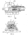
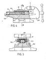
The Figures 4 and 5 show the structure that this design is applied to drive a rear moveable jaw 30 with a leading threaded shaft 31. In the figure, the main part is that between a vise fixing body 200 and a moveable body 30, attach a position adjustable third middle sliding socket 10 that has at least one layer. By adjusting the distance between a middle socket 10 and a moveable jaw 30, the clamping area between a moveable jaw 30 and a fixed jaw 2 can be adjusted. Its main structural features include:
-
--One set of a vise fixing body 200 is attached on a work table. On it, there is one clamping face A that is a fixed jaw 2. On the back part of the main body, there is a vertical, pigeon tail shaped rail 201 for snapping a middle sliding socket 10.
-
--At least one set of a middle sliding socket 10 is snapped in a vertical sliding rail 201 inside a fixed body 200. An adjusting drive is performed by driving a threaded shaft 31. On it, there are at least two sets of position locking holes 102. The distance of a moveable jaw 30 is adjusted by a position locking threaded bolt 203. Also there is a vertical second sliding rail to snap the bottom part of a moveable jaw 30. (In case of multiple layers, to snap the next middle sliding socket.) There is a threaded hole to screw in a threaded shaft 31 that will be used to drive.
-
--On the top or both sides of a moveable jaw 30, there are holes into which threaded bolts 203 are screwed for locking the position of a middle sliding socket 10. Its root portion is used to snap a sliding rail of a middle sliding rocket 10. The above stated position locking holes 102 and a position locking threaded bolts 203 function to adjust the distance of a middle sliding socket 10.
-
--A driving threaded shaft 31 issued to drive a middle sliding socket 10 and activate the clamping surfaces A of a moveable jaw and a fixed body 200 to make a movement toward each other.
-
--A position locking threaded bolt 203 is used to lock the pre-selected position between a middle sliding socket 10 and a moveable jaw 30. Its practical application is the same as the above stated Figure 1. A repeating explanation is avoided here.
-
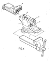
The Figure 6, 7, and 8 show the structure of this design, one step ahead.
-
A front moveable jaw and a rear moveable jaw share one common fixing body. In the figures, there are:
-
--On the bottom portion of a fixed main body 4, there is a sliding hole 41 for a front moveable jaw 5 to be inserted into and to make a sliding movement.
-
Inside the sliding hole 41, there is a front shaft base 42 which has a threaded hole. A vertical, pigeon tail shaped groove 43 is made on a fixed body 4 to snap a rear moveable jaw 6. Inside the pigeon tail shaped groove 43, there is another rear shaft base 44 which has a threaded hole.
-
--On the top of a front moveable jaw 5, there is a clamping surface facing inward. A piercing opening is drilled on the front bottom part to insert a front leading threaded shaft 50 and snaps to a front shaft base 42 inside a fixed body 4. A front leading threaded shaft 50 has a larger head portion that can produce the pressing function against a front moveable jaw when it is turned to clamp.
-
A stop pin spring and a detent are installed on the exposing section of the piercing hole inner side wall. It is used to activate the retreat of a front moveable jaw under a counter-wise turning.
-
--On a rear moveable jaw 6, there is a clamping surface that faces a clamping surface of a front moveable jaw 5. On the bottom part, there is a slideable pigeon tail which snaps into a pigeon tail shaped groove 43 of a fixed body 4. Its end portion extends downward, and has a piercing hole to insert a rear leading threaded shaft 60. This leading threaded shaft 60 is screwed into a shaft base 44 which is located between the top side of a fixed body 4 and a pigeon tail shaped groove 43. There is a larger head part on its outer end which functions to press and clamp tightly when a rear moveable jaw 6 is turned and pressed.
-
A stop pin spring and a detent is installed on the exposing section of the piercing hole inner side wall. It is used to activate the retreat of a front moveable jaw under a counter-wise turning. Thus turning a rear leading threaded shaft 60, it activates a rear moveable jaw 6.
-
In the above stated structure, the same threaded groove distance shafts may be applied to two sets of the leading threaded shafts 50 and 60 for producing the clamping power. Or one step ahead, one set uses a fine threaded shaft and the other set uses a coarse threaded shaft. A coarse threaded shaft is used for rough adjustment and a fine threaded shaft is used to produce the stronger clamping power under the same turning torque.
-
In the practical application, we find the fact that this design, under the same weight and space, it has a larger clamp holding size. The above stated rear sliding jaw 6, one step ahead, may have the specific features as shown in the Figure 9 and 10. Eliminate a rear leading threaded shaft 60 and a rear shaft base 44, make one position locking threaded and stepped hole between a jaw and a flat surface. Make at least two vertical position locking holes 45 on a pigeon tail shaped groove of the fixed body 4. By inserting a threaded position locking bolt 7 into the above stated position locking threaded and stepped hole on a rear sliding jaw 6 and one of the pre-selected position locking holes 45 on the fixed body 4, the adjustment between a rear movement jaw 6 and a fixed body 4 can be made.
-
Summing up, this application, by adding a middle sliding socket to adjust the extent, enlarge the applicable area for a vise. It is economical. Please examine according to the law.
Brief Description Of The Drawing:
-
- Figure 1. A solid, dissolved structural view of a front moveable jaw.
- Figure 2. A sectional view of a front moveable jaw structure.
- Figure 3. A sectional view of A-A in the Figure 2.
- Figure 4. A sectional view of a rear moveable jaw structure.
- Figure 5. A sectional view of B-B in the Figure 4.
- Figure 6. A solid, dissolved structural view of a front and rear moveable jaws sharing a fixed body.
- Figure 7. A sectional view of a front and rear moveable jaws sharing a fixed body.
- Figure 8. A sectional view of C-C in the Figure 7.
- Figure 9. A sectional view of another implementation example of a front and rear moveable jaws sharing a fixed body.
- Figure 10. A sectional view of D-D in the Figure 9.
Features of the Invention.
-
- 1. This is an improved dual movement system, double range vise. The main point is that between a fixed vise body and a front moveable jaw, attach the third middle sliding socket consisting of at least one layer. By adjusting the distance between the middle socket and a fixed jaw, the clamping extent between a moveable jaw and a fixed jaw can be changed.
Its main structural features include:
One set of a fixed vise body is affixed on a work table. A clamping face A is on it. Its main body has a vertical sliding rail that accepts a middle sliding socket and a hole into which a position locking bolt can be screwed to lock a sliding socket.
At least one set of a middle sliding socket is placed in a middle, vertical sliding rail of a fixed body and enables to adjust itself by a sliding movement. There are position locking holes on it. The position locking threaded bolt is used to adjust its distance with a fixed body. There is a vertical sliding rail inside for a sliding root portion of a moveable jaw to be placed in it. (In case there are multiple layers, it snaps on the next middle sliding socket.) There is also a shaft base with a threaded hole for inserting a threaded shaft that drives a removeable jaw.
There is a piercing opening on a moveable jaw to insert a driving leading threaded shaft. A leading threaded shaft is screwed in a threaded hole of a shaft base in a middle sliding socket. Its root portion is snapped into a sliding rail of a middle sliding socket. By driving a leading shaft, its clamp holding surface and a clamp holding face of a fixed body perform a tight clamping or releasing action.
A driving threaded shaft is used to drive a moveable jaw and allow a middle socket to make the facing movement.
A position locking bolt is used to lock the adjusted position between a middle sliding socket and a fixed body.
- 2. The structure as stated in Feature 1, one step ahead, it may have a specific structure that a rear moveable jaw is driven by a leading threaded shaft. The main part is that between a clamp fixing body and a moveable body, attach a position adjustable third middle sliding socket that has at least one layer. By adjusting the distance between a middle socket and a moveable jaw, the clamping area between a moveable jaw and a fixed jaw can be adjusted. Its main structural features include:
One set of a vise fixing body is attached on a work table. On it, there is one clamping face A. On the back part of the main body, there is a vertical, pigeon tail shaped sliding rail for snapping a middle sliding pocket.
At least one set of a middle sliding socket is snapped in a vertical sliding rail inside a fixed body. An adjusting drive is performed by driving a threaded shaft. On it, there are position locking holes. The distance of a moveable jaw is adjusted by a position locking threaded bolt. Also, there is a vertical, second sliding rail to snap the bottom part of a moveable jaw. (In case of the multiple layers, to snap the next middle sliding socket.) There is a threaded hole to screw in a threaded shaft that will be used to drive.
On a moveable jaw, there are holes into which threaded bolts are screwed for locking the position of a middle sliding socket. Its root portion is used to snap a sliding rail of a middle sliding socket. The above stated position locking holes and a position locking threaded bolts function to adjust the distance of a middle sliding socket.
A driving threaded socket is used to drive a middle sliding socket and activate the clamping surfaces of a moveable jaw and a fixed body to make a movement toward each other.
A position locking threaded bolt is used to lock the pre-selected position between a middle sliding socket and a moveable jaw.
- 3. The dual movement system, double range vise structure as stated in Feature 1, mainly has separately installed front and rear moveable jaws each independently driven by a threaded shaft. A fixed body is shared by them from upper and lower sides. The main features include:
On the bottom portion of a fixed main body, there is a sliding hole for a front moveable jaw to be inserted into and to make a sliding movement. Inside the sliding hole, there is a front shaft base which has a threaded hole. A vertical, pigeon tail shaped groove is made on a fixed body to snap a rear moveable jaw. Inside the pigeon tail shaped groove, there is another rear shaft base which has a threaded hole.
On the top of a front moveable jaw, there is a clamping surface facing inward. A piercing opening is drilled on the front bottom part to insert a front leading threaded shaft and snaps to a front shaft base inside a fixed body. A front leading threaded shaft has a large head portion that can produce the pressing function against a front moveable jaw when it is turned to clamp.
A stop pin spring and a detent are installed on the exposing section of the piercing hole inner side wall. It is used to activate the retreat of a front moveable jaw under a counter-wise turning.
On a rear moveable jaw, there is a clamping surface that faces a clamping surface of a front moveable jaw. On the bottom part, there is a slideable pigeon tail which snaps into a pigeon tail shaped groove of a fixed body. Its end portion extends downward and has a piercing hole to insert a rear leading threaded shaft. This leading threaded shaft is screwed into a shaft base which is located between the top side of a fixed body and a pigeon tail shaped groove.
There is a larger head part on its outer end which functions to press and clamp tightly when a rear moveable jaw is turned and pressed.
A top pin spring and a detent is installed on the exposing section of the piercing hole inner side wall. It is used to activate the retreat of a front moveable jaw under a counter-wise turning. Thus turning a rear leading threaded shaft, its activates a rear moveable jaw.
- 4. The structure of two sets of the leading threaded shafts in the above stated Feature 3, may apply the same threaded groove distance shafts for producing the clamping power. Or one step ahead, one of them may apply a coarse threaded shaft for making a general, rough adjustment. A fine threaded shaft may be used for the other to produce the stronger clamping power under. the same turning torque.
- 5. The front sliding jaw as stated in Feature 3, one step ahead, may have a specific feature. Eliminate a rear leading threaded shaft and a rear shaft base. Make one position locking threaded and stepped hole between a jaw and a flat surface. Make at least two vertical position locking holes on a pigeon tail shaped groove of the fixed body. By inserting a threaded position locking bolt into the position locking threaded and stepped hole on a rear sliding jaw and one of the pre-selected position locking holes on the fixed body, the adjustment between a rear moveable jaw and a fixed body can be made.