EP0272770B1 - Tubular connector - Google Patents
Tubular connector Download PDFInfo
- Publication number
- EP0272770B1 EP0272770B1 EP87307097A EP87307097A EP0272770B1 EP 0272770 B1 EP0272770 B1 EP 0272770B1 EP 87307097 A EP87307097 A EP 87307097A EP 87307097 A EP87307097 A EP 87307097A EP 0272770 B1 EP0272770 B1 EP 0272770B1
- Authority
- EP
- European Patent Office
- Prior art keywords
- sleeve
- tubular
- latching
- latching fingers
- tubular members
- Prior art date
- Legal status (The legal status is an assumption and is not a legal conclusion. Google has not performed a legal analysis and makes no representation as to the accuracy of the status listed.)
- Expired - Lifetime
Links
- 238000007789 sealing Methods 0.000 claims description 24
- 239000012530 fluid Substances 0.000 claims description 10
- 230000000452 restraining effect Effects 0.000 claims description 5
- 230000000694 effects Effects 0.000 claims description 3
- 238000013022 venting Methods 0.000 claims description 3
- 239000002184 metal Substances 0.000 claims description 2
- 238000009434 installation Methods 0.000 description 2
- 230000013011 mating Effects 0.000 description 2
- 241000282472 Canis lupus familiaris Species 0.000 description 1
- 230000002411 adverse Effects 0.000 description 1
- 230000001627 detrimental effect Effects 0.000 description 1
- -1 dirt Substances 0.000 description 1
- 239000012535 impurity Substances 0.000 description 1
- 239000000463 material Substances 0.000 description 1
- 230000002250 progressing effect Effects 0.000 description 1
- 230000000717 retained effect Effects 0.000 description 1
- 239000013049 sediment Substances 0.000 description 1
Images


Classifications
-
- E—FIXED CONSTRUCTIONS
- E21—EARTH OR ROCK DRILLING; MINING
- E21B—EARTH OR ROCK DRILLING; OBTAINING OIL, GAS, WATER, SOLUBLE OR MELTABLE MATERIALS OR A SLURRY OF MINERALS FROM WELLS
- E21B33/00—Sealing or packing boreholes or wells
- E21B33/02—Surface sealing or packing
- E21B33/03—Well heads; Setting-up thereof
- E21B33/035—Well heads; Setting-up thereof specially adapted for underwater installations
- E21B33/038—Connectors used on well heads, e.g. for connecting blow-out preventer and riser
-
- E—FIXED CONSTRUCTIONS
- E21—EARTH OR ROCK DRILLING; MINING
- E21B—EARTH OR ROCK DRILLING; OBTAINING OIL, GAS, WATER, SOLUBLE OR MELTABLE MATERIALS OR A SLURRY OF MINERALS FROM WELLS
- E21B17/00—Drilling rods or pipes; Flexible drill strings; Kellies; Drill collars; Sucker rods; Cables; Casings; Tubings
- E21B17/02—Couplings; joints
-
- E—FIXED CONSTRUCTIONS
- E21—EARTH OR ROCK DRILLING; MINING
- E21B—EARTH OR ROCK DRILLING; OBTAINING OIL, GAS, WATER, SOLUBLE OR MELTABLE MATERIALS OR A SLURRY OF MINERALS FROM WELLS
- E21B23/00—Apparatus for displacing, setting, locking, releasing or removing tools, packers or the like in boreholes or wells
- E21B23/04—Apparatus for displacing, setting, locking, releasing or removing tools, packers or the like in boreholes or wells operated by fluid means, e.g. actuated by explosion
- E21B23/042—Apparatus for displacing, setting, locking, releasing or removing tools, packers or the like in boreholes or wells operated by fluid means, e.g. actuated by explosion using a single piston or multiple mechanically interconnected pistons
-
- E—FIXED CONSTRUCTIONS
- E21—EARTH OR ROCK DRILLING; MINING
- E21B—EARTH OR ROCK DRILLING; OBTAINING OIL, GAS, WATER, SOLUBLE OR MELTABLE MATERIALS OR A SLURRY OF MINERALS FROM WELLS
- E21B43/00—Methods or apparatus for obtaining oil, gas, water, soluble or meltable materials or a slurry of minerals from wells
- E21B43/01—Methods or apparatus for obtaining oil, gas, water, soluble or meltable materials or a slurry of minerals from wells specially adapted for obtaining from underwater installations
- E21B43/013—Connecting a production flow line to an underwater well head
-
- F—MECHANICAL ENGINEERING; LIGHTING; HEATING; WEAPONS; BLASTING
- F16—ENGINEERING ELEMENTS AND UNITS; GENERAL MEASURES FOR PRODUCING AND MAINTAINING EFFECTIVE FUNCTIONING OF MACHINES OR INSTALLATIONS; THERMAL INSULATION IN GENERAL
- F16L—PIPES; JOINTS OR FITTINGS FOR PIPES; SUPPORTS FOR PIPES, CABLES OR PROTECTIVE TUBING; MEANS FOR THERMAL INSULATION IN GENERAL
- F16L37/00—Couplings of the quick-acting type
- F16L37/002—Couplings of the quick-acting type which can be controlled at a distance
-
- Y—GENERAL TAGGING OF NEW TECHNOLOGICAL DEVELOPMENTS; GENERAL TAGGING OF CROSS-SECTIONAL TECHNOLOGIES SPANNING OVER SEVERAL SECTIONS OF THE IPC; TECHNICAL SUBJECTS COVERED BY FORMER USPC CROSS-REFERENCE ART COLLECTIONS [XRACs] AND DIGESTS
- Y10—TECHNICAL SUBJECTS COVERED BY FORMER USPC
- Y10S—TECHNICAL SUBJECTS COVERED BY FORMER USPC CROSS-REFERENCE ART COLLECTIONS [XRACs] AND DIGESTS
- Y10S285/00—Pipe joints or couplings
- Y10S285/92—Remotely controlled
Definitions
- Tubular connectors are commonly used in subsea and downhole locations. In such locations the connector are exposed to corrosive conditions and to the wear and detrimental affects of sediment, dirt, and circulating fluids. Further in such applications for a tubular connector, it is most advantageous if the tubular connector has as small a diameter as possible to conserve diametrical space.
- tubular connectors which could be remotely operated.
- a typical example of such connectors is the collet type of connectors which are disclosed in U. S. Patent Nos. 3,321,217 and 3,353,595.
- Each of these devices are operated by a plurality of pressure responsive means or hydraulic actuators which cam a clamping means into engagement with mating portions of the end of the tubular member opposed to the tubular member carrying the pressure responsive means.
- Such connectors are not suitable for use in spaces of confined diameter. They also have the disadvantage that the latching elements are not protected from the corrosive and other adverse condition of the environment in which the unit is to be installed.
- U. S. Patent No. 3,241,864 which includes a lower lead-in funnel shape to guide the entrance of the upper end of the tubular member into the connector.
- the locking is automatically accomplished through the use of a plurality of resilient circumferentially spaced fingers extending from an upper tubular body and such fingers latch into and out of a latching groove on the exterior of the tubular member which is to be engaged by the connector.
- U.S. Patent No. 3,918,485. includes the flexible latching fingres and also adds an actuated camming collar which cams the fingers into their latching position or releases them from such position. The latching fingers are exposed to the local environment.
- GB-A-2165908 describes a tubular connector in which radially movable locking dogs are actuated by an axially slidable sleeve to latch together two tubular members.
- FIGURE 2 of the drawings Another structure of the prior art is hereinafter disclosed with respect to the structure disclosed in FIGURE 2 of the drawings. While such structure has been found suitable for downhole applications, it does not protect its latching elements from the environment in which it is installed. In all prior art structures of tubular connectors, such structures do not protect their latching means and many also are not suitable for installation in spaces of restricted diameter.
- a tubular connector comprising a first tubular member and a second tubular member, a sleeve slidably mounted around the exterior of the first tubular member, and a plurality of latching fingers carried within the sleeve, each latching finger having an internal profile which can be moved into engagement with an exterior profile on the tubular members to latch them together when the sleeve is moved axially to a latching position, said sleeve having a surface which engages said latching fingers when they are in their restrained position and urges them to a position in which the profiles interengage, at least a portion of said sleeve being spaced from one of the tubular members to form a pressure chamber, and a port extending through said one tubular member into said pressure chamber for supplying fluid pressure to said chamber to effect movement of said sleeve, means provided for restraining the axial movement of the latching fingers when said profile is in alignment with the exterior profile of the tubular members, characterised in that
- One embodiment of the present invention provides a tubular connector including a first tubular member with an enlarged external end portion, an external rib space from said enlarged external end portion and an internal tapered end sealing surface, a second tubular member having an enlarged external end portion and an internal tapered end sealing surface, a sleeve surrounding and slidable on said second tubular member and having an enlarged end extending beyond said second tubular member with an inner surface tapering inwardly and toward said second tubular member, said sleeve being spaced from said second tubular member to provide an annular pressure chamber for moving said sleeve along said second tubular member, a plurality of latching fingers positioned within said sleeve and having projections for engaging said external enlargements of said tubular members, mating cam surfaces on said latching fingers and within said sleeve whereby movement of said sleeve to extend beyond said second tubular member cams said latching fingers into secure engagement with said enlargements and brings said sleeve enlargement into
- FIGURE 1 subsea well 10 is illustrated including mudline support 12 on which flowline connector 14 is supported, wellhead 16 within wellbore 18 and connected through connector 20, master valve assembly 22, connector 24 and flowline extension spool 26 to the equipment on support 12 including connector 14.
- Connectors 14, 20 and 24 are the type of connector applications for which the tubular connector of the present invention is suitable.
- Connector 28 includes first tubular member 30 having on its upper end internal tapered end sealing surface 32 and external engagement grooves 34, and second tubular member 36 having flange 38 on its upper end, and lower end internal tapered sealing surface 40 and external latch foot groove 42 on its lower end, sleeve 44 surrounding second tubular member 36 with latching fingers 46 positioned between the lower interior surface 48 of sleeve 44 and the lower exterior of second tubular member 36.
- Latching fingers 46 include body 50, internal foot 52 on their upper end which projects into latch foot groove 42 and internal lands or ribs 54 which are spaced and sized for latching engagement within external engagement grooves 34 in the upper end of first tubular member 30.
- Sleeve 44 is slidably mounted on the exterior of second tubular member 36 and includes internal rib 56 which projects into upper external recess 58 in second tubular member 36. With suitable sealing recess 58 defines upper and lower piston chambers 60 and 62 to which hydraulic fluid is delivered alternately through passages 64 and 66 respectively.
- sleeve 44 is moved downwardly on member 36 and causes latching fingers 46 to be cammed inwardly by the engagement of the internal surface of sleeve with the external surfaces of fingers 46 into latching engagement within engagement grooves 34 and latch foot groove 42 to thereby complete the connection between the two tubular members.
- Guide rods 68 are secured to the upper end of sleeve 28 and extend through suitable openings in flange 38.
- tubular connector 28 has its latching fingers and the interior of its sleeve 44 below chambers 60 and 62 exposed to the environment surrounding tubular members 30 and 32. Further, with the prior art connector 28, difficulty can be encountered with the entry of the upper end of first tubular member 30 within the latching fingers 44.
- Connector 70 includes lower tubular member 72 having upper internal tapered sealing surface 74, upper external annular hub or rib 76 and lower external rib 78 spaced below upper rib 76 by a preselected distance as hereinafter explained.
- Connector 70 also includes upper tubular member 80, sleeve 82 and latching fingers 84.
- Upper tubular member 80 includes lower internal tapered sealing surface 86 with seal ring 88 positioned thereon and retained by its external rib 90 being engaged by snap ring 92 in internal groove 94 near the lower end of tubular member 80 as best shown in FIGURE 7.
- Tubular member 80 includes lower outer hub or rib 96, external setting rib 98 spaced above rib 96, external release rib 100 spaced above rib 98 and chamber defining external rib 102 spaced above rib 100 all as shown and hereinafter described in detail.
- O ring 101 is positioned in groove 103 on the outer surface or rib 102 for sealing against the interior surface of sleeve 82.
- Sealing ring 104 is positioned in surrounding relationship to the exterior of upper tubular member 80 spaced above rib 102 and includes internal seal 106 and external seal 108 which seal respectively against the exterior surface of tubular member 80 and the interior of sleeve 82.
- Lock ring 110 is threaded onto tubular member 80 as shown and provides the upper shoulder against which sealing ring 104 abuts.
- Sleeve 82 surrounds the lower end of upper tubular member 80 with its lower end projecting beyond the lower end of member 80 as member 80 is being lowered toward lower tubular member 72 as shown in FIGURE 3.
- Sleeve 82 includes internal rib 112 with O ring 114 positioned in groove 116 on the interior of rib 112 and adapted to seal against exterior surface of upper tubular member 80 between rib 102 and sealing ring 104.
- Sleeve 82 includes lower internal surface 118 which tapers inwardly and upwardly to receive the exterior of latching fingers 84 in their unlatched position.
- Tapered shoulder 120 is positioned at the upper end of surface 118 and tapers inwardly and upwardly between surface 118 and upper internal tapered surface 122.
- Ring 124 is threaded onto the lower end of sleeve 82 and includes internal groove 126 in which O ring 128 is positioned, upper surface 130 which tapers upwardly and inwardly to receive the lower ends of latching fingers 84 and lower surface 132 which has a shallow taper to assist in the centering of tubular member 72 within sleeve 82.
- Ring 134 is threaded onto the upper end of sleeve 82 and includes internal wiping seal 136 which engages the exterior of tubular member 80 above ring 110.
- Latching fingers 84 include body 138 with outer surface 140 which tapers upwardly and inwardly, lower tapered surface 142 which engages surface 130 of ring 124, internal groove 144 with tapered shoulders 146 and 148 at its upper and lower ends, upper internal groove 150 which terminates in rib 152 with lower shoulder 154 and upper shoulder 156.
- Groove 144 is sized so that shoulders 146 and 148 can engage shoulder 158 on the upper portion of rib 96 on upper tubular member and shoulder 160 on the lower portion of external rib 76 on lower tubular member 72 in clamping engagement to retain upper tubular member 80 and lower tubular member 72 in tight sealing engagement with seal ring 88.
- Improved tubular connector 70 is made up with sleeve 82 positioned around upper tubular member 80 as shown in FIGURE 3 with lower ring 124 extending below the lower end of upper tubular member 80. In this position the unit is lowered into position aligned with and approaching the upper end of lower tubular member 72. As ring 124 reaches hub 76 of lower tubular member 72, its tapered surface 132 aids in centering lower tubular member 72 within sleeve 82. Once hub 76 enters the interior of ring 124 it is in a cylindrical path leading to its engaged and sealed position with respect to the lower end of upper tubular member 80 and sealing ring 88. This cylindrical path is formed by the interior of ring 124 and the interior of the lower portion of latching fingers 84 which extend upward into surrounding relationship to hub 96 on upper tubular member 80.
- O ring 128 on the interior of ring 124 is positioned in sealing engagement with the exterior surface of rib 78 and seal 136 seals against the exterior of tubular member 82 to isolate latching fingers 84 and the interior of sleeve 82 surrounding tubular member 72 and 80 and setting and release chambers 164 and 168 from the fluids, dirt, impurities and other undesirable materials contained in the environment surrounding and within tubular connector 70.
- tubular connector 70 is accomplished by venting hydraulic pressure from setting chamber 164 through passage 162 and delivering hydraulic pressure through passage 166 into release chamber 168.
- the pressure urges sleeve 82 upwardly and this movement of sleeve 82 moves surface 122 from its camming engagement with the exterior of latching fingers 84.
- the engagement of the lower end surface 142 of latching fingers 84 on surface 130 of ring 124 and the engagement of upper shoulder 156 on rib 152 with the lower surface of rib 100 occurs as the movement of sleeve 82 stops. This allows sleeve 82 to stop its movement at a position with its rib 112 a short distance below sealing ring 104 as shown in FIGURE 3.
Landscapes
- Engineering & Computer Science (AREA)
- Geology (AREA)
- Life Sciences & Earth Sciences (AREA)
- Mining & Mineral Resources (AREA)
- Geochemistry & Mineralogy (AREA)
- Fluid Mechanics (AREA)
- Environmental & Geological Engineering (AREA)
- General Life Sciences & Earth Sciences (AREA)
- Physics & Mathematics (AREA)
- General Engineering & Computer Science (AREA)
- Mechanical Engineering (AREA)
- Quick-Acting Or Multi-Walled Pipe Joints (AREA)
- Supports For Pipes And Cables (AREA)
- Joints Allowing Movement (AREA)
- Paper (AREA)
- Earth Drilling (AREA)
Description
- Tubular connectors are commonly used in subsea and downhole locations. In such locations the connector are exposed to corrosive conditions and to the wear and detrimental affects of sediment, dirt, and circulating fluids. Further in such applications for a tubular connector, it is most advantageous if the tubular connector has as small a diameter as possible to conserve diametrical space.
- In the prior art there have been many tubular connectors which could be remotely operated. A typical example of such connectors is the collet type of connectors which are disclosed in U. S. Patent Nos. 3,321,217 and 3,353,595. Each of these devices are operated by a plurality of pressure responsive means or hydraulic actuators which cam a clamping means into engagement with mating portions of the end of the tubular member opposed to the tubular member carrying the pressure responsive means. Such connectors are not suitable for use in spaces of confined diameter. They also have the disadvantage that the latching elements are not protected from the corrosive and other adverse condition of the environment in which the unit is to be installed.
- Another example of the prior art is disclosed in U. S. Patent No. 3,241,864 which includes a lower lead-in funnel shape to guide the entrance of the upper end of the tubular member into the connector. The locking is automatically accomplished through the use of a plurality of resilient circumferentially spaced fingers extending from an upper tubular body and such fingers latch into and out of a latching groove on the exterior of the tubular member which is to be engaged by the connector. A similar structure is disclosed in U.S. Patent No. 3,918,485. This structure includes the flexible latching fingres and also adds an actuated camming collar which cams the fingers into their latching position or releases them from such position. The latching fingers are exposed to the local environment.
- GB-A-2165908 describes a tubular connector in which radially movable locking dogs are actuated by an axially slidable sleeve to latch together two tubular members.
- Another structure of the prior art is hereinafter disclosed with respect to the structure disclosed in FIGURE 2 of the drawings. While such structure has been found suitable for downhole applications, it does not protect its latching elements from the environment in which it is installed. In all prior art structures of tubular connectors, such structures do not protect their latching means and many also are not suitable for installation in spaces of restricted diameter.
- According to the present invention there is provided a tubular connector comprising a first tubular member and a second tubular member, a sleeve slidably mounted around the exterior of the first tubular member, and a plurality of latching fingers carried within the sleeve, each latching finger having an internal profile which can be moved into engagement with an exterior profile on the tubular members to latch them together when the sleeve is moved axially to a latching position, said sleeve having a surface which engages said latching fingers when they are in their restrained position and urges them to a position in which the profiles interengage, at least a portion of said sleeve being spaced from one of the tubular members to form a pressure chamber, and a port extending through said one tubular member into said pressure chamber for supplying fluid pressure to said chamber to effect movement of said sleeve, means provided for restraining the axial movement of the latching fingers when said profile is in alignment with the exterior profile of the tubular members, characterised in that the latching fingers are moveable with the sleeve during initial axial movement thereof, the arrangement is such that when fluid pressure is supplied to said chamber, the sleeve and latching fingers initially move together axially until the latching fingers are retrained by said restraining means following which further axial movement of said sleeve causes the latching fingers to move radially inwardly so that said profiles interengage, the sleeve in its latching position extending beyond the end of the latching fingers and including means sealing between the interior of the sleeve and the exterior of the other of the tubular members beyond the end of the latching fingers, and means sealing between the interior of the sleeve and the exterior of said one of the tubular members.
- One embodiment of the present invention provides a tubular connector including a first tubular member with an enlarged external end portion, an external rib space from said enlarged external end portion and an internal tapered end sealing surface, a second tubular member having an enlarged external end portion and an internal tapered end sealing surface, a sleeve surrounding and slidable on said second tubular member and having an enlarged end extending beyond said second tubular member with an inner surface tapering inwardly and toward said second tubular member, said sleeve being spaced from said second tubular member to provide an annular pressure chamber for moving said sleeve along said second tubular member, a plurality of latching fingers positioned within said sleeve and having projections for engaging said external enlargements of said tubular members, mating cam surfaces on said latching fingers and within said sleeve whereby movement of said sleeve to extend beyond said second tubular member cams said latching fingers into secure engagement with said enlargements and brings said sleeve enlargement into sealing engagement with said external rib on said first tubular section to insulate said latching fingers from both the interior and exterior of said tubular members.
- The invention will be described now by way of example only, with particular reference to the accompanying drawings. In the drawings:
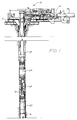
- FIGURE 1 is an elevation view of a subsea wellhead showing the use of the tubular connection of the present invention in a wellbore.
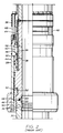
- FIGURE 2 is a quarter sectional view of a tubular connector of the prior art which has been used in a wellbore.
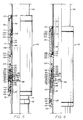
- FIGURE 3 is a quarter sectional view of the improved tubular connector of the present invention with the two tubular members spaced apart and ready for the connection to be made.
- FIGURE 4 is a quarter sectional view of the connector with the members commencing their interengagement.
- FIGURE 5 is another similar view of the connector with the members progressing and the latching fingers partially set.
- FIGURE 6 is another similar view of the connector in its connected and latched position.
- FIGURE 7 includes FIGURES 7A and 7B which are partial enlarged sectional views of the connector in its connected and latched position with FIGURE 7B showing the lower portion or extension of the connector shown in FIGURE 7A.
- In FIGURE 1
subsea well 10 is illustrated includingmudline support 12 on whichflowline connector 14 is supported,wellhead 16 withinwellbore 18 and connected throughconnector 20,master valve assembly 22,connector 24 andflowline extension spool 26 to the equipment onsupport 12 includingconnector 14.Connectors -
Prior art connector 28, shown in FIGURE 2, has been used in such installations.Connector 28 includes firsttubular member 30 having on its upper end internal taperedend sealing surface 32 andexternal engagement grooves 34, and secondtubular member 36 havingflange 38 on its upper end, and lower end internaltapered sealing surface 40 and externallatch foot groove 42 on its lower end,sleeve 44 surrounding secondtubular member 36 withlatching fingers 46 positioned between thelower interior surface 48 ofsleeve 44 and the lower exterior of secondtubular member 36. Latchingfingers 46 includebody 50,internal foot 52 on their upper end which projects intolatch foot groove 42 and internal lands orribs 54 which are spaced and sized for latching engagement withinexternal engagement grooves 34 in the upper end of firsttubular member 30. - Sleeve 44 is slidably mounted on the exterior of second
tubular member 36 and includesinternal rib 56 which projects into upperexternal recess 58 in secondtubular member 36. Withsuitable sealing recess 58 defines upper andlower piston chambers 60 and 62 to which hydraulic fluid is delivered alternately throughpassages sleeve 44 is moved downwardly onmember 36 and causes latchingfingers 46 to be cammed inwardly by the engagement of the internal surface of sleeve with the external surfaces offingers 46 into latching engagement withinengagement grooves 34 andlatch foot groove 42 to thereby complete the connection between the two tubular members.Guide rods 68 are secured to the upper end ofsleeve 28 and extend through suitable openings inflange 38. - As can be seen from the drawings and the foregoing description,
tubular connector 28 has its latching fingers and the interior of itssleeve 44 belowchambers 60 and 62 exposed to the environment surroundingtubular members prior art connector 28, difficulty can be encountered with the entry of the upper end of firsttubular member 30 within thelatching fingers 44. - Improved
connector 70 of the present invention is illustrated in the other figures.Connector 70 includes lowertubular member 72 having upper internaltapered sealing surface 74, upper external annular hub orrib 76 and lowerexternal rib 78 spaced belowupper rib 76 by a preselected distance as hereinafter explained.Connector 70 also includes uppertubular member 80,sleeve 82 andlatching fingers 84. - Upper
tubular member 80 includes lower internaltapered sealing surface 86 withseal ring 88 positioned thereon and retained by itsexternal rib 90 being engaged bysnap ring 92 ininternal groove 94 near the lower end oftubular member 80 as best shown in FIGURE 7.Tubular member 80 includes lower outer hub orrib 96,external setting rib 98 spaced aboverib 96, external release rib 100 spaced aboverib 98 and chamber definingexternal rib 102 spaced aboverib 100 all as shown and hereinafter described in detail.O ring 101 is positioned ingroove 103 on the outer surface or rib 102 for sealing against the interior surface ofsleeve 82.Sealing ring 104 is positioned in surrounding relationship to the exterior of uppertubular member 80 spaced aboverib 102 and includesinternal seal 106 andexternal seal 108 which seal respectively against the exterior surface oftubular member 80 and the interior ofsleeve 82.Lock ring 110 is threaded ontotubular member 80 as shown and provides the upper shoulder against which sealingring 104 abuts. -
Sleeve 82 surrounds the lower end of uppertubular member 80 with its lower end projecting beyond the lower end ofmember 80 asmember 80 is being lowered toward lowertubular member 72 as shown in FIGURE 3. Sleeve 82 includesinternal rib 112 withO ring 114 positioned ingroove 116 on the interior ofrib 112 and adapted to seal against exterior surface of uppertubular member 80 betweenrib 102 and sealingring 104.Sleeve 82 includes lowerinternal surface 118 which tapers inwardly and upwardly to receive the exterior oflatching fingers 84 in their unlatched position. Taperedshoulder 120 is positioned at the upper end ofsurface 118 and tapers inwardly and upwardly betweensurface 118 and upper internaltapered surface 122.Ring 124 is threaded onto the lower end ofsleeve 82 and includesinternal groove 126 in whichO ring 128 is positioned,upper surface 130 which tapers upwardly and inwardly to receive the lower ends oflatching fingers 84 andlower surface 132 which has a shallow taper to assist in the centering oftubular member 72 withinsleeve 82.Ring 134 is threaded onto the upper end ofsleeve 82 and includesinternal wiping seal 136 which engages the exterior oftubular member 80 abovering 110. - Latching
fingers 84 includebody 138 withouter surface 140 which tapers upwardly and inwardly, lowertapered surface 142 which engagessurface 130 ofring 124,internal groove 144 withtapered shoulders internal groove 150 which terminates inrib 152 withlower shoulder 154 andupper shoulder 156. Groove 144 is sized so thatshoulders shoulder 158 on the upper portion ofrib 96 on upper tubular member andshoulder 160 on the lower portion ofexternal rib 76 on lowertubular member 72 in clamping engagement to retain uppertubular member 80 and lowertubular member 72 in tight sealing engagement withseal ring 88. - Improved
tubular connector 70 is made up withsleeve 82 positioned around uppertubular member 80 as shown in FIGURE 3 withlower ring 124 extending below the lower end of uppertubular member 80. In this position the unit is lowered into position aligned with and approaching the upper end of lowertubular member 72. Asring 124 reacheshub 76 of lowertubular member 72, itstapered surface 132 aids in centering lowertubular member 72 withinsleeve 82. Oncehub 76 enters the interior ofring 124 it is in a cylindrical path leading to its engaged and sealed position with respect to the lower end of uppertubular member 80 and sealingring 88. This cylindrical path is formed by the interior ofring 124 and the interior of the lower portion oflatching fingers 84 which extend upward into surrounding relationship tohub 96 on uppertubular member 80. - Once engagement of
hub 76 withhub 96 andseal ring 88 is achieved as shown in FIGURE 4, pressure is conducted throughpassage 162 in uppertubular member 80 intosetting chamber 164 betweensealing ring 104 andinternal rib 112 onsleeve 82 andventing passage 166 andrelease chamber 168. This pressure causessleeve 82 to move downwardly carryinglatching fingers 84 in their position withinsurface 118. At the point as shown in FIGURE 5,lower shoulder 154 onrib 152 has engaged the upper surface ofrib 98 and further downward movement of latchingfingers 84 has been prevented. The continued downward movement ofsleeve 82 responsive to the pressure insetting chamber 164 has caused latchingfingers 84 to be forced upwardly over taperedshoulder 120 into engagement withsurface 122 as shown. The taper ofsurface 122cams latching fingers 84 inwardly so thathubs internal groove 144 of latchingfingers 84. The camming action of the further movement ofsleeve 82causes shoulders shoulders hubs tubular members seal ring 88 fitting in tight metal-to-metal sealing engagement withsurfaces - It should be noted from the drawings that in such latched positon,
O ring 128 on the interior ofring 124 is positioned in sealing engagement with the exterior surface ofrib 78 and seal 136 seals against the exterior oftubular member 82 to isolate latchingfingers 84 and the interior ofsleeve 82 surroundingtubular member release chambers tubular connector 70. - Release of
tubular connector 70 from its latched position is accomplished by venting hydraulic pressure from settingchamber 164 throughpassage 162 and delivering hydraulic pressure throughpassage 166 intorelease chamber 168. The pressure urgessleeve 82 upwardly and this movement ofsleeve 82 moves surface 122 from its camming engagement with the exterior of latchingfingers 84. The engagement of thelower end surface 142 of latchingfingers 84 onsurface 130 ofring 124 and the engagement ofupper shoulder 156 onrib 152 with the lower surface ofrib 100 occurs as the movement ofsleeve 82 stops. This allowssleeve 82 to stop its movement at a position with its rib 112 a short distance below sealingring 104 as shown in FIGURE 3.
Claims (7)
- A tubular connector comprising
a first tubular member (72) and a second tubular member (80), a sleeve (82) slidably mounted around the exterior of the first tubular member, and a plurality of latching fingers (84) carried within the sleeve, each latching finger having an internal profile (144) which can be moved into engagement with an exterior profile (76, 96) on the tubular members to latch them together when the sleeve is moved axially to a latching position, said sleeve having a surface which engages said latching fingers when they are in their restrained position and urges them to a position in which the profiles interengage, at least a portion of said sleeve (82) being spaced from one (80) of the tubular members to form a pressure chamber, and a port (162) extending through said one tubular member (80) into said pressure chamber (164) for supplying fluid pressure to said chamber to effect movement of said sleeve, means (98, 154) provided for restraining the axial movement of the latching fingers (84) when said profile is in alignment with the exterior profile of the tubular members characterised in that the latching fingers (84) are moveable with the sleeve during initial axial movement thereof, the arrangement is such that when fluid pressure is supplied to said chamber (164), the sleeve (82) and latching fingers (84) initially move together axially until the latching fingers are retrained by said restraining means (98, 154) following which further axial movement of said sleeve (82) causes the latching fingers (84) to move radially inwardly so that said profiles (144, 76, 96) interengage, the sleeve (82) in its latching position extending beyond the end of the latching fingers and including means (128) sealing between the interior of the sleeve and the exterior of the other (72) of the tubular members beyond the end of the latching fingers, and means (136) sealing between the interior of the sleeve and the exterior of said one of the tubular members (80). - A tubular connector according to claim 1 wherein said sleeve (82) has an internal cam surface (122) which coacts with a cam surface (140) on the exterior of the latching fingers (84) to effect said radially inwardly movement.
- A tubular connector according to claim 1 or claim 2, wherein said restraining means includes
shoulder means (154) on said latching fingers (84), and
shoulder means (98) on the exterior of said one of the tubular members and positioned to restrain said latching fingres (84) surrounding the ends of the tubular members in position for clamping engagement of the tubular members. - A tubular connector according to any preceding claim, wherein the exterior profiles (76, 96) of the tubular members include
hubs and
said latching fingers (84) engage opposite shoulders on the hubs of said tubular members to clamp the tubular members into tight engagement. - A tubular connector according to any preceding claim, including metal sealing means (88) for sealing between the interior surface at the connecting ends of the tubular members (72, 80).
- A tubular connector according to any preceding claim, wherein said pressure chamber (164) includes
means between the sleeve (82) and said one of the tubular members (80) defining a setting chamber (164) and a release chamber (168), and
means (162, 166) including said port (162) for delivering fluid pressure to and venting fluid pressure from said chambers. - A tubular connector according to any preceding claim, wherein the lower end (132) of said sleeve (82) is tapered downwardly and outwardly to guide said sleeve in its movement over said other tubular member (72).
Applications Claiming Priority (2)
| Application Number | Priority Date | Filing Date | Title |
|---|---|---|---|
| US94604186A | 1986-12-24 | 1986-12-24 | |
| US946041 | 1986-12-24 |
Publications (3)
| Publication Number | Publication Date |
|---|---|
| EP0272770A2 EP0272770A2 (en) | 1988-06-29 |
| EP0272770A3 EP0272770A3 (en) | 1989-06-28 |
| EP0272770B1 true EP0272770B1 (en) | 1994-07-27 |
Family
ID=25483868
Family Applications (1)
| Application Number | Title | Priority Date | Filing Date |
|---|---|---|---|
| EP87307097A Expired - Lifetime EP0272770B1 (en) | 1986-12-24 | 1987-08-11 | Tubular connector |
Country Status (7)
| Country | Link |
|---|---|
| US (1) | US4844511A (en) |
| EP (1) | EP0272770B1 (en) |
| JP (1) | JPS63167892A (en) |
| BR (1) | BR8704793A (en) |
| CA (1) | CA1309120C (en) |
| DE (1) | DE3750289T2 (en) |
| NO (1) | NO177158C (en) |
Families Citing this family (10)
| Publication number | Priority date | Publication date | Assignee | Title |
|---|---|---|---|---|
| US5924491A (en) * | 1997-07-03 | 1999-07-20 | Baker Hughes Incorporated | Thru-tubing anchor seal assembly and/or packer release devices |
| US6106024A (en) * | 1998-06-04 | 2000-08-22 | Cooper Cameron Corporation | Riser joint and apparatus for its assembly |
| US6554324B1 (en) * | 2000-10-31 | 2003-04-29 | Cooper Cameron Corporation | Apparatus and method for connecting tubular members |
| US6571879B1 (en) * | 2000-11-08 | 2003-06-03 | Baker Hughes Incorporated | Surface-actuated release tool for submersible pump assemblies |
| WO2003012242A1 (en) * | 2001-07-30 | 2003-02-13 | Smith International, Inc. | Downhole motor lock-up tool |
| US8096711B2 (en) * | 2007-12-21 | 2012-01-17 | Beauchamp Jim | Seal cleaning and lubricating bearing assembly for a rotating flow diverter |
| EP2742204B1 (en) | 2011-08-08 | 2022-10-19 | National Oilwell Varco, L.P. | Method and apparatus for connecting tubulars of a wellsite |
| BR112015006258B1 (en) | 2012-09-24 | 2021-06-01 | National Oilwell Varco, L.P. | SHUTTER UNIT FOR SEALING AROUND A SUBSEA ASCENDING PIPE, TELESCOPIC UNIT TO OPERACTLY CONNECT A SURFACE END OF A SUBSEA ASCENDING PIPE TO A PLATFORM, AND METHOD OF FORMATIONING A SEALING AROUND AN ASCENDING SEA TUBE |
| US9022125B2 (en) | 2012-11-30 | 2015-05-05 | National Oilwell Varco, L.P. | Marine riser with side tension members |
| US10329864B2 (en) * | 2016-12-28 | 2019-06-25 | Cameron International Corporation | Connector assembly for a mineral extraction system |
Family Cites Families (16)
| Publication number | Priority date | Publication date | Assignee | Title |
|---|---|---|---|---|
| US3239248A (en) * | 1962-01-18 | 1966-03-08 | Cameron Iron Works Inc | Apparatus for drilling and completing a well |
| US3241864A (en) * | 1962-10-29 | 1966-03-22 | Shaffer Tool Works | Automatic connector |
| US3353595A (en) * | 1964-05-22 | 1967-11-21 | Cameron Iron Works Inc | Underwater well completions |
| US3321217A (en) * | 1965-08-02 | 1967-05-23 | Ventura Tool Company | Coupling apparatus for well heads and the like |
| US3333870A (en) * | 1965-12-30 | 1967-08-01 | Regan Forge & Eng Co | Marine conductor coupling with double seal construction |
| US3608932A (en) * | 1970-02-18 | 1971-09-28 | Cicero C Brown | Powered coupling device |
| US3842914A (en) * | 1973-05-14 | 1974-10-22 | Hydril Co | Safety joint method and apparatus |
| US3918485A (en) * | 1973-09-18 | 1975-11-11 | Exxon Production Research Co | Multiport subsea connector |
| US4073511A (en) * | 1976-07-22 | 1978-02-14 | Haas Billie G | Coupling assembly for submarine casing sections |
| US4232888A (en) * | 1978-06-19 | 1980-11-11 | Baker International Corporation | Wireline releasable seal connector for wellpipe strings |
| US4526406A (en) * | 1981-07-16 | 1985-07-02 | Nelson Norman A | Wellhead connector |
| US4456070A (en) * | 1982-07-26 | 1984-06-26 | Hughes Tool Company | Tieback connection method and apparatus |
| US4496172A (en) * | 1982-11-02 | 1985-01-29 | Dril-Quip, Inc. | Subsea wellhead connectors |
| CA1224715A (en) * | 1983-02-18 | 1987-07-28 | Peter R. Gibb | Apparatus and method for connecting subsea production equipment to a floating facility |
| FR2552201B1 (en) * | 1983-09-15 | 1985-11-15 | Elf Aquitaine | DEVICE FOR CONNECTING AND DISCONNECTING A MOBILE TUBULAR CONDUIT WITHIN A FIXED TUBULAR CONDUIT |
| US4667986A (en) * | 1984-10-22 | 1987-05-26 | Otis Engineering Corporation | Wellhead connector |
-
1987
- 1987-07-28 CA CA000543110A patent/CA1309120C/en not_active Expired - Lifetime
- 1987-08-11 DE DE3750289T patent/DE3750289T2/en not_active Expired - Fee Related
- 1987-08-11 EP EP87307097A patent/EP0272770B1/en not_active Expired - Lifetime
- 1987-08-26 JP JP62212638A patent/JPS63167892A/en active Pending
- 1987-09-17 BR BR8704793A patent/BR8704793A/en not_active IP Right Cessation
- 1987-09-23 NO NO873987A patent/NO177158C/en unknown
-
1988
- 1988-08-04 US US07/228,754 patent/US4844511A/en not_active Expired - Fee Related
Also Published As
| Publication number | Publication date |
|---|---|
| NO177158B (en) | 1995-04-18 |
| JPS63167892A (en) | 1988-07-11 |
| BR8704793A (en) | 1988-07-19 |
| NO873987D0 (en) | 1987-09-23 |
| EP0272770A2 (en) | 1988-06-29 |
| CA1309120C (en) | 1992-10-20 |
| DE3750289D1 (en) | 1994-09-01 |
| US4844511A (en) | 1989-07-04 |
| DE3750289T2 (en) | 1994-12-08 |
| EP0272770A3 (en) | 1989-06-28 |
| NO873987L (en) | 1988-06-27 |
| NO177158C (en) | 1995-08-09 |
Similar Documents
| Publication | Publication Date | Title |
|---|---|---|
| EP0670413B1 (en) | Cement head quick connector | |
| EP0158455B1 (en) | Tubular connector | |
| EP3042031B1 (en) | Running tool | |
| US4405016A (en) | Underwater Christmas tree cap and lockdown apparatus | |
| EP0250072B1 (en) | Collet connector | |
| EP0579393B1 (en) | Sealing method and apparatus for wellheads | |
| US5259459A (en) | Subsea wellhead tieback connector | |
| US4667986A (en) | Wellhead connector | |
| US4479539A (en) | Downhole lock system | |
| US5433274A (en) | Hydraulic connector | |
| EP0343298B1 (en) | Running tool | |
| GB2296301A (en) | Lateral fluid or electrical coupling | |
| CA1200198A (en) | Flowline connector | |
| NO20150802A1 (en) | Closed-loop hydraulic running tool | |
| US4844511A (en) | Tubular connector | |
| US5299642A (en) | Subsea wellhead tieback connector | |
| EP0338154B1 (en) | Submerged actuator | |
| EP3234304A1 (en) | Hydraulic lockdown | |
| EP0509156B1 (en) | Sealing assembly | |
| US20230407720A1 (en) | Hydraulic lock apparatus | |
| US4657077A (en) | Locking production seal assembly | |
| EP3198109B1 (en) | Internal tieback with outer diameter sealing capability | |
| CA1182041A (en) | Well tool | |
| WO2019169061A1 (en) | Improved inner drilling riser tie-back internal connector | |
| CN111852368A (en) | Setting device and pipe string comprising same |
Legal Events
| Date | Code | Title | Description |
|---|---|---|---|
| PUAI | Public reference made under article 153(3) epc to a published international application that has entered the european phase |
Free format text: ORIGINAL CODE: 0009012 |
|
| AK | Designated contracting states |
Kind code of ref document: A2 Designated state(s): DE FR GB NL SE |
|
| PUAL | Search report despatched |
Free format text: ORIGINAL CODE: 0009013 |
|
| AK | Designated contracting states |
Kind code of ref document: A3 Designated state(s): DE FR GB NL SE |
|
| 17P | Request for examination filed |
Effective date: 19891204 |
|
| RAP1 | Party data changed (applicant data changed or rights of an application transferred) |
Owner name: COOPER INDUSTRIES,INC. |
|
| RAP1 | Party data changed (applicant data changed or rights of an application transferred) |
Owner name: COOPER INDUSTRIES INC. |
|
| 17Q | First examination report despatched |
Effective date: 19910614 |
|
| GRAA | (expected) grant |
Free format text: ORIGINAL CODE: 0009210 |
|
| AK | Designated contracting states |
Kind code of ref document: B1 Designated state(s): DE FR GB NL SE |
|
| PG25 | Lapsed in a contracting state [announced via postgrant information from national office to epo] |
Ref country code: NL Effective date: 19940727 |
|
| REF | Corresponds to: |
Ref document number: 3750289 Country of ref document: DE Date of ref document: 19940901 |
|
| ET | Fr: translation filed | ||
| PG25 | Lapsed in a contracting state [announced via postgrant information from national office to epo] |
Ref country code: SE Effective date: 19941027 |
|
| NLV1 | Nl: lapsed or annulled due to failure to fulfill the requirements of art. 29p and 29m of the patents act | ||
| PLBE | No opposition filed within time limit |
Free format text: ORIGINAL CODE: 0009261 |
|
| STAA | Information on the status of an ep patent application or granted ep patent |
Free format text: STATUS: NO OPPOSITION FILED WITHIN TIME LIMIT |
|
| PGFP | Annual fee paid to national office [announced via postgrant information from national office to epo] |
Ref country code: GB Payment date: 19950711 Year of fee payment: 9 |
|
| 26N | No opposition filed | ||
| PGFP | Annual fee paid to national office [announced via postgrant information from national office to epo] |
Ref country code: FR Payment date: 19950814 Year of fee payment: 9 |
|
| PGFP | Annual fee paid to national office [announced via postgrant information from national office to epo] |
Ref country code: DE Payment date: 19950828 Year of fee payment: 9 |
|
| REG | Reference to a national code |
Ref country code: GB Ref legal event code: 732E |
|
| PG25 | Lapsed in a contracting state [announced via postgrant information from national office to epo] |
Ref country code: GB Effective date: 19960811 |
|
| GBPC | Gb: european patent ceased through non-payment of renewal fee |
Effective date: 19960811 |
|
| PG25 | Lapsed in a contracting state [announced via postgrant information from national office to epo] |
Ref country code: FR Effective date: 19970430 |
|
| PG25 | Lapsed in a contracting state [announced via postgrant information from national office to epo] |
Ref country code: DE Effective date: 19970501 |
|
| REG | Reference to a national code |
Ref country code: FR Ref legal event code: ST |