EP0271807A2 - Fault-tolerant computing system and method for detecting, localising and eliminating failing units in such a system - Google Patents
Fault-tolerant computing system and method for detecting, localising and eliminating failing units in such a system Download PDFInfo
- Publication number
- EP0271807A2 EP0271807A2 EP87118149A EP87118149A EP0271807A2 EP 0271807 A2 EP0271807 A2 EP 0271807A2 EP 87118149 A EP87118149 A EP 87118149A EP 87118149 A EP87118149 A EP 87118149A EP 0271807 A2 EP0271807 A2 EP 0271807A2
- Authority
- EP
- European Patent Office
- Prior art keywords
- processors
- results
- fault
- faulty
- test
- Prior art date
- Legal status (The legal status is an assumption and is not a legal conclusion. Google has not performed a legal analysis and makes no representation as to the accuracy of the status listed.)
- Withdrawn
Links
Images
Classifications
-
- G—PHYSICS
- G06—COMPUTING; CALCULATING OR COUNTING
- G06F—ELECTRIC DIGITAL DATA PROCESSING
- G06F11/00—Error detection; Error correction; Monitoring
- G06F11/07—Responding to the occurrence of a fault, e.g. fault tolerance
- G06F11/16—Error detection or correction of the data by redundancy in hardware
- G06F11/18—Error detection or correction of the data by redundancy in hardware using passive fault-masking of the redundant circuits
- G06F11/182—Error detection or correction of the data by redundancy in hardware using passive fault-masking of the redundant circuits based on mutual exchange of the output between redundant processing components
-
- G—PHYSICS
- G06—COMPUTING; CALCULATING OR COUNTING
- G06F—ELECTRIC DIGITAL DATA PROCESSING
- G06F11/00—Error detection; Error correction; Monitoring
- G06F11/07—Responding to the occurrence of a fault, e.g. fault tolerance
- G06F11/14—Error detection or correction of the data by redundancy in operation
- G06F11/1497—Details of time redundant execution on a single processing unit
-
- G—PHYSICS
- G06—COMPUTING; CALCULATING OR COUNTING
- G06F—ELECTRIC DIGITAL DATA PROCESSING
- G06F11/00—Error detection; Error correction; Monitoring
- G06F11/07—Responding to the occurrence of a fault, e.g. fault tolerance
- G06F11/16—Error detection or correction of the data by redundancy in hardware
- G06F11/1608—Error detection by comparing the output signals of redundant hardware
- G06F11/1625—Error detection by comparing the output signals of redundant hardware in communications, e.g. transmission, interfaces
-
- G—PHYSICS
- G06—COMPUTING; CALCULATING OR COUNTING
- G06F—ELECTRIC DIGITAL DATA PROCESSING
- G06F11/00—Error detection; Error correction; Monitoring
- G06F11/07—Responding to the occurrence of a fault, e.g. fault tolerance
- G06F11/16—Error detection or correction of the data by redundancy in hardware
- G06F11/1629—Error detection by comparing the output of redundant processing systems
- G06F11/1633—Error detection by comparing the output of redundant processing systems using mutual exchange of the output between the redundant processing components
-
- G—PHYSICS
- G06—COMPUTING; CALCULATING OR COUNTING
- G06F—ELECTRIC DIGITAL DATA PROCESSING
- G06F11/00—Error detection; Error correction; Monitoring
- G06F11/07—Responding to the occurrence of a fault, e.g. fault tolerance
- G06F11/16—Error detection or correction of the data by redundancy in hardware
- G06F11/1629—Error detection by comparing the output of redundant processing systems
- G06F11/1641—Error detection by comparing the output of redundant processing systems where the comparison is not performed by the redundant processing components
- G06F11/1645—Error detection by comparing the output of redundant processing systems where the comparison is not performed by the redundant processing components and the comparison itself uses redundant hardware
-
- G—PHYSICS
- G06—COMPUTING; CALCULATING OR COUNTING
- G06F—ELECTRIC DIGITAL DATA PROCESSING
- G06F11/00—Error detection; Error correction; Monitoring
- G06F11/07—Responding to the occurrence of a fault, e.g. fault tolerance
- G06F11/16—Error detection or correction of the data by redundancy in hardware
- G06F11/1629—Error detection by comparing the output of redundant processing systems
- G06F11/165—Error detection by comparing the output of redundant processing systems with continued operation after detection of the error
-
- G—PHYSICS
- G06—COMPUTING; CALCULATING OR COUNTING
- G06F—ELECTRIC DIGITAL DATA PROCESSING
- G06F11/00—Error detection; Error correction; Monitoring
- G06F11/07—Responding to the occurrence of a fault, e.g. fault tolerance
- G06F11/16—Error detection or correction of the data by redundancy in hardware
- G06F11/18—Error detection or correction of the data by redundancy in hardware using passive fault-masking of the redundant circuits
- G06F11/181—Eliminating the failing redundant component
Definitions
- the invention relates to a method for recognizing, locating and eliminating faulty units in a computer system according to the preamble of claim 1 and to a fault-tolerant computer system for performing the method.
- Fault-tolerant systems continue to control and regulate a technical process even if part of the automation system becomes defective. To do this, an occurring error must be detected, localized and finally eliminated by separating the faulty part of the system.
- Systems in which a decision about the correctness of the results from three or four processors working in parallel is made using a 2-out or 3-out majority decision are generally known.
- a fault-tolerant parallel computer system with three or four processors working in parallel is known from European application 01 43 125. The disadvantage of such systems is the high effort required.
- the present invention is based on the object of specifying a fast-working method for recognizing, locating and eliminating practically all simple errors in a computer system with two computers coupled at the output.
- a fault-tolerant computing system for performing the method is to be specified.
- a fault in a subsystem is not only recognized but also localized without the aid of a third or fourth processor and the source of the fault is quickly eliminated by isolating the faulty part.
- the system exhibits fail-safe behavior during the short time between error detection and elimination (peak time).
- the mutual test of the processors working in parallel or the determination of which of the processors is intact is still possible even if one of the processors has failed completely is, or provides any undefined results.
- the proposed non-reactive coupling of the system components enables the addition or replacement of components during operation. Further advantages result from the subclaims and the following description of an exemplary embodiment which is shown in the drawing.
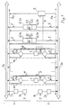
- FIG. 1 shows the architecture of a fault-tolerant computing system according to the invention.
- Two identical subsystems a, b are shown in a non-reactive, symmetrical system structure.
- the overall system therefore has simple redundancy.
- the system contains two input modules 1a, 1b which work independently of one another and to which identical input data E are supplied.
- the output of the input modules 1a, 1b is connected to each bus system 3a, 3b without feedback via first coupling elements 2a, 2b.
- a number 1 to n of microprocessor pairs M1 to Mn are connected to the bus systems 3a, 3b.
- Such a pair of microprocessors M1 to Mn each contain two processors P1a and P1b, or P2a and P2b etc., second coupling elements 4, each of which connects the two processors, for example P1a and P1b, without interference, and two separating devices 5, each via one of the processors , for example P1a is connected to the associated bus system, for example P3a of the respective subsystem, for example a.
- Output modules 6.1a, 6.1b and 6.2a, 6.2b are also provided, each output module, for example 6.1a, being connected to a bus system, for example 3a, via a disconnection device 5, also referred to as an isolation switch, and two output modules, for example 6.1a, 6.1b, each having no reaction a comparator 7.1, 7.2, for example 7.1, which outputs an output signal A1, A2, for example A1.
- the comparators 7.1, 7.2 additionally generate an evaluation signal B1 or B2, which has two non-reactive Auxiliary buses Xa, Xb the processors Pna (P1a, P2a etc.) bw. Pnb (P1b, P2b, etc.) is supplied.
- the auxiliary buses Xa, Xb are preferably designed as serial buses.
- Input data E arrive via the input modules 1a, 2a and the bus systems 3a, 3b e.g. to the microprocessor pair M1.
- the processors e.g. P1a, P1b of the microprocessor pair M1 work with the same input data E in synchronism with the algorithm.
- the results of the processors P1a, P1b are sent via the bus systems 3a, 3b to the output modules 6.1a, 6.2a and 6.1b, 6.2b.
- the comparator, e.g. 7.1 compares the results from the two subsystems a, b in the output modules 6.1a, 6.1b.
- the results are identical and the output signal A1 is switched through.
- the comparator e.g. 7.1 an evaluation signal B1, which informs the processors Pna and Pnb of the comparator result via the auxiliary buses Xa and Xb.
- the second comparator 7.2 carries out a comparison of the results from the two subsystems a, b that are present in the output modules 6.2a, 6.2b and outputs an output signal A2 and the auxiliary signal B2.
- the output signals A1, A2 and the output signals of any further output modules can be checked by additional monitoring devices, not shown.
- the computer system becomes a fault-tolerant system thanks to its facilities for fault detection, fault localization, fault reaction, fault messages with fault location messages and fault rectification. System status monitoring is also provided.
- a sum error detection is provided for error detection.
- the comparators 7.1, 7.2 respond and prevent incorrect output.
- the fault is localized by isolating it according to an exclusion procedure with autonomous individual tests.
- Basic system tests are carried out in a test stage. This includes cyclical hardware tests in the background, which relate to the comparator hardware and the bus systems 3a, 3b, including the interface devices and all separation devices 5.
- the processor pairs are tested if evaluation signals B1 or B2 are negative, ie if the results of subsystems a, b differ.
- a software comparator is provided in each processor P, which compares the intermediate results of the algorithm steps of two processors belonging to a microprocessor pair, for example M1, for example P1a, P1b.
- the processors P of a pair of microprocessors M operate synchronously. The results of two successive algorithm steps are stored in both processors, for example P1a, P1b.
- step N + 1 is a test step to determine which of the two processors, for example P1a, P1b, has worked incorrectly.
- the useful algorithm of processing step N-1 is used as the test algorithm, which has led to the same intermediate result for both processors and is stored.
- test step N + 1 the now defective processor will no longer be able to deliver the correct result.
- the one of the two processors of a pair Pna, b whose self-test succeeds by comparing the N-1 user algorithm step with the first test step after the error message (this is now the N-1 user algorithm again as a test algorithm) and who reports the test results incorrectly or inconsistently receives its partner via the coupling element 4, actively separates this partner from one of the system buses 3a or 3b via separate control lines 10 and the isolation switches 5.
- the faulty processor is thus recognized and has been eliminated from the system as a source of interference.
- the result of this second test stage is communicated to the comparators 7.1 and 7.2, which learn that they can leave their fail-safe state and are only supplied by one subsystem until the defective processor module has been replaced.
- a test of the last untested hardware remainder of the input modules 1a, 1b and output modules 6.1a takes place , 6.1b, 6.2a, 6.2b by tentatively disconnecting one of these modules by switching off the transceiver with the separator 5 in the interfaces of these modules to the bus system 3a, 3b.
- the defective subsystem or the defective assembly determined in the phase of fault localization is separated with the aid of the separation points 5.
- Comparator 7.1 blocked the output of a new result. This means that the last correct old value remains at the output as output signal A1, A2 until the faulty system unit has been determined and separated. During this time, which typically lasts a few milliseconds, the system exhibits fail-safe behavior. After that, the system continues to operate with undiminished performance but reduced redundancy as long as the defective part is not replaced.
- a continuous self-test of the processors P of a pair of microprocessors M can additionally be provided in the background mode, the processors P alternately testing one another.
- An error reporting device 8 is also provided in the overall system. This device detects all fault situations, partly via the auxiliary buses Xa, Xb and partly via direct signal lines 9 from system parts not directly connected to the bus 3a, 3b, e.g. Coupling elements 4.
- the faulty states include the response of the comparators 7.1, 7.2, results of the tests of transceivers in the interfaces to the bus systems 3a, 3b (transceiver tests), state of the separating devices 5 and the first coupling elements 2, results of the Tests of processors P1 to Pn and the synchronous state of the processors P in a microprocessor pair M.
Abstract
Description
Die Erfindung bezieht sich auf ein Verfahren zum Erkennen, Lokalisieren und Eliminieren von fehlerhaften Einheiten in einem Rechensystem nach dem Oberbegriff des Anspruchs 1 sowie auf ein fehlertolerantes Rechensystem zur Durchführung des Verfahrens.The invention relates to a method for recognizing, locating and eliminating faulty units in a computer system according to the preamble of claim 1 and to a fault-tolerant computer system for performing the method.
Besonders bei Anwendungen von Rechensystemen zur Automatisierung technischer Prozesse wird in zunehmendem Maße verlangt, daß Störungen in einer derartigen Datentverarbeitungsanlage erkannt werden und daß die Sicherheit und/oder die Verfügbarkeit nicht durch solche Störungen beeinträchtigt werden. Bezüglich der Reaktion auf detektierte Fehler wird unterschieden nach fail-safe-Verhalten und fehlertolerantem Verhalten. Bei sogenannten non-stop-Systemen wird außer dem fehlerhaften Verhalten zusätzlich verlangt, daß defekte Baugruppen entfernt bzw. intakte Baugruppen hinzugefügt werden können, ohne den laufenden Betrieb zu stören oder zu unterbrechen. Auch die Resynchronisation und Aktualisierung hinzugefügter Baugruppen muß im laufenden Nutzbetrieb erfolgen.Particularly in the case of applications of computer systems for the automation of technical processes, it is increasingly required that faults in such a data processing system are recognized and that the security and / or the availability are not impaired by such faults. With regard to the reaction to detected errors, a distinction is made between fail-safe behavior and fault-tolerant behavior. In so-called non-stop systems, in addition to the faulty behavior, it is additionally required that defective modules can be removed or intact modules can be added without disrupting or interrupting ongoing operation. The resynchronization and updating of added modules must also be carried out during normal operation.
Auf Gebieten der Sicherungstechnik, wie z.B. der Eisenbahnsignaltechnik wendet man das fail-safe-Prinzip an, wobei ohne Rücksicht auf die Verfügbarkeit der angeschlossene Prozeß in einen sicheren Zustand überführt wird. Solche Datenverarbeitungseinrichtungen mit reinem fail-safe-Verhalten sind z.B. aus den europäischen Anmeldung 01 56 388 und 01 48 995 bekannt.In the fields of security technology, e.g. Railway signaling technology uses the fail-safe principle, whereby the connected process is brought into a safe state regardless of the availability. Such data processing devices with pure fail-safe behavior are e.g. known from European application 01 56 388 and 01 48 995.
Fehlertolerierente Systeme führen die Steuerung und Regelung eines technischen Prozesses auch dann fort, wenn ein Teil des Automatisierungssystems defekt wird. Dazu muß ein auftretender Fehler detektiert, lokalisiert und schließlich eliminiert werden, indem der fehlerhafte Anlagenteil abgetrennt wird. Allgemein bekannt sind Systeme, bei denen über eine 2aus3- oder 3aus4-Mehrheitsentscheidung eine Entscheidung über die Richtigkeit der Ergebnisse aus drei bzw. vier parallel arbeitenden Prozessoren gefällt wird. Aus der europäischen Anmeldung 01 43 125 ist beispielsweise ein fehlertolerantes Parallelrechnersystem mit drei bzw. vier parallel arbeitenden Prozessoren bekannt. Nachteilig ist bei solchen Systemen der erforderliche hohe Aufwand.Fault-tolerant systems continue to control and regulate a technical process even if part of the automation system becomes defective. To do this, an occurring error must be detected, localized and finally eliminated by separating the faulty part of the system. Systems in which a decision about the correctness of the results from three or four processors working in parallel is made using a 2-out or 3-out majority decision are generally known. For example, a fault-tolerant parallel computer system with three or four processors working in parallel is known from European application 01 43 125. The disadvantage of such systems is the high effort required.
Es sind auch solche Systeme bekannt, bei denen zwei Rechner parallel arbeiten. Das dabei auftretende Problem, bei unterschiedlichen Ergebnissen aus den beiden Rechnern zu entscheiden, welches Ergebnis richtig ist bzw. welcher Rechner defekt ist, ist z.B. angesprochen in NTG-Fachberichte 92, Seite 7 bis 29, insbesondere Seite 16, und es sind dort Möglichkeiten zur Erkennung von fehlerhaften Einheiten angegeben. Zu diesen Möglichkeiten zählt der Selbsttest mit Hilfe von Selbsttestprogrammen. Voraussetzung ist dabei, daß der Rechner noch so weit intakt ist, daß er einen solchen Selbsttest durchführen kann. Mit Hilfe solcher Testprogramme kann ein Rechner auch seinen Nachbarn überprüfen, wobei auch dies bei nur zwei Rechnern voraussetzt, daß eine Mindestfunktionsfähigkeit beider Rechner gegeben ist. Beim Selbsttest besteht auch das Problem, daß entweder eine lückenhafte Fehleraufdeckung gegeben ist, oder eine sehr lange Testzeit erforderlich ist. Ähnliche Probleme sind aus der Fertigungskontrolle bekannt. Bei Duplex-Fehlertoleranz steht während des langwierigen Selbsttests keine Ein-Ausgabe-Funktion zur Verfügung.Systems are also known in which two computers work in parallel. The problem that arises in the case of different results from the two computers to decide which result is correct or which computer is defective is addressed, for example, in NTG technical reports 92, pages 7 to 29, in
Davon ausgehend liegt der vorliegenden Erfindung die Aufgabe zugrunde, ein schnell arbeitendes Verfahren zum Erkennen, Lokalisieren und Eliminieren von praktisch allen Einfach-Fehlern in einem Rechensystem mit zwei am Ausgang gekoppelten Rechnern anzugeben. Außerdem soll ein fehlertolerantes Rechensystem zur Durchführung des Verfahrens angegeben werden.Proceeding from this, the present invention is based on the object of specifying a fast-working method for recognizing, locating and eliminating practically all simple errors in a computer system with two computers coupled at the output. In addition, a fault-tolerant computing system for performing the method is to be specified.
Diese Aufgabe wird durch ein Verfahren nach Anspruch 1 sowie ein Rechensystem nach dem Anspruch 4 gelöst. Vorteilhafte Ausgestaltungen sind in Unteransprüchen angegeben.This object is achieved by a method according to claim 1 and a computing system according to
Vorteile des Verfahrens sind insbesondere darin zu sehen, daß eine Störung in einem Teilsystem ohne zu Hilfenahme eines dritten oder vierten Prozessors nicht nur erkannt, sondern auch lokalisiert und die Störungsquelle schnell durch Isolation des fehlerhaften Teils eliminiert wird. Während der kurzen Zeit zwischen der Fehlererkennung und Beseitigung (Stoßzeit) weist das System fail-safe-Verhalten auf. Der gegenseitige Test der parallel arbeitenden Prozessoren bzw. die Feststellung welcher der Prozessoren intakt ist, ist auch dann noch möglich, wenn einer der Prozessoren ganz ausgefallen ist, bzw. beliebig undefinierte Ergebnisse liefert. Die vorgesehene rückwirkungsfreie Kopplung der Systemkomponenten ermöglicht ein Hinzufügen oder den austausch von Komponenten während des Betriebs. Weitere Vorteile ergeben sich aus den Unteransprüchen und der nachstehenden Beschreibung eines Ausführungsbeispiels, das in der Zeichnung dargestellt ist.Advantages of the method can be seen in particular in the fact that a fault in a subsystem is not only recognized but also localized without the aid of a third or fourth processor and the source of the fault is quickly eliminated by isolating the faulty part. The system exhibits fail-safe behavior during the short time between error detection and elimination (peak time). The mutual test of the processors working in parallel or the determination of which of the processors is intact is still possible even if one of the processors has failed completely is, or provides any undefined results. The proposed non-reactive coupling of the system components enables the addition or replacement of components during operation. Further advantages result from the subclaims and the following description of an exemplary embodiment which is shown in the drawing.
Fig. 1 zeigt die Architektur eines erfindungsgemäßen fehlertoleranten Rechensystems. Dabei sind zwei identische Teilsysteme a, b dargestellt, in einem rückwirkungsfreien, symmetrischen Systemaufbau. Das Gesamtsystem hat also einfache Redundanz. Das System enthält zwei voneinander unabhängig arbeitende Eingabebaugruppen 1a, 1b, denen identische Eingabedaten E zugeführt sind. Der Ausgang der Eingabebaugruppen 1a, 1b ist über erste Koppelglieder 2a, 2b rückwirkungsfrei mit je einem Bussystem 3a, 3b verbunden. An die Bussysteme 3a, 3b sind eine Anzahl 1 bis n von Mikroprozessorpaaren M1 bis Mn angeschlossen. Ein solches Mikroprozessorpaar M1 bis Mn enthält jeweils zwei Prozessoren P1a und P1b, bzw. P2a und P2b usw., zweite Koppelglieder 4, die jeweils die zwei Prozessoren, z.B. P1a und P1b miteinander rückwirkungsfrei verbinden, sowie zwei Trenneinrichtungen 5 über die jeweils einer der Prozessoren, z.B. P1a mit dem zugehörigen Bussystem, z.B. P3a des jeweiligen Teilsystems z.B. a verbunden ist. Weiterhin sind Ausgabebaugruppen 6.1a, 6.1b bzw. 6.2a, 6.2b vorgesehen, wobei jeder Ausgabebaustein z.B. 6.1a über eine auch als Isolationsschalter bezeichnete Trenneinrichtung 5 mit einem Bussystem z.B. 3a verbunden ist und jeweils zwei Ausgabebausteine z.B. 6.1a, 6.1b rückwirkungsfrei mit einem Comparator 7.1, 7.2, z.B. 7.1, zusammengeschaltet sind, der ein Ausgangssignal A1, A2, z.B. A1 abgibt. Die Comparatoren 7.1, 7.2 erzeugen zusätzlich ein Bewertungssignal B1 bzw. B2, das über zwei rückwirkungsfreie Hilfsbusse Xa, Xb den Prozessoren Pna (P1a, P2a usw.) bw. Pnb (P1b, P2b usw.) zugeführt wird. Die Hilfsbusse Xa, Xb sind vorzugsweise als serielle Busse ausgeführt.1 shows the architecture of a fault-tolerant computing system according to the invention. Two identical subsystems a, b are shown in a non-reactive, symmetrical system structure. The overall system therefore has simple redundancy. The system contains two input modules 1a, 1b which work independently of one another and to which identical input data E are supplied. The output of the input modules 1a, 1b is connected to each
Nachstehend wird die Funktionsweise des in Fig. 1 dargestellten Rechensystems beschrieben. Eingangsdaten E gelangen über die Eingabebaugruppen 1a, 2a und die Bussysteme 3a, 3b z.B. zum Mikroprozessorpaar M1. Die Prozessoren z.B. P1a, P1b des Mikroprozessorpaares M1 arbeiten algorithmensynchron mit den gleichen Eingabedaten E. Die Ergebnisse der Prozessoren P1a, P1b werden über die Bussysteme 3a, 3b zu den Ausgabebausteinen 6.1a, 6.2a bzw. 6.1b, 6.2b gegeben. Der Comparator, z.B. 7.1 vergleicht die in den Ausgabebausteinen 6.1a, 6.1b anstehenden Ergebnisse aus den beiden Teilsystemen a, b. Im störungsfreien Betrieb sind die Ergebnisse identisch und es erfolgt eine Durchschaltung als Ausgangssignal A1. Zusätzlich erzeugt der Comparator, z.B. 7.1 ein Bewertungssignal B1, welches den Prozessoren Pna und Pnb das Comparatorergebnis über die Hilfsbusse Xa und Xb mitteilt. In gleicher Weise führt der zweite Comparator 7.2 einen Vergleich der Ergebnisse aus den beiden Teilsystemen a, b durch, die in den Ausgabebausteinen 6.2a, 6.2b anstehen und gibt ein Ausgangssignal A2 und das Hilfssignal B2 ab. Die Ausgangssignale A1, A2 und die Ausgangssignale eventuell weiterer Ausgabebausteine können durch zusätzliche, nicht dargestellte Überwachungseinrichtungen überprüft werden.The operation of the computing system shown in Fig. 1 is described below. Input data E arrive via the
Zum fehlertoleranten System wird das Rechensystem durch seine Einrichtungen zur Fehlerdetektion, Fehlerlokalisation, Fehlerreaktion, Fehlermeldung mit Fehlerortsmeldung und zur Fehlerbeseitigung. Außerdem ist eine Systemzustandsüberwachung vorgesehen.The computer system becomes a fault-tolerant system thanks to its facilities for fault detection, fault localization, fault reaction, fault messages with fault location messages and fault rectification. System status monitoring is also provided.
Zur Fehlerdetektion ist eine Summenfehlerdetektion vorgesehen. Bei Systemfehlern, gleichgültig welcher Art, sprechen die Comparatoren 7.1, 7.2 an und verhindern eine fehlerhafte Ausgabe.A sum error detection is provided for error detection. In the event of system errors of any kind, the comparators 7.1, 7.2 respond and prevent incorrect output.
Die Fehlerlokalisation erfolgt durch Eingrenzung nach einem Ausschlußverfahren mit autonomen Einzeltests. In einer Teststufe werden Grundsystemtests durchgeführt. Dazu gehören zyklische Hardware-Tests im Hintergrund, die sich auf die Comparator-Hardware und die Bussysteme 3a, 3b einschließlich der Schnittstelleneinrichtungen und aller Trenneinrichtungen 5 beziehen.The fault is localized by isolating it according to an exclusion procedure with autonomous individual tests. Basic system tests are carried out in a test stage. This includes cyclical hardware tests in the background, which relate to the comparator hardware and the
In einer zweiten Teststufe werden die Prozessorpaare, z.B. P1a, P1b getestet, falls Bewertungssignale B1 oder B2 negativ sind, d.h. wenn die Ergebnisse der Teilsysteme a, b voneinander abweichen. Dazu ist in jedem Prozessor P ein Software-Comparator vorgesehen, der Zwischenergebnisse der Algorithmenschritte zweier zu einem Mikroprozessorpaar, z.B. M1 gehörenden Prozessoren, z.B. P1a, P1b vergleicht. Wie bereits zuvor erwähnt, arbeiten die Prozessoren P eines Mikroprozessorpaares M algorithmensynchron. Die Ergebnisse zweier aufeinanderfolgender Algorithmenschritte werden jeweils in beiden Prozessoren, z.B. P1a, P1b gespeichert. Wenn ein Verarbeitungsschritt N erreicht ist, in dem fehlende Übereinstimmung der Ausgangssignale A1, A2 der Teilsysteme a, b erreicht ist, erfolgt als nächster Schritt N+1 ein Testschritt zur Feststellung welcher der beiden Prozessoren z.B. P1a, P1b fehlerhaft gearbeitet hat. Dabei ist als Test-Algorithmus der Nutz-Algorithmus des Verarbeitungsschritts N-1 verwendet, der noch bei beiden Prozessoren zum gleichen Zwischenergebnis geführt hat, und das gespeichert ist. Im Testschritt N+1 wird der inzwischen defekte Prozessor nicht mehr in der Lage sein, das richtige Ergebnis zu liefern. Durch Vergleich der Ergebnisse der Prozessoren z.B. P1a, P2a im Schritt N+1 mit dem Ergebnis aus dem Schritt N-1 kann somit vom Software-Comparator zumindest in demjenigen Prozessor, der noch vollständig in Ordnung ist, festgestellt werden, welcher Prozessor ein falsches Ergebnis liefert. Derjenige der beiden Prozessoren eines Paares Pna,b, dessen Selbsttest durch Vergleich des N-1 Nutzalgorithmusschrittes mit dem ersten Testschritt nach der Fehlermeldung (dies ist jetzt als Testalgorithmus wieder der N-1 Nutzalgorithmus) positiv gelingt und der eine falsche oder inkonsistente Meldung der Testergebnisse seines Partners über das Koppelglied 4 erhält, trennt diesen Partner aktiv über getrennte Steuerleitungen 10 und die Isolationsschalter 5 von einem der Systembusse 3a oder 3b ab. Der fehlerhafte Prozessor ist damit erkannt und als Störungsquelle aus dem System eliminiert worden. Das Ergebnis dieser zweiten Teststufe wird den Comparatoren 7.1 und 7.2 mitgeteilt, die dadurch erfahren, daß sie ihren fail-safe-Zustand verlassen können und bis zum erfolgten Wechsel des defekten Prozessormoduls nur noch von einem Teilsystem versorgt werden.In a second test stage, the processor pairs, for example P1a, P1b, are tested if evaluation signals B1 or B2 are negative, ie if the results of subsystems a, b differ. For this purpose, a software comparator is provided in each processor P, which compares the intermediate results of the algorithm steps of two processors belonging to a microprocessor pair, for example M1, for example P1a, P1b. As already mentioned before, the processors P of a pair of microprocessors M operate synchronously. The results of two successive algorithm steps are stored in both processors, for example P1a, P1b. If a processing step N is reached in which the output signals A1, A2 of the subsystems a, b do not match, the next step N + 1 is a test step to determine which of the two processors, for example P1a, P1b, has worked incorrectly. The useful algorithm of processing step N-1 is used as the test algorithm, which has led to the same intermediate result for both processors and is stored. In test step N + 1, the now defective processor will no longer be able to deliver the correct result. By comparing the results of the processors, for example P1a, P2a in step N + 1 with the result from step N-1, the software comparator can thus determine which processor is delivering a wrong result, at least in the processor that is still completely in order. The one of the two processors of a pair Pna, b, whose self-test succeeds by comparing the N-1 user algorithm step with the first test step after the error message (this is now the N-1 user algorithm again as a test algorithm) and who reports the test results incorrectly or inconsistently receives its partner via the
In einer dritten Teststufe erfolgt für den Fall, daß mit den Teststufen 1 und 2 kein fehlerhaftes Systemteil lokalisierbar war, und der Comparator 7.1, 7.2 trotzdem anspricht, ein Test des letzten noch nicht geprüften Hardware-Rests der Eingabebaugruppen 1a, 1b und Ausgabebausteine 6.1a, 6.1b, 6.2a, 6.2b durch versuchsweise Abtrennung jeweils einer dieser Baugruppen durch Abschalten der Sende-Empfangseinrichtung mit der Trenneinrichtung 5 in den Schnittstellen dieser Baugruppen zum Bussystem 3a, 3b.In a third test stage, in the event that no faulty system part could be localized with test stages 1 and 2, and the comparator 7.1, 7.2 still responds, a test of the last untested hardware remainder of the input modules 1a, 1b and output modules 6.1a takes place , 6.1b, 6.2a, 6.2b by tentatively disconnecting one of these modules by switching off the transceiver with the
Als Fehlerreaktion wird das in der Phase der Fehlerlokalisation ermittelte defekte Teilsystem bzw. die defekte Baugruppe mit Hilfe der Trennstellen 5 abgetrennt. Außerdem wurde bei Feststellung eines Fehlers im System vom Comparator 7.1, 7.2 die Ausgabe eines neuen Ergebnisses gesperrt. Das heißt, der letzte richtige Altwert bleibt am Ausgang als Ausgangssignal A1, A2 solange bestehen, bis die fehlerhafte Systemeinheit ermittelt und abgetrennt ist. Während dieser Zeit, die typisch einige Millisekunden dauert, weist das System also fail-safe-Verhalten auf. Danach arbeitet das System mit unverminderter Leistung, aber verminderter Redundanz weiter, solange das defekte Teil nicht ersetzt ist.As a fault reaction, the defective subsystem or the defective assembly determined in the phase of fault localization is separated with the aid of the separation points 5. In addition, when an error was found in the system from Comparator 7.1, 7.2 blocked the output of a new result. This means that the last correct old value remains at the output as output signal A1, A2 until the faulty system unit has been determined and separated. During this time, which typically lasts a few milliseconds, the system exhibits fail-safe behavior. After that, the system continues to operate with undiminished performance but reduced redundancy as long as the defective part is not replaced.
Nach einer vorteilhaften Ausgestaltung der Erfindung kann zusätzlich ein andauernder Selbsttest der Prozessoren P eines Mikroprozessorpaares M im Hintergrundbetrieb vorgesehen werden, wobei sich die Prozessoren P alternierend gegenseitig testen.According to an advantageous embodiment of the invention, a continuous self-test of the processors P of a pair of microprocessors M can additionally be provided in the background mode, the processors P alternately testing one another.
Im Gesamtsystem ist außerdem eine Fehlermeldeeinrichtung 8 vorgesehen. Diese Einrichtung erfaßt alle Fehlersituationen, die teils über die Hilfsbusse Xa, Xb und teils über direkte Meldeleitungen 9 aus nicht direkt am Bus 3a, 3b angeschlossenen Systemteilen, z.B. Koppelgliedern 4. Zu den fehlerhaften Zuständen gehört das Ansprechen der Comparatoren 7.1, 7.2, Ergebnisse der Tests von Sende-Empfangseinrichtungen in den Schnittstellen zu den Bussystemen 3a, 3b (Transceiver-Tests), Zustand der Trenneinrichtungen 5 und der ersten Koppelglieder 2, Ergebnisse der Tests von Prozessoren P1 bis Pn und der Synchronzustand der Prozessoren P in einem Mikroprozessorpaar M.An
Claims (4)
- die Zwischenergebnisse aus mindestens zwei aufeinanderfolgenden Programmschritten zwischengespeichert werden,
- sobald ein Programmschritt (N) erreicht ist, indem eine fehlende Übereinstimmung der Ergebnisse des gerade beendenden Programmschrittes festgestellt wird, als nächster Programmschritt (N+1) ein Testschritt erfolgt, der darin besteht, daß beide Prozessoren (z.B. P1a, P1b) des Mikroprozessorpaares (z.B. M1) nochmals den Programmschritt (N-1) durchführen, der dem gestörten Programmschritt (N) vorausging, beide Prozessoren die beiden Ergebnisse des Testschrittes mit dem zuvor als richtig erkannten und zwischengespeicherten Ergebnis des Programmschrittes (N-1) vergleichen und dieses Ergebnis gegenseitig austauschen und
- der intakte Prozessor (P1a oder P1b), wenn er bei dem Vergleichsvorgang feststellt, daß nur sein Ergebnis mit dem gespeicherten Zwischenergebnis übereinstimmt, den so als gestört erkannten anderen Prozessor (P1b oder P1a) vom übrigen Rechensystem abtrennt.1. A method for recognizing, locating and eliminating faulty units in a computing system with at least one pair of microprocessors operating in parallel in terms of algorithms, the outputs of which are coupled, and the results of the processors forming a pair are exchanged between these processors according to defined program steps and compared in the processors are characterized in that
the intermediate results from at least two successive program steps are buffered,
- As soon as a program step (N) has been reached by determining a mismatch in the results of the program step just ending, a test step is carried out as the next program step (N + 1), which consists of both processors (for example P1a, P1b) of the microprocessor pair (e.g. M1) carry out the program step (N-1) again, which preceded the faulty program step (N), compare both processors the two results of the test step with the result of the program step (N-1) previously recognized as correct and temporarily stored and this result exchange each other and
- The intact processor (P1a or P1b), if it ascertains during the comparison process that only its result matches the stored intermediate result, separates the other processor (P1b or P1a), which is recognized as faulty, from the rest of the computing system.
Applications Claiming Priority (2)
| Application Number | Priority Date | Filing Date | Title |
|---|---|---|---|
| DE3642851 | 1986-12-16 | ||
| DE19863642851 DE3642851A1 (en) | 1986-12-16 | 1986-12-16 | ERROR-TOLERANT COMPUTING SYSTEM AND METHOD FOR DETECTING, LOCALIZING AND ELIMINATING DEFECTIVE UNITS IN SUCH A SYSTEM |
Publications (2)
| Publication Number | Publication Date |
|---|---|
| EP0271807A2 true EP0271807A2 (en) | 1988-06-22 |
| EP0271807A3 EP0271807A3 (en) | 1990-01-31 |
Family
ID=6316245
Family Applications (1)
| Application Number | Title | Priority Date | Filing Date |
|---|---|---|---|
| EP87118149A Withdrawn EP0271807A3 (en) | 1986-12-16 | 1987-12-08 | Fault-tolerant computing system and method for detecting, localising and eliminating failing units in such a system |
Country Status (3)
| Country | Link |
|---|---|
| EP (1) | EP0271807A3 (en) |
| JP (1) | JPS63163541A (en) |
| DE (1) | DE3642851A1 (en) |
Cited By (6)
| Publication number | Priority date | Publication date | Assignee | Title |
|---|---|---|---|---|
| NL8902647A (en) * | 1988-11-04 | 1990-06-01 | Gen Signal Corp | VITAL SPEED DECODER. |
| WO1992003786A1 (en) * | 1990-08-14 | 1992-03-05 | Siemens Aktiengesellschaft | Device for interrupt distribution in a multi-computer system |
| GB2260430A (en) * | 1991-10-10 | 1993-04-14 | Smiths Industries Plc | Fault tolerant processing |
| WO1994003846A1 (en) * | 1992-08-04 | 1994-02-17 | The Dow Chemical Company | Method of input signal resolution for actively redundant process control computers |
| WO2004046838A1 (en) * | 2002-11-20 | 2004-06-03 | Honeywell International Inc. | High integrity control system architecture using digital computing platforms with rapid recovery |
| US6766525B1 (en) | 2000-02-08 | 2004-07-20 | Koninklijke Philips Electronics N.V. | Method and apparatus for evaluating television program recommenders |
Citations (5)
| Publication number | Priority date | Publication date | Assignee | Title |
|---|---|---|---|---|
| US3517174A (en) * | 1965-11-16 | 1970-06-23 | Ericsson Telefon Ab L M | Method of localizing a fault in a system including at least two parallelly working computers |
| US4012717A (en) * | 1972-04-24 | 1977-03-15 | Compagnie Internationale Pour L'informatique | Bi-processor data handling system including automatic control of exchanges with external equipment and automatically activated maintenance operation |
| US4030074A (en) * | 1974-06-03 | 1977-06-14 | Centro Studi E Laboratori Telecomunicazioni | System for checking two data processors operating in parallel |
| EP0026734A1 (en) * | 1979-09-28 | 1981-04-08 | Licentia Patent-Verwaltungs-GmbH | Secure data processing device |
| GB2122393A (en) * | 1982-06-17 | 1984-01-11 | Tokyo Shibaura Electric Co | A multiple data processing system |
Family Cites Families (2)
| Publication number | Priority date | Publication date | Assignee | Title |
|---|---|---|---|---|
| DE3037150C2 (en) * | 1980-09-27 | 1984-03-15 | Licentia Patent-Verwaltungs-Gmbh, 6000 Frankfurt | Secure data processing facility |
| DE3225455C2 (en) * | 1982-07-07 | 1986-07-17 | Siemens AG, 1000 Berlin und 8000 München | Method for the safe operation of a redundant control system |
-
1986
- 1986-12-16 DE DE19863642851 patent/DE3642851A1/en not_active Withdrawn
-
1987
- 1987-12-08 EP EP87118149A patent/EP0271807A3/en not_active Withdrawn
- 1987-12-16 JP JP62316357A patent/JPS63163541A/en active Pending
Patent Citations (5)
| Publication number | Priority date | Publication date | Assignee | Title |
|---|---|---|---|---|
| US3517174A (en) * | 1965-11-16 | 1970-06-23 | Ericsson Telefon Ab L M | Method of localizing a fault in a system including at least two parallelly working computers |
| US4012717A (en) * | 1972-04-24 | 1977-03-15 | Compagnie Internationale Pour L'informatique | Bi-processor data handling system including automatic control of exchanges with external equipment and automatically activated maintenance operation |
| US4030074A (en) * | 1974-06-03 | 1977-06-14 | Centro Studi E Laboratori Telecomunicazioni | System for checking two data processors operating in parallel |
| EP0026734A1 (en) * | 1979-09-28 | 1981-04-08 | Licentia Patent-Verwaltungs-GmbH | Secure data processing device |
| GB2122393A (en) * | 1982-06-17 | 1984-01-11 | Tokyo Shibaura Electric Co | A multiple data processing system |
Cited By (11)
| Publication number | Priority date | Publication date | Assignee | Title |
|---|---|---|---|---|
| NL8902647A (en) * | 1988-11-04 | 1990-06-01 | Gen Signal Corp | VITAL SPEED DECODER. |
| WO1992003786A1 (en) * | 1990-08-14 | 1992-03-05 | Siemens Aktiengesellschaft | Device for interrupt distribution in a multi-computer system |
| US5382950A (en) * | 1990-08-14 | 1995-01-17 | Siemens Aktiengesellschaft | Device for implementing an interrupt distribution in a multi-computer system |
| GB2260430A (en) * | 1991-10-10 | 1993-04-14 | Smiths Industries Plc | Fault tolerant processing |
| GB2260430B (en) * | 1991-10-10 | 1995-04-12 | Smiths Industries Plc | Computing systems and methods |
| US5581739A (en) * | 1991-10-10 | 1996-12-03 | Smiths Industries Public Limited Company | Two lane computing systems |
| WO1994003846A1 (en) * | 1992-08-04 | 1994-02-17 | The Dow Chemical Company | Method of input signal resolution for actively redundant process control computers |
| US5583757A (en) * | 1992-08-04 | 1996-12-10 | The Dow Chemical Company | Method of input signal resolution for actively redundant process control computers |
| US6766525B1 (en) | 2000-02-08 | 2004-07-20 | Koninklijke Philips Electronics N.V. | Method and apparatus for evaluating television program recommenders |
| WO2004046838A1 (en) * | 2002-11-20 | 2004-06-03 | Honeywell International Inc. | High integrity control system architecture using digital computing platforms with rapid recovery |
| US6813527B2 (en) | 2002-11-20 | 2004-11-02 | Honeywell International Inc. | High integrity control system architecture using digital computing platforms with rapid recovery |
Also Published As
| Publication number | Publication date |
|---|---|
| DE3642851A1 (en) | 1988-06-30 |
| JPS63163541A (en) | 1988-07-07 |
| EP0271807A3 (en) | 1990-01-31 |
Similar Documents
| Publication | Publication Date | Title |
|---|---|---|
| DE3208573C2 (en) | 2 out of 3 selection device for a 3 computer system | |
| EP1540428B1 (en) | Redundant control unit arrangement | |
| EP0092719B1 (en) | Arrangement for the coupling of digital processing units | |
| EP1743225B1 (en) | Redundant computerizing system comprising a master programmable automaton and a standby programmable automaton | |
| EP2657797A1 (en) | Method for operating a redundant automation system | |
| DE102016220197A1 (en) | Method for processing data for an automated vehicle | |
| EP0325318B1 (en) | Switching exchange | |
| EP1358554A1 (en) | Automatic startup of a cluster system after occurrence of a recoverable error | |
| EP0271807A2 (en) | Fault-tolerant computing system and method for detecting, localising and eliminating failing units in such a system | |
| EP0996060A2 (en) | Single processor system | |
| DE112020000145T5 (en) | Redundant network IP intelligent switching method and system based on redundant computer | |
| EP0059789B1 (en) | Device for testing the functions of a multi-computer system | |
| EP3557356A1 (en) | Method and automation system for the safe automatic operation of a machine or of a vehicle | |
| EP0182134A2 (en) | Method for operating a fail-safe multi-computer system with some not fail-safe input/output units | |
| DE3939631C2 (en) | ||
| EP0458781B1 (en) | Process for monitoring a computer network | |
| EP0404992B1 (en) | Method for operating with a high availability redundant data-processing units | |
| EP1239369A1 (en) | Fault-tolerant computer system and method for its use | |
| DE19619886C2 (en) | Control and data transmission system with partially redundant bus system | |
| DE10329196A1 (en) | Reset method for a vehicle electronic control unit in which the unit is monitored by a central control unit and when a fault condition is detected it is reset by a reset command being applied to a reset trigger unit | |
| EP0156388A2 (en) | Technically signal-secure data processing arrangement | |
| DE19543817C2 (en) | Method and arrangement for checking and monitoring the operation of at least two data processing devices with a computer structure | |
| DE19513318C1 (en) | Operation of asynchronous redundant serial bus for duplex transmission | |
| DE102021127310A1 (en) | System and method for data transmission | |
| EP0299375B1 (en) | Method for connecting a computer in a multicomputer system |
Legal Events
| Date | Code | Title | Description |
|---|---|---|---|
| PUAI | Public reference made under article 153(3) epc to a published international application that has entered the european phase |
Free format text: ORIGINAL CODE: 0009012 |
|
| AK | Designated contracting states |
Kind code of ref document: A2 Designated state(s): AT CH DE FR GB IT LI SE |
|
| RAP1 | Party data changed (applicant data changed or rights of an application transferred) |
Owner name: ASEA BROWN BOVERI AKTIENGESELLSCHAFT |
|
| PUAL | Search report despatched |
Free format text: ORIGINAL CODE: 0009013 |
|
| AK | Designated contracting states |
Kind code of ref document: A3 Designated state(s): AT CH DE FR GB IT LI SE |
|
| 17P | Request for examination filed |
Effective date: 19900703 |
|
| STAA | Information on the status of an ep patent application or granted ep patent |
Free format text: STATUS: THE APPLICATION IS DEEMED TO BE WITHDRAWN |
|
| 18D | Application deemed to be withdrawn |
Effective date: 19920701 |
|
| RIN1 | Information on inventor provided before grant (corrected) |
Inventor name: CHMILLON, KLAUS, DR. |