EP0270657B1 - A container for liquids, a method for filling and sealing the same - Google Patents
A container for liquids, a method for filling and sealing the same Download PDFInfo
- Publication number
- EP0270657B1 EP0270657B1 EP87904355A EP87904355A EP0270657B1 EP 0270657 B1 EP0270657 B1 EP 0270657B1 EP 87904355 A EP87904355 A EP 87904355A EP 87904355 A EP87904355 A EP 87904355A EP 0270657 B1 EP0270657 B1 EP 0270657B1
- Authority
- EP
- European Patent Office
- Prior art keywords
- container
- lid
- opening
- shoulder
- opening edge
- Prior art date
- Legal status (The legal status is an assumption and is not a legal conclusion. Google has not performed a legal analysis and makes no representation as to the accuracy of the status listed.)
- Expired
Links
- 239000007788 liquid Substances 0.000 title claims description 32
- 238000007789 sealing Methods 0.000 title claims description 9
- 238000000034 method Methods 0.000 title claims description 4
- 230000001154 acute effect Effects 0.000 claims description 4
- 239000000758 substrate Substances 0.000 claims description 4
- 238000003466 welding Methods 0.000 claims description 3
- 239000011888 foil Substances 0.000 claims description 2
- 235000019514 herring Nutrition 0.000 description 6
- 241000252203 Clupea harengus Species 0.000 description 5
- 239000007787 solid Substances 0.000 description 5
- 239000012267 brine Substances 0.000 description 4
- HPALAKNZSZLMCH-UHFFFAOYSA-M sodium;chloride;hydrate Chemical compound O.[Na+].[Cl-] HPALAKNZSZLMCH-UHFFFAOYSA-M 0.000 description 4
- 230000001419 dependent effect Effects 0.000 description 2
- 239000000463 material Substances 0.000 description 2
- 238000012856 packing Methods 0.000 description 2
- 241001454694 Clupeiformes Species 0.000 description 1
- 238000010276 construction Methods 0.000 description 1
- 230000006866 deterioration Effects 0.000 description 1
- 238000005516 engineering process Methods 0.000 description 1
- 239000012943 hotmelt Substances 0.000 description 1
- 230000000977 initiatory effect Effects 0.000 description 1
- 239000012528 membrane Substances 0.000 description 1
- 238000004806 packaging method and process Methods 0.000 description 1
- 230000000284 resting effect Effects 0.000 description 1
- 230000000630 rising effect Effects 0.000 description 1
- 238000000926 separation method Methods 0.000 description 1
- 239000000243 solution Substances 0.000 description 1
Images

Classifications
-
- B—PERFORMING OPERATIONS; TRANSPORTING
- B65—CONVEYING; PACKING; STORING; HANDLING THIN OR FILAMENTARY MATERIAL
- B65D—CONTAINERS FOR STORAGE OR TRANSPORT OF ARTICLES OR MATERIALS, e.g. BAGS, BARRELS, BOTTLES, BOXES, CANS, CARTONS, CRATES, DRUMS, JARS, TANKS, HOPPERS, FORWARDING CONTAINERS; ACCESSORIES, CLOSURES, OR FITTINGS THEREFOR; PACKAGING ELEMENTS; PACKAGES
- B65D81/00—Containers, packaging elements, or packages, for contents presenting particular transport or storage problems, or adapted to be used for non-packaging purposes after removal of contents
- B65D81/18—Containers, packaging elements, or packages, for contents presenting particular transport or storage problems, or adapted to be used for non-packaging purposes after removal of contents providing specific environment for contents, e.g. temperature above or below ambient
- B65D81/22—Containers, packaging elements, or packages, for contents presenting particular transport or storage problems, or adapted to be used for non-packaging purposes after removal of contents providing specific environment for contents, e.g. temperature above or below ambient in moist conditions or immersed in liquids
Definitions
- the present invention relates to a container and to a method of filling the container according to the preambles of claims 1 and 10, respectively.
- Examples of applications in which such a minimization of this space is of crucial value are containers for the storage of herrings in brine. These demands for minization of the space between the liquid surface and the closure of the container are accentuated in physical applications in which the container has a low proportional ratio between its height and its circumference.
- liquid level will be too high in physical applications in which the filling goods include, apart from the liquid, solid bodies - and in particular when these are added manually (for example in the packing of soused herring). This is because the total volume of the solid bodies added to the container varies from container to container.
- the container body is provided with a shoulder or ledge located in the opening of the container body, the shoulder being at least partly countersunk in relation to the upper edge of the opening and surrounding the opening interiorly, against which shoulder the lid of the container is connected by means of at least one part of the sealing connection between the lid and the container body.
- a container 1 with a container body 10,10a in which is included a sealed bottom 19 and an opening portion or mouth 13.
- a lid 20 which is provided with a central lid panel 24 surrounded by an edge region 25, is, in its edge region, connected, by means of one or more sealing and continuous joints 21, around the opening to the opening portion of the container body.
- each joint consists of a glued or welded seam joint, Generally, the joints are of tear-off design, whereby the opening of the closed container 1 will be facilitated.
- the lid is illustrated in one preferred embodiment according to which it is designed as a foil or membrane.
- the bottom 19 of the container body is provided with one or more standing surfaces 12 located in a plane 11.
- one or more circumferentially extending standing surfaces are employed.
- the opening 13 of the container body is provided with a continuous shoulder or ledge 14 which, as a rule, is disposed but partly to surround the opening interiorly and is at least partly countersunk in relation to an opening edge surface 15 which constitutes an upper bounding surface for the opening 13 of the container body 10.
- the shoulder or ledge surrounds the entire opening and, in this instance, is countersunk in relation to a most proximally located opening edge surface 15.
- the opening edge portion merges into a portion of the opening in a flared flange 16 with an upper bounding surface 17.
- the distance between the shoulder 14 and the opening edge surface 15 varies about the circumference of the opening portion and is at its greatest in the one end region of the container body, this region being, in the embodiment provided with the flared flange 16, located opposite the flange.
- the lid is continuously and sealingly connected to the flared flange 16 as well as to the sholder or ledge 14 by means of the joint or joints 21, respectively.
- the shoulder and the flared flange, respectively are provided with at least one continuous and generally circumferentially extending ridge 18 to which the lid is connected in a factory-sealed container.
- the ridge is shown with a tip 50 which, according to the embodiment illustrated in Fig. 4, is disposed on the flared flange 16. The provision of the tip reduces the magnitude of the rupture forces required for initiating, on opening of the factory-sealed container, the separation of the lid from the ridge 18.
- the ridge is disposed on the upper surface of the shoulder 14 and, in the embodiments shown on the drawings, continues along the upper bounding surface of the flared flange 16.
- the joint 21 is located in a plane 22 which makes an acute angle with the plane 11 through the standing surface 12 of the container and also makes an acute angle with the opening edge surface 15. As a rule, this angle is of the order of magnitude of between 2 and 15°.
- the above-described construction refers to an embodiment which satisfies the disposition, as called for according to the present invention, of that defining bounding of the storage space constituted by the lid, namely a disposition in which bounding or definition portions of the lid are located more proximal the standing surface or surfaces of the container than other portions.
- a folded portion 23 of the lid forms a gripping device for opening the factory-sealed container.
- the folded lid portion is illustrated in one embodiment in which it is located in a region of the opening where the distance between the opening edge 15 and the shoulder 14 is at its greatest.
- the shoulder is here provided with a broader portion 51 in order to make room for the spiculated design of the ridge 18.
- the lid consists of a translucent material.
- the edge region 25 of the lid 20 is located on a level which differs from the level of the lid panel 24.
- the orientation of the lid panel is such as to correspond substantially with the orientation of the edge region.
- filling goods supplied to the container is designated by reference numeral 30.
- the filling goods are marked as consisting of a liquid whose surface is designated 32.
- the liquid consists of a brine solution in which, for instance, herring or herring pieces are stored.
- a stratiform space 31 is formed between the lid and the liquid surface 32, the space being, in Fig. 1, of substantially uniform thickness, while being, in Fig. 2, of cuneiform cross section. The volumes of these spaces substantially agree in both Figures.
- Fig. 1 shows a retainer 40 provided for supporting the container body against the underside of the shoulder 14 and against the underside of the flared flange 16.
- the upper abutment surface 41 of the retainer 40 for cooperation with the underside of the shoulder 14 and the flared flange 16 is located substantially in the horizontal plane.
- the plane 22, whose orientation corresponds to the orientation of that plane in which the connection or joint 21 is located, will consequently be of an orientation which lies substantially in the horizontal plane.
- the orientation of the plane 22 has its counterpart in the plane in which the upper bounding surface of the shoulder 14 and the upper bounding surface 17 of the flared flange 16 are located.
- Fig. 2 shows a section of the factory-sealed container placed on a substantially horizontal substrate and with the container resting on the substrate by means of the standing surface 12.
- Fig. 5 shows one embodiment in which the container body is of a design which entails that when the closed container is placed on a flat substrate, the size of the liquid surface 32 is reduced in comparison with that which applies for substantially rectangular containers, at the same time as the thickness of (the height of) the stratiform space 31 is increased in the region most proximal the flared flange 16.
- the lid is sealingly connected, by means of one or more joints 21 which are formed by, for instance, heat welding, ultrasonic welding, hot melt etc., to the upper side of the shoulder 14 and, where applicable, to the flange 16.
- the ridge 18 ensures that no liquid gathers in the region where the sealing connection between the container body and the lid is established. This procedure avoids the risk of untight closure of the container in applications in which, for instance, the choice of materials for the lid and container body - in combination with the connection technology employed - entails a risk of untight connection at points where liquid might gather.
- the container is of an orientation which corresponds to that illustrated in Fig. 2.
- the distance between the upper bounding surface of the opening edge surface 15 and the liquid surface will, thereby, be sufficiently great to minimize the risk that liquid slops over the opening edge surface in conjunction with opening of the container or when the container is handled while being opened.
Landscapes
- Engineering & Computer Science (AREA)
- Mechanical Engineering (AREA)
- Basic Packing Technique (AREA)
- Closures For Containers (AREA)
- Closing Of Containers (AREA)
- Packaging Of Annular Or Rod-Shaped Articles, Wearing Apparel, Cassettes, Or The Like (AREA)
- Pens And Brushes (AREA)
- Packaging Frangible Articles (AREA)
- Containers Having Bodies Formed In One Piece (AREA)
Abstract
Description
- The present invention relates to a container and to a method of filling the container according to the preambles of
claims 1 and 10, respectively. - In the packaging art, it is a general desideratum to be able to design containers and lids such that, in each filled container, its storage space is utilized to the most efficient possible extent. It is also of considerable importance that the space - often termed the 'headspace' - between the filling goods and the closure (lid) of the container be minimized in order that, when the filling goods include liquid, the space above the surface of the liquid be as small as possibly and thereby the negative action which this space may, in many physical applications, exercise on the enclosed goods be minimized. This requirement applies in particular to goods in which solid matter or bodies are included whose quality runs the risk of deterioration if the bodies are not wholly submerged and surrounded by the liquid. Examples of applications in which such a minimization of this space is of crucial value are containers for the storage of herrings in brine. These demands for minization of the space between the liquid surface and the closure of the container are accentuated in physical applications in which the container has a low proportional ratio between its height and its circumference.
- One drawback inherent in the employment of as slight a space as possible between the liquid surface and the opening edges of the open container is that in and/or after the filling operation with filling goods, the liquid may unimpeded run or slop over the opening edge and thereby cause problems in conjunction with the filling of the container.
- In particular in containers with a low proportional ratio between the container's height and its circumference - and in which there is a need for but a slight space between the closure and the filling surface, it is difficult to guarantee the opened container sufficient space between the filling surface and the opening edges of the container in order to preclude liquid from slopping over the opening edges, for example when the opened container is set on a table.
- In containers which are subject to the requirement of small space between the closure or sealing and the liquid surface, it is a not uncommon occurence that the liquid level will be too high in physical applications in which the filling goods include, apart from the liquid, solid bodies - and in particular when these are added manually (for example in the packing of soused herring). This is because the total volume of the solid bodies added to the container varies from container to container.
- According to the present invention the drawbacks considered in the foregoing are obviated by the features specified in the characterising clauses of
claims 1 and 10. - In one preferred embodiment, the container body is provided with a shoulder or ledge located in the opening of the container body, the shoulder being at least partly countersunk in relation to the upper edge of the opening and surrounding the opening interiorly, against which shoulder the lid of the container is connected by means of at least one part of the sealing connection between the lid and the container body. Further purposeful embodiments of the container according to the present invention are disclosed in the remaining dependent claims.
- Additional suitable embodiments of the invention are disclosed in the dependent claims.
- The nature of the present invention and its aspects will be more readily understood from the following brief description of the accompanying drawings, and discussion relating thereto.
- In the accompanying drawings
- Fig. 1. is a section through a container in the filling position;
- Fig. 2 is a section through a closed and sealed container in the storage and opening positions;
- Fig. 3 is a section taken along the line III-III in Fig. 2;
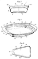
- Fig. 4 is an oblique perspective view from above of a first embodiment of a container according to the present invention and;
- Fig. 5 is a top plan view of an alternative embodiment of the container body.
- Referring to the drawings, there is shown a container 1 with a
container body bottom 19 and an opening portion ormouth 13. Alid 20 which is provided with acentral lid panel 24 surrounded by anedge region 25, is, in its edge region, connected, by means of one or more sealing andcontinuous joints 21, around the opening to the opening portion of the container body. As a rule, each joint consists of a glued or welded seam joint, Generally, the joints are of tear-off design, whereby the opening of the closed container 1 will be facilitated. In the drawings, the lid is illustrated in one preferred embodiment according to which it is designed as a foil or membrane. Thebottom 19 of the container body is provided with one or more standingsurfaces 12 located in aplane 11. In one preferred embodiment, one or more circumferentially extending standing surfaces are employed. In the illustrated embodiment, theopening 13 of the container body is provided with a continuous shoulder orledge 14 which, as a rule, is disposed but partly to surround the opening interiorly and is at least partly countersunk in relation to anopening edge surface 15 which constitutes an upper bounding surface for the opening 13 of thecontainer body 10. In other embodiments, the shoulder or ledge surrounds the entire opening and, in this instance, is countersunk in relation to a most proximally locatedopening edge surface 15. In the embodiments illustrated in the drawings, the opening edge portion merges into a portion of the opening in aflared flange 16 with an upper boundingsurface 17. The distance between theshoulder 14 and theopening edge surface 15 varies about the circumference of the opening portion and is at its greatest in the one end region of the container body, this region being, in the embodiment provided with theflared flange 16, located opposite the flange. - In the embodiments shown on the drawings, the lid is continuously and sealingly connected to the
flared flange 16 as well as to the sholder orledge 14 by means of the joint orjoints 21, respectively. As a rule, the shoulder and the flared flange, respectively, are provided with at least one continuous and generally circumferentially extendingridge 18 to which the lid is connected in a factory-sealed container. In Fig. 4, the ridge is shown with atip 50 which, according to the embodiment illustrated in Fig. 4, is disposed on theflared flange 16. The provision of the tip reduces the magnitude of the rupture forces required for initiating, on opening of the factory-sealed container, the separation of the lid from theridge 18. The ridge is disposed on the upper surface of theshoulder 14 and, in the embodiments shown on the drawings, continues along the upper bounding surface of theflared flange 16. Thejoint 21 is located in aplane 22 which makes an acute angle with theplane 11 through the standingsurface 12 of the container and also makes an acute angle with theopening edge surface 15. As a rule, this angle is of the order of magnitude of between 2 and 15°. The above-described construction refers to an embodiment which satisfies the disposition, as called for according to the present invention, of that defining bounding of the storage space constituted by the lid, namely a disposition in which bounding or definition portions of the lid are located more proximal the standing surface or surfaces of the container than other portions. - In Fig. 4, an alternative embodiment is shown by broken lines, according to which a folded
portion 23 of the lid forms a gripping device for opening the factory-sealed container. The folded lid portion is illustrated in one embodiment in which it is located in a region of the opening where the distance between theopening edge 15 and theshoulder 14 is at its greatest. As a rule, the shoulder is here provided with abroader portion 51 in order to make room for the spiculated design of theridge 18. In Fig. 4, it is assumed that the lid consists of a translucent material. - In certain embodiments, the
edge region 25 of thelid 20 is located on a level which differs from the level of thelid panel 24. In such instance, the orientation of the lid panel is such as to correspond substantially with the orientation of the edge region. - In the figures, filling goods supplied to the container is designated by
reference numeral 30. In the figures, the filling goods are marked as consisting of a liquid whose surface is designated 32. In certain physical applications, the liquid consists of a brine solution in which, for instance, herring or herring pieces are stored. Astratiform space 31 is formed between the lid and theliquid surface 32, the space being, in Fig. 1, of substantially uniform thickness, while being, in Fig. 2, of cuneiform cross section. The volumes of these spaces substantially agree in both Figures. - Fig. 1 shows a
retainer 40 provided for supporting the container body against the underside of theshoulder 14 and against the underside of the flaredflange 16. Theupper abutment surface 41 of theretainer 40 for cooperation with the underside of theshoulder 14 and the flaredflange 16 is located substantially in the horizontal plane. Theplane 22, whose orientation corresponds to the orientation of that plane in which the connection orjoint 21 is located, will consequently be of an orientation which lies substantially in the horizontal plane. In the embodiments shown in the drawings, the orientation of theplane 22 has its counterpart in the plane in which the upper bounding surface of theshoulder 14 and the upper boundingsurface 17 of theflared flange 16 are located. - Fig. 2 shows a section of the factory-sealed container placed on a substantially horizontal substrate and with the container resting on the substrate by means of the standing
surface 12. It will be apparent from this drawing figure that the extent of thespace 31 has been reduced, in that a portion of thelid 20 is located below thelevel 33 which the liquid surface would have assumed if the lid had not prevented the liquid from assuming that level. As a result of the reduced extent of thespace 31, and thereby of theliquid surface 32, the risk is reduced that, for example herring packed in brine would rise above the surface of the liquid. - Fig. 5 shows one embodiment in which the container body is of a design which entails that when the closed container is placed on a flat substrate, the size of the
liquid surface 32 is reduced in comparison with that which applies for substantially rectangular containers, at the same time as the thickness of (the height of) thestratiform space 31 is increased in the region most proximal theflared flange 16. - When a container is filled, this is placed in the
retainer 40 and a pre-determined amount of liquid, for instance brine, is filled into the container. Thereafter, the solid bodies such as herring pieces are, where applicable, added, the liquid level rising somewhat. Such packing of these solid bodies if often effected manually, with the result that the number of bodies thus packed and the total volume thereof may vary slightly from container to container and thereby also the liquid levels which are obtained in each container. Theshoulder 14 and the flaredflange 16 are located in the horizontal plane, for which reason overfilling of the container will be prevented because any possible excess liquid will run out over the flaredflange 16. In those physical applications where the liquid is supplied in a pre-determined amount once the bodies have been placed in the container, a corresponding overflow drainage of liquid will, naturally, take place. - When the filling operation is completed, the lid is sealingly connected, by means of one or
more joints 21 which are formed by, for instance, heat welding, ultrasonic welding, hot melt etc., to the upper side of theshoulder 14 and, where applicable, to theflange 16. Theridge 18 ensures that no liquid gathers in the region where the sealing connection between the container body and the lid is established. This procedure avoids the risk of untight closure of the container in applications in which, for instance, the choice of materials for the lid and container body - in combination with the connection technology employed - entails a risk of untight connection at points where liquid might gather. - During transport and in opening of the factory-sealed container, the container is of an orientation which corresponds to that illustrated in Fig. 2. This implies that the opening
edge surface 15 of the container body is located substantially in the horizontal plane and, thereby, at approximately equidistant spaced apart relationship from that level the liquid surface assumes in conjunction with the opening of the container. The distance between the upper bounding surface of the openingedge surface 15 and the liquid surface will, thereby, be sufficiently great to minimize the risk that liquid slops over the opening edge surface in conjunction with opening of the container or when the container is handled while being opened. - The above detailed description has referred to but a limited number of embodiments of the present invention, but the skilled reader of this specification will readily perceive that the present invention encompasses a large number of embodiments without departing from the scope of the appended claims.
Claims (10)
Applications Claiming Priority (2)
| Application Number | Priority Date | Filing Date | Title |
|---|---|---|---|
| SE8602744 | 1986-06-19 | ||
| SE8602744A SE8602744L (en) | 1986-06-19 | 1986-06-19 | PACKAGING |
Publications (2)
| Publication Number | Publication Date |
|---|---|
| EP0270657A1 EP0270657A1 (en) | 1988-06-15 |
| EP0270657B1 true EP0270657B1 (en) | 1992-01-29 |
Family
ID=20364862
Family Applications (1)
| Application Number | Title | Priority Date | Filing Date |
|---|---|---|---|
| EP87904355A Expired EP0270657B1 (en) | 1986-06-19 | 1987-06-17 | A container for liquids, a method for filling and sealing the same |
Country Status (11)
| Country | Link |
|---|---|
| US (1) | US4836401A (en) |
| EP (1) | EP0270657B1 (en) |
| JP (1) | JPS63503533A (en) |
| AT (1) | ATE72190T1 (en) |
| AU (1) | AU595345B2 (en) |
| DE (1) | DE3776516D1 (en) |
| DK (1) | DK83288A (en) |
| IS (1) | IS1459B6 (en) |
| NO (1) | NO165873C (en) |
| SE (1) | SE8602744L (en) |
| WO (1) | WO1987007879A1 (en) |
Families Citing this family (11)
| Publication number | Priority date | Publication date | Assignee | Title |
|---|---|---|---|---|
| US5058761A (en) * | 1990-09-10 | 1991-10-22 | Bryan Foods, Inc. | Reclosable package and a base portion of the package |
| USD453094S1 (en) | 1997-08-29 | 2002-01-29 | Printpack Illinois, Inc. | Hot-fill container |
| USD409448S (en) * | 1997-09-10 | 1999-05-11 | Gerber Products Company | Infant feeding dish |
| USD465154S1 (en) | 2001-12-18 | 2002-11-05 | Printpack Illinois, Inc. | Container |
| ITMC20070004U1 (en) * | 2007-01-19 | 2008-07-20 | Clabo Group Spa | REFRIGERATED COUNTER WITH ICE CREAM TRAYS IN TRANSPARENT MATERIAL. |
| EP2138408A1 (en) * | 2008-06-10 | 2009-12-30 | Nestec S.A. | Group of jars for food products |
| US8844310B2 (en) * | 2009-12-14 | 2014-09-30 | Whirlpool Corporation | High capacity ice storage in a freezer compartment |
| US9861778B2 (en) | 2013-03-15 | 2018-01-09 | Resmed Limited | Humidifier reservoir |
| EP4122517B1 (en) | 2013-03-15 | 2025-08-06 | ResMed Pty Ltd | Respiratory pressure device |
| USD782749S1 (en) * | 2016-02-22 | 2017-03-28 | Yuko Michizoe | Pet feeding dish |
| EP4410346B1 (en) | 2018-12-18 | 2026-02-18 | ResMed Pty Ltd | Humidifier reservoir |
Family Cites Families (9)
| Publication number | Priority date | Publication date | Assignee | Title |
|---|---|---|---|---|
| US938555A (en) * | 1909-03-02 | 1909-11-02 | A L Haasis | Cover for tanks used in skimming sullage from crucibles into water. |
| US3128002A (en) * | 1962-02-12 | 1964-04-07 | Arvin Ind Inc | Carrying case |
| US3129840A (en) * | 1963-03-04 | 1964-04-21 | Halpern Joel | Container for liquids |
| US3642162A (en) * | 1969-06-27 | 1972-02-15 | Flambeau Plastics Corp | Ice cube bin |
| US3952910A (en) * | 1975-09-04 | 1976-04-27 | Wheeler Richard A | Self-sealing container closure |
| US4113095A (en) * | 1976-11-26 | 1978-09-12 | Van Dorn Company | Tray-type processed food containers |
| DE2829153A1 (en) * | 1978-07-03 | 1980-01-17 | Kurt Lohwasser | Curved food package and cover - has cover edge drawn up over part of circumference towards vertical cover wall |
| US4541542A (en) * | 1984-03-12 | 1985-09-17 | Gregory Florentino | Paint tray cover |
| US4754874A (en) * | 1987-01-28 | 1988-07-05 | Haney Robert J | Bar soap and its package |
-
1986
- 1986-06-19 SE SE8602744A patent/SE8602744L/en not_active Application Discontinuation
-
1987
- 1987-06-16 IS IS3232A patent/IS1459B6/en unknown
- 1987-06-17 AT AT87904355T patent/ATE72190T1/en active
- 1987-06-17 US US07/156,925 patent/US4836401A/en not_active Expired - Fee Related
- 1987-06-17 WO PCT/SE1987/000284 patent/WO1987007879A1/en not_active Ceased
- 1987-06-17 DE DE8787904355T patent/DE3776516D1/en not_active Expired - Fee Related
- 1987-06-17 AU AU75857/87A patent/AU595345B2/en not_active Ceased
- 1987-06-17 JP JP62503947A patent/JPS63503533A/en active Pending
- 1987-06-17 EP EP87904355A patent/EP0270657B1/en not_active Expired
-
1988
- 1988-02-10 NO NO880579A patent/NO165873C/en unknown
- 1988-02-18 DK DK083288A patent/DK83288A/en not_active Application Discontinuation
Also Published As
| Publication number | Publication date |
|---|---|
| DK83288D0 (en) | 1988-02-18 |
| DE3776516D1 (en) | 1992-03-12 |
| JPS63503533A (en) | 1988-12-22 |
| NO165873C (en) | 1991-04-24 |
| IS3232A7 (en) | 1987-12-20 |
| NO165873B (en) | 1991-01-14 |
| AU7585787A (en) | 1988-01-12 |
| WO1987007879A1 (en) | 1987-12-30 |
| US4836401A (en) | 1989-06-06 |
| SE8602744L (en) | 1987-12-20 |
| AU595345B2 (en) | 1990-03-29 |
| ATE72190T1 (en) | 1992-02-15 |
| EP0270657A1 (en) | 1988-06-15 |
| NO880579D0 (en) | 1988-02-10 |
| SE8602744D0 (en) | 1986-06-19 |
| IS1459B6 (en) | 1991-01-16 |
| DK83288A (en) | 1988-02-18 |
| NO880579L (en) | 1988-02-10 |
Similar Documents
| Publication | Publication Date | Title |
|---|---|---|
| US3637132A (en) | Pressure release package or container | |
| US5655706A (en) | Reusable top for use with a disposable storage container | |
| EP0442433B1 (en) | Reclosable container | |
| US4836401A (en) | Container for liquids and method for filling and sealing the container | |
| EP0675053B1 (en) | Process for making container of plastified sheet material and container obtained with this process | |
| LT3815B (en) | Packaging container and blank thereto | |
| US4498585A (en) | Denesting paperboard container | |
| UA74860C2 (en) | Container | |
| GB2136783A (en) | Container | |
| WO2001081208A3 (en) | Collapsible storage tank for liquids | |
| KR970003303B1 (en) | A reclosable container of synthetic material | |
| KR830007375A (en) | Containers for food freezing and storage | |
| US5954263A (en) | Liquid-tight boat-shaped packaging tray and its manufacturing method | |
| AU2010266321A1 (en) | Bag in box packaging having a tap articulating assembly | |
| US5480057A (en) | Bulk container having flexible inner container and rigid outer container | |
| CA3107405A1 (en) | Paper container | |
| CA1280982C (en) | Packages | |
| EP0203955B1 (en) | Fluid-tight sealed container with lid | |
| JPH0248377Y2 (en) | ||
| JPH0577828A (en) | Stackable plastic container with stopper | |
| GB2152469A (en) | Stackable container with dilutable product | |
| JP3380847B2 (en) | Fluid content take-out device | |
| US3043489A (en) | Package for liquids and other materials | |
| GB2107291A (en) | Closure assembly for a tubular container | |
| RU239243U1 (en) | Container for packaging the finished product |
Legal Events
| Date | Code | Title | Description |
|---|---|---|---|
| PUAI | Public reference made under article 153(3) epc to a published international application that has entered the european phase |
Free format text: ORIGINAL CODE: 0009012 |
|
| AK | Designated contracting states |
Kind code of ref document: A1 Designated state(s): AT BE CH DE FR GB IT LI LU NL SE |
|
| 17P | Request for examination filed |
Effective date: 19880614 |
|
| 17Q | First examination report despatched |
Effective date: 19900709 |
|
| GRAA | (expected) grant |
Free format text: ORIGINAL CODE: 0009210 |
|
| AK | Designated contracting states |
Kind code of ref document: B1 Designated state(s): AT BE CH DE FR GB IT LI LU NL SE |
|
| PG25 | Lapsed in a contracting state [announced via postgrant information from national office to epo] |
Ref country code: LI Effective date: 19920129 Ref country code: CH Effective date: 19920129 |
|
| REF | Corresponds to: |
Ref document number: 72190 Country of ref document: AT Date of ref document: 19920215 Kind code of ref document: T |
|
| REF | Corresponds to: |
Ref document number: 3776516 Country of ref document: DE Date of ref document: 19920312 |
|
| ITF | It: translation for a ep patent filed | ||
| PGFP | Annual fee paid to national office [announced via postgrant information from national office to epo] |
Ref country code: FR Payment date: 19920430 Year of fee payment: 6 |
|
| REG | Reference to a national code |
Ref country code: CH Ref legal event code: PL |
|
| PGFP | Annual fee paid to national office [announced via postgrant information from national office to epo] |
Ref country code: GB Payment date: 19920603 Year of fee payment: 6 |
|
| PGFP | Annual fee paid to national office [announced via postgrant information from national office to epo] |
Ref country code: SE Payment date: 19920604 Year of fee payment: 6 Ref country code: BE Payment date: 19920604 Year of fee payment: 6 |
|
| ET | Fr: translation filed | ||
| PG25 | Lapsed in a contracting state [announced via postgrant information from national office to epo] |
Ref country code: LU Free format text: LAPSE BECAUSE OF NON-PAYMENT OF DUE FEES Effective date: 19920630 |
|
| PGFP | Annual fee paid to national office [announced via postgrant information from national office to epo] |
Ref country code: NL Payment date: 19920630 Year of fee payment: 6 Ref country code: AT Payment date: 19920630 Year of fee payment: 6 |
|
| PGFP | Annual fee paid to national office [announced via postgrant information from national office to epo] |
Ref country code: DE Payment date: 19920825 Year of fee payment: 6 |
|
| PLBE | No opposition filed within time limit |
Free format text: ORIGINAL CODE: 0009261 |
|
| STAA | Information on the status of an ep patent application or granted ep patent |
Free format text: STATUS: NO OPPOSITION FILED WITHIN TIME LIMIT |
|
| 26N | No opposition filed | ||
| PG25 | Lapsed in a contracting state [announced via postgrant information from national office to epo] |
Ref country code: GB Effective date: 19930617 Ref country code: AT Effective date: 19930617 |
|
| PG25 | Lapsed in a contracting state [announced via postgrant information from national office to epo] |
Ref country code: SE Effective date: 19930618 |
|
| PG25 | Lapsed in a contracting state [announced via postgrant information from national office to epo] |
Ref country code: BE Effective date: 19930630 |
|
| BERE | Be: lapsed |
Owner name: PLM A.B. Effective date: 19930630 |
|
| PG25 | Lapsed in a contracting state [announced via postgrant information from national office to epo] |
Ref country code: NL Effective date: 19940101 |
|
| GBPC | Gb: european patent ceased through non-payment of renewal fee |
Effective date: 19930617 |
|
| NLV4 | Nl: lapsed or anulled due to non-payment of the annual fee | ||
| PG25 | Lapsed in a contracting state [announced via postgrant information from national office to epo] |
Ref country code: FR Effective date: 19940228 |
|
| PG25 | Lapsed in a contracting state [announced via postgrant information from national office to epo] |
Ref country code: DE Effective date: 19940301 |
|
| REG | Reference to a national code |
Ref country code: FR Ref legal event code: ST |
|
| EUG | Se: european patent has lapsed |
Ref document number: 87904355.2 Effective date: 19940110 |
|
| PG25 | Lapsed in a contracting state [announced via postgrant information from national office to epo] |
Ref country code: IT Free format text: LAPSE BECAUSE OF NON-PAYMENT OF DUE FEES Effective date: 20050617 |