EP0270053B1 - Apparatus and method for plugging a tube - Google Patents
Apparatus and method for plugging a tube Download PDFInfo
- Publication number
- EP0270053B1 EP0270053B1 EP87117681A EP87117681A EP0270053B1 EP 0270053 B1 EP0270053 B1 EP 0270053B1 EP 87117681 A EP87117681 A EP 87117681A EP 87117681 A EP87117681 A EP 87117681A EP 0270053 B1 EP0270053 B1 EP 0270053B1
- Authority
- EP
- European Patent Office
- Prior art keywords
- plug
- shell
- pull
- cavity
- rod member
- Prior art date
- Legal status (The legal status is an assumption and is not a legal conclusion. Google has not performed a legal analysis and makes no representation as to the accuracy of the status listed.)
- Expired - Lifetime
Links
Images

Classifications
-
- F—MECHANICAL ENGINEERING; LIGHTING; HEATING; WEAPONS; BLASTING
- F16—ENGINEERING ELEMENTS AND UNITS; GENERAL MEASURES FOR PRODUCING AND MAINTAINING EFFECTIVE FUNCTIONING OF MACHINES OR INSTALLATIONS; THERMAL INSULATION IN GENERAL
- F16L—PIPES; JOINTS OR FITTINGS FOR PIPES; SUPPORTS FOR PIPES, CABLES OR PROTECTIVE TUBING; MEANS FOR THERMAL INSULATION IN GENERAL
- F16L55/00—Devices or appurtenances for use in, or in connection with, pipes or pipe systems
- F16L55/10—Means for stopping flow in pipes or hoses
- F16L55/12—Means for stopping flow in pipes or hoses by introducing into the pipe a member expandable in situ
- F16L55/128—Means for stopping flow in pipes or hoses by introducing into the pipe a member expandable in situ introduced axially into the pipe or hose
- F16L55/13—Means for stopping flow in pipes or hoses by introducing into the pipe a member expandable in situ introduced axially into the pipe or hose the closure device being a plug fixed by plastic deformation
-
- B—PERFORMING OPERATIONS; TRANSPORTING
- B25—HAND TOOLS; PORTABLE POWER-DRIVEN TOOLS; MANIPULATORS
- B25B—TOOLS OR BENCH DEVICES NOT OTHERWISE PROVIDED FOR, FOR FASTENING, CONNECTING, DISENGAGING, OR HOLDING
- B25B27/00—Hand tools, specially adapted for fitting together or separating parts or objects whether or not involving some deformation, not otherwise provided for
- B25B27/02—Hand tools, specially adapted for fitting together or separating parts or objects whether or not involving some deformation, not otherwise provided for for connecting objects by press fit or detaching same
- B25B27/026—Hand tools, specially adapted for fitting together or separating parts or objects whether or not involving some deformation, not otherwise provided for for connecting objects by press fit or detaching same fluid driven
-
- F—MECHANICAL ENGINEERING; LIGHTING; HEATING; WEAPONS; BLASTING
- F28—HEAT EXCHANGE IN GENERAL
- F28F—DETAILS OF HEAT-EXCHANGE AND HEAT-TRANSFER APPARATUS, OF GENERAL APPLICATION
- F28F11/00—Arrangements for sealing leaky tubes and conduits
- F28F11/02—Arrangements for sealing leaky tubes and conduits using obturating elements, e.g. washers, inserted and operated independently of each other
Definitions
- This invention generally relates to plugging tubes by means of a radially expandable plug, and specifically concerns both an apparatus and a method for hydraulically plugging relatively small diameter heat exchange tubes that are surrounded by a structure that is not inelastically deformable, such as a tubesheet.
- Plugging devices for plugging the heat exchanger tubes in nuclear steam generators are known in the prior art. Generally, such devices are used to seal off one or more of the U-shaped heat exchanger tubes contained within the nuclear steam generator when the walls of these tubes become corroded beyond repair. If such tubes are not plugged or repaired, they may crack and allow radioactive water from the primary side of the generator to leak into the non-radioactive water in the secondary side. This, in turn, could result in the radioactive contamination of the non-radioactive steam that Westinghouse-type nuclear generators provide to turn the turbines of the electric generators of the plant. Hence the plugging of potentially defective heat exchanger tubes is an important maintenance operation that must be reliably carried out.
- Such prior art plugs generally comprise a tubular shell that is open on one end and closed at the other end, and which contains a frustoconically shaped expander member.
- the expander element is a round wedge shaped like a common cork used to seal a bottle, and is disposed completely within the interior of the shell with its larger circular end in abutment with the inner surface of the closed distal end of the plug shell.
- the interior walls of the shell are slightly tapered by increasing the thickness of the shell walls from the distal closed end to the proximal open end.
- the cork-shaped wedge When the cork-shaped wedge is forcefully pulled from the closed end toward the open end of the shell by a hydraulic ram, itwill radially expandthe plug into sealing engagement with the inner wall of a tube by a wedging action.
- a plug design is described in EP-A-0 044 982 or EP-A-0 058 850.
- the cork-shaped expan- derwedge is forcefully pulled from the distal to the proximal end of the plug shell by means of a pull-rod that is connected to the expander element on one end and to a hydraulic ram on the other end along the longitudinal axis of the expander member.
- this particular plug design is capable of reliably and conveniently plugging the open ends of a corroded U-shaped tube in regions where the tube is surrounded by a structure that is not inelastically deformable, such as the thick steel tubesheet that divides the primary from the secondary side of the steam generator.
- the forceful pulling of the cork-shaped expander member along the axis of the shell not only radially expands the wall of the shell outwardly as the member is wedgingly drawn toward the proximal end of the shell, but further applies an extruding force to the metallic walls of the shell along the longitudinal axis of the tube.
- an explosive charge is used in lieu of a hydraulically operated pull-rod to move the cork-shaped wedge along the longitudinal axis of the tube shell.
- the expansion member is situated near the open end of the tubeshell, and the explosive charge is disposed between the proximal end of the shell and the top surface of the expansion member.
- the cork-shaped wedge is pushed along the longitudinal axis of the shell until it abuts the closed distal end of the plug.
- Still another limitation associated with both of these prior art plugs is the relatively narrow range of inner diameter tube dimensions that a plug having a particular outer diameter can accommodate. Specifically, such prior art plugs can only accommodate tubes having an inner diameter that is less than 1.524 millimeters (60 mils) greater than the outer diameter of the plug. Since the inner diameter of the heat exchanger tubes often varies some between tubes in the same nuclear steam generator and can vary considerably between different steam generators, the manufacture of many different sizes of such plugs is necessary. This limitation requires the maintenance operators that perform the plugging operation to carry a large inventory of different plug sizes in order to service any given utility.
- a final limitation inherent in both design variations stems from the fact that the cork-shaped expander wedge remains within the tapered interior of the plug shell after the plugging operation. The permanent presence of this wedge in the plug interior makes it difficult to inspect the interior of the plug for leakage. This is a significant drawback, since federal regulations require utilities operating nuclear steam generators to make frequent and thorough inspections of these devices in order to minimize the chances of malfunction.
- plugging apparatus that is capable of reliably plugging small diameter as well as large diameter heat exchanger tubes in nuclear steam generators.
- a device should be easily installable even in heat exchanger tubes of limited access, such as the tubes situated around the periphery of the tubesheet.
- this device were capable of successfully and reliably plugging heat exchanger tubes of widely varying inner diameters with plugs of a single size in order to minimize the number of sizes of such plugs that must be carried to a particular utility.
- the interiors of the plugs installed should be readily inspectable at any time after installation.
- the invention resides in a plug installation apparatus as defined in claims 1 to 3, and in a method of plugging a conduit as defined in claims 4 to 6.
- the invention provides for hydraulically applying a radially expansive force within the cavity of the plug while applying a compressive force across the portion of the plug containing the cavity that is substantially orthogonal to the radially expansive force in order to inelastically expand the plug into the walls of the conduit.
- the plug contains a fluid-receiving cavity that is radially deformable into sealing engagement with the inner wall of a conduit such as an InconeI•tube when a radially expansive force and a compressive force are simultaneously applied thereto.
- the preferred embodiment described herein provides an apparatus that includes an expansion assembly that includes a combined hydraulic expander and pull-rod mechanism for simultaneously applying a radially expansive hydraulic force within the cavity of the plug and a compressive force across the plug in a direction that is substantially in alignment with the longitudinal axis of the tube.
- the combination of the radially expansive force and the compressive force inelastically deforms the plug into sealing engagement within the tube even in cases where the tube is surrounded by a structure that is difficult to inelastically deform, such as the thick steel tubesheet of a nuclear steam generator.
- the compressive force applied onto the plug by the expansion mechanism may also be used to sealingly engage the open end of the plug against a sealing member in order to prevent the escape of pressurized hydraulic fluid from the cavity within the plug.
- This same compressive force may further be used to counteract a net force on the plug along the longitudinal axis of the tube that is created by the injection of pressurized hydraulic fluid into the plug cavity, and to thereby stationarily position the plug within the tube during the expansion operation.
- the pull-rod mechanism of the expansion assembly includes a pull-rod member, and the plug includes a means for detachably connecting the distal end of the pull-rod member to a point along the distal end of its internal cavity.
- This connecting means is preferably formed from mating threads on the distal end of the pull-rod member and the distal end of the plug cavity.
- the pull-rod member may be dimensioned so that an annular space is defined between the outer surface of the rod and the internal surface of the plug, and the expansion mechanism may also include a bore for conducting this fluid in this annular space.
- the pull-rod member may include a piston means that communicates with the pressurized hydraulic fluid for generating a tensile force on the distal end of the pull-rod member from the pressure of the fluid admitted into the plug during the expansion operation.
- the diameter of the proximal end of the pull-rod is larger than the diameter of the distal end of the rod, and the working face of the piston means is formed at the junction between the two ends.
- the plug may be formed from a shell having a closed distal end and an open proximal end that leads into the aforementioned fluid-receiving cavity.
- the plug may further have a substantially cylindrical middle portion that circumscribes the fluid-receiving cavity.
- This middle portion preferably has relatively thin walls while the walls of the shell in the distal and proximal portions that flank the middle portion are preferably thicker in order to facilitate the deformation of the middle portion of the shell into a radially expanded shape.
- these thicker flanking shell walls may each include a tapered section whose thinnest portions melds with the distal and proximal edges of the middle portion of the shell.
- tapered wall sections may be formed by providing enlarged, frustoconical tapers on the outside distal and proximal sections of the plug shell, or by forming the cavity in the interior of the shell with what is known as a "bottle bore" in the art.
- the middle portion is preferably circumscribed by six uniformly spaced lands, each of which is slightly tapered along its exterior edge in order to effect a localized region of sealing between the exterior of the plug, and the interior wall of the tube.
- the apparatus and method of the invention provide a convenient and reliable way to plug both small diameter and peripherally located tubes within the tubesheet of a nuclear steam generator. Because no expander element is left in the interior of the plug after the plugging operation is performed, the resulting plug is easily inspectable.
- the tube plugging apparatus 1 of the invention is particularly adapted for plugging Inconel @ tubes 3 mounted in the tubesheets 4 of nuclear steam generators.
- the plugging apparatus 1 comprises a plug 5 having a concentrically disposed cavity 6, and an expansion assembly 7 that is connected to a source of pressurized fluid and which has a hydraulically operated pull-rod mechanism 8 for applying both a radially expansive force and a compressive force on the plug 5.
- the plug 5 of the invention is formed from a generally tubular shell 11 having a distal closed end 12 that terminates in a wall 13 whose outer surface is circumscribed by a chamber 14, and a proximal open end 15 having a circular opening 16 circumscribed by a flat annular wall 17.
- the proximal end of the cavity 6 terminates in the circular opening 16, while the distal end 21 of this cavity 6 terminates at the inner surface of the wall 13.
- the distal cavity ends 21 of both of the plug embodiments are surrounded by a plurality of threads 23 for engagement with a pull-rod member that will be described hereinafter.
- Both of the plug embodiments illustrated in Figures 2 and 3 further include a tubular middle portion 25 where the shell wall 27 is relatively thin with respect to the flanking walls.
- the exterior of the middle portion wall 27 is circumscribed by six, equidistantly spaced lands 29, each of which includes a tapered outer edge 31.
- the middle portion wall 27 is flanked by thicker distal and proximal wall sections 33 and 35, respectively.
- Each of the distal and the proximal thicker wall sections 33 and 35 includes a tapered section 37 and 39.
- the angle of the taper of the sections 37 and 39 is approximately 10° with respect to the longitudinal axis of the plug 5.
- Each of the tapered sections 37 and 39 includes an inner edge 41, 43 that melds in with the relatively thinner wall 27 of the middle portion 25, as well as an outer edge 45, 47 that melds in with the relatively thicker wall sections 33, 35 located on the distal and proximal ends of the plug 5, respectively.
- the cavity 6 of the Figure 3 embodiment is formed by a "bottle bore" rather than from a cylindrically shaped bore.
- the bottle bore has the effect of tapering the wall portions 37 and 39 from the inside of the plug 5, rather than from the outside, as is the case in the Figure 2 embodiment.
- the Figure 3 embodiment is somewhat shorter along its longitudinal axis than the Figure 2 embodiment.
- the lands 29 must be manufactured with a fairly large radial extent relative to the outer surface of the middle portion 25 of the plug 6 if they are to engage the inner wall of the tube 3 at the end of the expansion operation.
- the Figure 3 embodiment solves the need for manufacturing such radially long lands by providing the required tapered sections 37 and 39 with a bottle bore. But since the provision of such a bottle bore significantly increases the manufacturing cost of the Figure 3 embodiment of the plug 5, neither embodiment is strongly preferred over the other.
- the pull-rod mechanism 8 of the expansion assembly 7 includes a pull-rod member 52 having a distal shaft 54 that is integrally and concentrically connected with a relatively thicker proximal shaft 55 at joint 59.
- An annular piston face 60 is defined around the upper end of the joint 59. This piston face 60 generates and applies a tensile force on the distal shaft 54whenever pressurized hydraulic fluid is applied thereto. Since the expansion assembly 7 is designed so that the piston face 60 communicates with the pressurized fluid injected into the cavity 6 of the plug 5, the provision of the piston face 60 is a highly advantageous feature, since it obviates the need for a separate hydraulic ram to apply a tensile force on the pull-rod member 52.
- the narrow distal shaft 54 of the pull-rod member terminates in a plurality of threads 56 which are matable with the threads 23 present around the distal end of the cavity 6 in each embodiment of the plug 5.
- the distal shaft 54 of the pull-rod member 52 has a smaller outer diameter than the inner diameter of the cavity 6 in each embodiment of the plug 5, so that an annular space 57 is defined between the outer surface of the distal shaft 54 and the inner surface of the cavity 6 whenever the pull-rod member 52 and a plug are threadedly mated in the manner illustrated in Figure 1A.
- This annular space 57 conducts pressurized hydraulic fluid into the cavity 6 in order that the tubular middle portion 25 of the plug 5 may be expanded into seating engagement with the inner walls of a tube 3.
- the bottom end of the proximal shaft 55 terminates in a square end 61 that is receivable within the socket of a wrench (not shown) when it becomes necessary to unscrew the threaded end 56 of the pull-rod member 52 from the threads 23 of the plug 5.
- the pull-rod member 52 of the pull-rod mechanism 8 is slidably housed within an inlet block 62.
- This inlet block 62 includes a vertically disposed, telescoping bore 64 having a proximal bore section 66 that slidably receives the relatively narrower distal shaft 54 of the pull-rod member 52.
- An annular shoulder 70 is defined at the top of the bore section 66 that limits the extent to which the piston face 60 of the pull-rod member 52 can slide in the vertical direction within the block 62.
- the bottom of the bore section 66 terminates in an enlarged threaded section 67.
- the outer diameter of the distal bore section 68 is deliberately made larger than the outer diameter of the distal shaft 54.
- only a minimum amount of clearance is provided between the outer diameter of the proximal shaft 55 and the inner surface of the proximal bore section 66 in order to discourage the flow of hydraulic fluid out of the bottom of the inlet block 62.
- a urethane sealing ring 72 is provided at the lower end of the inlet block 62.
- This ring 72 forms a seal between the proximal shaft 55 and the proximal bore section 66 without interfering with the sliding movement of the pull-rod member 52 through the block 62.
- the urethane ring 72 is compressed into sealing engagement around the proximal shaft 55 by a steel compression ring 74.
- the ring 74 is in turn held in place by a threaded collar 76 that is screwed into the enlarged, threaded portion 67 of the bore section 66.
- the threaded collar includes wrench flats 78 along its bottom sides to facilitate the assembly and disassembly of the expansion assembly 7.
- a laterally disposed inlet bore 80 is also provided in the inlet block 62.
- the left end of this bore 80 conducts pressurized hydraulic fluid upwardly to the annular space 57 between the distal shaft 54 of the pull-rod member 52 and the cavity 6 of the plug 5, and downwardly over the annular shoulder 70 and against the piston face 60.
- the right end of the bore 80 terminates in an enlarged, threaded end 82 for receiving a fluid-tight fitting (not shown) that connects the block 62 to a source of pressurized hydraulic fluid 83.
- the source of hydraulic fluid is Hydroswage @ brand hydraulic expander manufactured by Haskel, Inc. of Burbank, California, USA.
- the terminal end of the distal bore section 68 is surrounded by an integrally formed sealing ring 84.
- the outer diameter of the sealing ring 84 is smaller than the inner diameter of the tube 3, and the height of the ring 84 is at least 3.175 millimeters (one-eighth of an inch).
- the annular upper surface 86 of the sealing ring 84 engages the flat annular wall 17 of the plug.
- an O-ring 88 is seated in an annular groove 90 that circumscribes the annular upper surface 86 of the ring 84.
- the annular groove 90 not only seats the 0-ring 88, but prevents it from blowing out during the expansion operation.
- a plug 5 is mounted onto the pull-rod member 52 of the expansion assembly 7 by manually inserting the distal shaft end 54 of the rod 52 into the proximal open end 15, and screwing the threads 23 and 56 finger-tight together.
- the flat annular wall 17 at the bottom of the plug 5 sealingly engages the top of the O-ring 88 located on the top surface 86 of the ring 84.
- a pre-load tensile sealing force of between 1 kilonewtons (300 pounds-force) and 2 kilonewtons (500 pounds-force) is applied to the pull-rod member 52 by introducing relatively low pressure hydraulic fluid into the lateral bore 80.
- This pressurized fluid flows downwardly against the piston face 60, where it applies a hydraulically pushing force to the pull-rod member 52.
- This hydraulic force in turn causes the distal shaft 54 of the member 52 to apply a compressive force to the plug 5 that securely seats its flat annular bottom 17 tightly against the O-ring 88.
- some of the hydraulic fluid also flows in the annular space 57 between the proximal shaft 54 and the plug cavity 6. However, the pressure at this time is not great enough to create any significant radial expansion in the plug 5.
- the operator of the apparatus next inserts the plug 5 into the open end of a tube 3, and intensifies the pressure of the fluid until the shell 11 of the plug 5 is radially expanded.
- a plug 5 formed from Inconel• and having a diameter of about 11.176 millimeters (0.440 inches) such pressure amounts to about 193 megapascals (28,000 pounds per square inch).
- the application of such pressure to the inlet block 62 creates both a radially expansive force within the plug cavity 6 that is large enough to cause it to expand, as well as a tensile force of about 76 kilonewtons (1,700 pounds-force) on the pull-rod member 52.
- the combination of the radially expansive force provided by the hydraulic fluid and the compressive force applied by the pull-rod member 52 has four desirable effects on the plug 5.
- the radially expansive force expands the relatively thin-walled tubular portion 25 of the plug outwardly until the lands 29 forcefully and sealingly engage the inner wall of the tube 5, while the compressive force applied by the' pull-rod member 52 inelastically deforms the middle portion 25 of the plug 5 into this sealing position.
- the compressive force permanently deforms the middle portion 25 into this radially expanded position by providing a controlled buckling of the walls at the juncture between the tapered portions 37 and 39 of the walls of the plug 5, and the distal and proximal edges of the relatively thin-walled middle portion 25 of the plug 5.
- the second advantageous effect from the joint application of a compressive and radially expansive force on the plug 5 is the fact that the compressive force sealingly engages the annular face 17 of the plug 5 even more tightly against the O-ring 88 located on the upper surface 86 of the seating ring 84, thereby obviating the need for any sort of complex mechanism to contain the 193 megapascals (28,000 pounds per square inch) pressure within the cavity 6 of the plug 5 during the plugging operation.
- the third advantageous effect is that the compressive force applied by the pull-rod member 52 more than counteracts the net upwardly directed force that the hydraulic fluid applies onto the plug 5, thereby holding it in a completely stationary position throughout the entire plugging operation.
- the fourth and final positive effect is best understood with respect to Figure 4.
- the radially expansive force within the cavity 6 of the plug 5 is sufficient to force the tapered edges 31 of the lands 29 into the inner walls of the tube 3 during the plugging operation.
- the Inconel @ that forms the plug 5 will tend to "spring back" slightly along its longitudinal axis. This longitudinal spring back will cause the tapered ends 31 of the lands 29 to very tightly engage one of the sides of the slight notch that the lands 29 form by their forceful engagement of the wall of the tube 3 (see circled portions).
- the pull-rod member 52 is detached from the distal end of the cavity 6 of the plug 5 by grasping the square end 62 of the member 52 with a wrench, and unscrewing the threaded end 56 of the member 52 from the threads 23 within the plug 5.
- the inlet block 62 of the expansion assembly 7 should be placed against either the bottom edge of the tube 3 or the tubesheet 4 when the fluid pressure is intensified to 193 megapascals (28,000 pounds per square inch). If the top of the block 62 were so positioned, the longitudinal spring-back of the plug 5 could cause galling to occur between the lands 29 and the inner walls of the tube 3, thereby jeopardizing the integrity of the seal.
- the plug of the invention may be used to plug most any tube in any environment, and is particularly well suited to plug the heat exchange tubes in the tubesheets of fossil fuel power plants.
Landscapes
- Engineering & Computer Science (AREA)
- Mechanical Engineering (AREA)
- General Engineering & Computer Science (AREA)
- Physics & Mathematics (AREA)
- Thermal Sciences (AREA)
- Pressure Vessels And Lids Thereof (AREA)
- Pipe Accessories (AREA)
Description
- This invention generally relates to plugging tubes by means of a radially expandable plug, and specifically concerns both an apparatus and a method for hydraulically plugging relatively small diameter heat exchange tubes that are surrounded by a structure that is not inelastically deformable, such as a tubesheet.
- Plugging devices for plugging the heat exchanger tubes in nuclear steam generators are known in the prior art. Generally, such devices are used to seal off one or more of the U-shaped heat exchanger tubes contained within the nuclear steam generator when the walls of these tubes become corroded beyond repair. If such tubes are not plugged or repaired, they may crack and allow radioactive water from the primary side of the generator to leak into the non-radioactive water in the secondary side. This, in turn, could result in the radioactive contamination of the non-radioactive steam that Westinghouse-type nuclear generators provide to turn the turbines of the electric generators of the plant. Hence the plugging of potentially defective heat exchanger tubes is an important maintenance operation that must be reliably carried out.
- Such prior art plugs generally comprise a tubular shell that is open on one end and closed at the other end, and which contains a frustoconically shaped expander member. In one type of prior art plug, the expander element is a round wedge shaped like a common cork used to seal a bottle, and is disposed completely within the interior of the shell with its larger circular end in abutment with the inner surface of the closed distal end of the plug shell. Instead of being cylindrical, the interior walls of the shell are slightly tapered by increasing the thickness of the shell walls from the distal closed end to the proximal open end. When the cork-shaped wedge is forcefully pulled from the closed end toward the open end of the shell by a hydraulic ram, itwill radially expandthe plug into sealing engagement with the inner wall of a tube by a wedging action. Such a plug design is described in EP-A-0 044 982 or EP-A-0 058 850. In this particular plug design, the cork-shaped expan- derwedge is forcefully pulled from the distal to the proximal end of the plug shell by means of a pull-rod that is connected to the expander element on one end and to a hydraulic ram on the other end along the longitudinal axis of the expander member.
- In most instances, this particular plug design is capable of reliably and conveniently plugging the open ends of a corroded U-shaped tube in regions where the tube is surrounded by a structure that is not inelastically deformable, such as the thick steel tubesheet that divides the primary from the secondary side of the steam generator. The forceful pulling of the cork-shaped expander member along the axis of the shell not only radially expands the wall of the shell outwardly as the member is wedgingly drawn toward the proximal end of the shell, but further applies an extruding force to the metallic walls of the shell along the longitudinal axis of the tube. In a variation of this design, an explosive charge is used in lieu of a hydraulically operated pull-rod to move the cork-shaped wedge along the longitudinal axis of the tube shell. In such plugs, the expansion member is situated near the open end of the tubeshell, and the explosive charge is disposed between the proximal end of the shell and the top surface of the expansion member. When the charge is detonated, the cork-shaped wedge is pushed along the longitudinal axis of the shell until it abuts the closed distal end of the plug.
- Unfortunately, there are certain mechanicallimi- tations associated with these prior art plug designs that interfere with their usefulness in certain applications. For example, in plugs wherein a pull-rod is used to draw the cork-shaped wedge against the internally tapered walls, there is a limit as to the inner diameter of the tubes that such plugs can reliably seal. In nuclear steam generators utilizing heat exchanger tubes having inner diameters of approximately 12.7 mm (.50 inches) or greater, this mechanical limitation poses no problem. On the other hand, for tubes whose inner diameter is less than 12.7 mm (.50 inches), it becomes increasingly difficult to design a pull-rod capable of withstanding the tensile force necessary to draw the cork-shaped wedge throughout the entire longitudinal axis of the tubeshell. Even when the pull-rod is formed from the strongest commercially available materials, such as Vascomax®, it will have a tendency to break off in small diameter plugs since its own external diameter can be no larger than the minimum internal diameter of the tapered interior of the plug shell, and since the tensile strength of any material decreases expo- nentiallywith its diameter. One way of solving this problem is to reduce the angle of both the cork-shaped wedge and the tapered walls within the plug shell. However, to obtain the same quality of seal, the plug must be lengthened. While the use of longer plugs poses no problem in tubes centrally located in the tubesheet, they are difficult if not impossible to use in the peripheral tubes of the tubesheet due to the long stroke the pull-rod member has to make to completely pull the wedge through the plug shell.
- Still another limitation of this prior art design arises from the size of the hydraulic ram that is required to apply the tensile force necessary to draw down the cork-shaped wedge. Such rams typically require a minimum diameter of about 114.30 millimeters (4.50 inches). Yet, around the periphery of the tubesheet, only a clearance of 12.70 millimeters (.50 inches) exists between the tube and the bowl-shaped wall that forms the primary side of the nuclear steam generator. Hence, it is difficult to provide a sufficiently powerful ram that is compact enough to be easily manipulated in the limited space surrounding the peripheral heat exchanger tubes.
- In an attempt to solve the foregoing problems the previously mentioned explosive-type plugs were developed. But while the use of explosives obviates the need for pull-rods and hydraulic rams, such devices create other problems as serious as the ones they solve. To minimize the amount of down-time necessary to complete the plugging operation, the explosive plugs are usually positioned and detonated simultaneously. However, the simultaneous detonation of a plurality of such plugs generates powerful mechanical shock waves that can break weakened sections of the U-shaped heat exchanger tubes that are not being plugged, thereby defeating the overall purpose of the plugging operation. These shock waves can also damage the sensitive monitoring instrumentation present on all nuclear steam generators. Additionally, the special arrangements that are necessary for the transportation of such explosively operated devices, and the necessity for licensed explosives technicians to install such plugs has made them substantially more expensive to use than plugs which are expanded by a pull-rod.
- Still another limitation associated with both of these prior art plugs is the relatively narrow range of inner diameter tube dimensions that a plug having a particular outer diameter can accommodate. Specifically, such prior art plugs can only accommodate tubes having an inner diameter that is less than 1.524 millimeters (60 mils) greater than the outer diameter of the plug. Since the inner diameter of the heat exchanger tubes often varies some between tubes in the same nuclear steam generator and can vary considerably between different steam generators, the manufacture of many different sizes of such plugs is necessary. This limitation requires the maintenance operators that perform the plugging operation to carry a large inventory of different plug sizes in order to service any given utility. A final limitation inherent in both design variations stems from the fact that the cork-shaped expander wedge remains within the tapered interior of the plug shell after the plugging operation. The permanent presence of this wedge in the plug interior makes it difficult to inspect the interior of the plug for leakage. This is a significant drawback, since federal regulations require utilities operating nuclear steam generators to make frequent and thorough inspections of these devices in order to minimize the chances of malfunction.
- Clearly, there is a need for a new type of plugging apparatus that is capable of reliably plugging small diameter as well as large diameter heat exchanger tubes in nuclear steam generators. Ideally, such a device should be easily installable even in heat exchanger tubes of limited access, such as the tubes situated around the periphery of the tubesheet. Additionally, it would be desirable if this device were capable of successfully and reliably plugging heat exchanger tubes of widely varying inner diameters with plugs of a single size in order to minimize the number of sizes of such plugs that must be carried to a particular utility. Finally, the interiors of the plugs installed should be readily inspectable at any time after installation.
- Accordingly, the invention resides in a plug installation apparatus as defined in claims 1 to 3, and in a method of plugging a conduit as defined in
claims 4 to 6. The invention provides for hydraulically applying a radially expansive force within the cavity of the plug while applying a compressive force across the portion of the plug containing the cavity that is substantially orthogonal to the radially expansive force in order to inelastically expand the plug into the walls of the conduit. The plug contains a fluid-receiving cavity that is radially deformable into sealing engagement with the inner wall of a conduit such as an InconeI•tube when a radially expansive force and a compressive force are simultaneously applied thereto. The preferred embodiment described herein provides an apparatus that includes an expansion assembly that includes a combined hydraulic expander and pull-rod mechanism for simultaneously applying a radially expansive hydraulic force within the cavity of the plug and a compressive force across the plug in a direction that is substantially in alignment with the longitudinal axis of the tube. The combination of the radially expansive force and the compressive force inelastically deforms the plug into sealing engagement within the tube even in cases where the tube is surrounded by a structure that is difficult to inelastically deform, such as the thick steel tubesheet of a nuclear steam generator. - The compressive force applied onto the plug by the expansion mechanism may also be used to sealingly engage the open end of the plug against a sealing member in order to prevent the escape of pressurized hydraulic fluid from the cavity within the plug. This same compressive force may further be used to counteract a net force on the plug along the longitudinal axis of the tube that is created by the injection of pressurized hydraulic fluid into the plug cavity, and to thereby stationarily position the plug within the tube during the expansion operation.
- The pull-rod mechanism of the expansion assembly includes a pull-rod member, and the plug includes a means for detachably connecting the distal end of the pull-rod member to a point along the distal end of its internal cavity. This connecting means is preferably formed from mating threads on the distal end of the pull-rod member and the distal end of the plug cavity. In order to conduct the pressurized hydraulic fluid to the internal cavity of the plug, the pull-rod member may be dimensioned so that an annular space is defined between the outer surface of the rod and the internal surface of the plug, and the expansion mechanism may also include a bore for conducting this fluid in this annular space. Finally, the pull-rod member may include a piston means that communicates with the pressurized hydraulic fluid for generating a tensile force on the distal end of the pull-rod member from the pressure of the fluid admitted into the plug during the expansion operation. In the preferred embodiment, the diameter of the proximal end of the pull-rod is larger than the diameter of the distal end of the rod, and the working face of the piston means is formed at the junction between the two ends.
- The plug may be formed from a shell having a closed distal end and an open proximal end that leads into the aforementioned fluid-receiving cavity. The plug may further have a substantially cylindrical middle portion that circumscribes the fluid-receiving cavity. This middle portion preferably has relatively thin walls while the walls of the shell in the distal and proximal portions that flank the middle portion are preferably thicker in order to facilitate the deformation of the middle portion of the shell into a radially expanded shape. To further facilitate the desired radial deformation, these thicker flanking shell walls may each include a tapered section whose thinnest portions melds with the distal and proximal edges of the middle portion of the shell. These tapered wall sections may be formed by providing enlarged, frustoconical tapers on the outside distal and proximal sections of the plug shell, or by forming the cavity in the interior of the shell with what is known as a "bottle bore" in the art. In both embodiments of the plug, the middle portion is preferably circumscribed by six uniformly spaced lands, each of which is slightly tapered along its exterior edge in order to effect a localized region of sealing between the exterior of the plug, and the interior wall of the tube.
- The apparatus and method of the invention provide a convenient and reliable way to plug both small diameter and peripherally located tubes within the tubesheet of a nuclear steam generator. Because no expander element is left in the interior of the plug after the plugging operation is performed, the resulting plug is easily inspectable.
- The invention will become more apparent by reading the following detailed description in conjunction with the drawings, which are shown by way of example only, wherein:
- Figure 1A is a cross-sectional side view of the plugging apparatus of the invention inserted into the open end of a tube in a tubesheet before the plug has been expanded;
- Figure 1 B is a cross-sectional side view of the plug illustrated in Figure 1A expanded into sealing engagement with the inner walls of a tube in a tubesheet with the expander assembly removed;
- Figure 2 is a cross-sectional side view of a first embodiment of the plug used in the plugging apparatus of the invention;
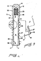
- Figure 3 is a cross-sectional side view of a second embodiment of the plug used in the plugging apparatus of the invention; and
- Figure 4 is an enlarged view of the circled portion of the plug wall illustrated in Figure 2 as it appears in sealing engagement with the inner wall of a tube.
- With reference now to Figures 1A and 1B, wherein like reference numerals designate like components throughout all the several figures, the tube plugging apparatus 1 of the invention is particularly adapted for plugging Inconel@ tubes 3 mounted in the
tubesheets 4 of nuclear steam generators. Generally speaking, the plugging apparatus 1 comprises aplug 5 having a concentrically disposedcavity 6, and anexpansion assembly 7 that is connected to a source of pressurized fluid and which has a hydraulically operated pull-rod mechanism 8 for applying both a radially expansive force and a compressive force on theplug 5. - With reference now to Figures 1A, 2 and 3, the
plug 5 of the invention is formed from a generally tubular shell 11 having a distalclosed end 12 that terminates in awall 13 whose outer surface is circumscribed by achamber 14, and a proximalopen end 15 having acircular opening 16 circumscribed by a flatannular wall 17. In both of the embodiments of the plug illustrated in Figures 2 and 3, respectively, the proximal end of thecavity 6 terminates in thecircular opening 16, while the distal end 21 of thiscavity 6 terminates at the inner surface of thewall 13. Additionally, the distal cavity ends 21 of both of the plug embodiments are surrounded by a plurality ofthreads 23 for engagement with a pull-rod member that will be described hereinafter. - Both of the plug embodiments illustrated in Figures 2 and 3 further include a tubular
middle portion 25 where theshell wall 27 is relatively thin with respect to the flanking walls. The exterior of themiddle portion wall 27 is circumscribed by six, equidistantly spaced lands 29, each of which includes a taperedouter edge 31. Themiddle portion wall 27 is flanked by thicker distal andproximal wall sections thicker wall sections section sections plug 5. Each of the taperedsections inner edge thinner wall 27 of themiddle portion 25, as well as anouter edge thicker wall sections plug 5, respectively. - The principal structural difference between the plug illustrated in Figure 2 and the plug illustrated in Figure 3 is that the
cavity 6 of the Figure 3 embodiment is formed by a "bottle bore" rather than from a cylindrically shaped bore. The bottle bore has the effect of tapering thewall portions plug 5, rather than from the outside, as is the case in the Figure 2 embodiment. Finally, the Figure 3 embodiment is somewhat shorter along its longitudinal axis than the Figure 2 embodiment. There are structural advantages associated with each embodiment. The Figure 2 embodiment is the easiest to manufacture, since thecavity 6 andcircular opening 16 are formed by a simple, cylindrical bore. However, since thetapered sections lands 29 must be manufactured with a fairly large radial extent relative to the outer surface of themiddle portion 25 of theplug 6 if they are to engage the inner wall of thetube 3 at the end of the expansion operation. The Figure 3 embodiment solves the need for manufacturing such radially long lands by providing the requiredtapered sections plug 5, neither embodiment is strongly preferred over the other. - With reference again to Figure 1A, the pull-
rod mechanism 8 of theexpansion assembly 7 includes a pull-rod member 52 having adistal shaft 54 that is integrally and concentrically connected with a relatively thickerproximal shaft 55 at joint 59. Anannular piston face 60 is defined around the upper end of the joint 59. This piston face 60 generates and applies a tensile force on the distal shaft 54whenever pressurized hydraulic fluid is applied thereto. Since theexpansion assembly 7 is designed so that thepiston face 60 communicates with the pressurized fluid injected into thecavity 6 of theplug 5, the provision of thepiston face 60 is a highly advantageous feature, since it obviates the need for a separate hydraulic ram to apply a tensile force on the pull-rod member 52. The narrowdistal shaft 54 of the pull-rod member terminates in a plurality ofthreads 56 which are matable with thethreads 23 present around the distal end of thecavity 6 in each embodiment of theplug 5. Thedistal shaft 54 of the pull-rod member 52 has a smaller outer diameter than the inner diameter of thecavity 6 in each embodiment of theplug 5, so that anannular space 57 is defined between the outer surface of thedistal shaft 54 and the inner surface of thecavity 6 whenever the pull-rod member 52 and a plug are threadedly mated in the manner illustrated in Figure 1A. Thisannular space 57 conducts pressurized hydraulic fluid into thecavity 6 in order that the tubularmiddle portion 25 of theplug 5 may be expanded into seating engagement with the inner walls of atube 3. The bottom end of theproximal shaft 55 terminates in asquare end 61 that is receivable within the socket of a wrench (not shown) when it becomes necessary to unscrew the threadedend 56 of the pull-rod member 52 from thethreads 23 of theplug 5. - The pull-rod member 52 of the pull-
rod mechanism 8 is slidably housed within aninlet block 62. Thisinlet block 62 includes a vertically disposed, telescoping bore 64 having aproximal bore section 66 that slidably receives the relatively narrowerdistal shaft 54 of the pull-rod member 52. Anannular shoulder 70 is defined at the top of thebore section 66 that limits the extent to which thepiston face 60 of the pull-rod member 52 can slide in the vertical direction within theblock 62. The bottom of thebore section 66 terminates in an enlarged threadedsection 67. In order to encourage a flow of hydraulic fluid into theannular space 57 defined within theplug 5 by thedistal shaft 54, the outer diameter of thedistal bore section 68 is deliberately made larger than the outer diameter of thedistal shaft 54. By contrast, only a minimum amount of clearance is provided between the outer diameter of theproximal shaft 55 and the inner surface of theproximal bore section 66 in order to discourage the flow of hydraulic fluid out of the bottom of theinlet block 62. To prevent any hydraulic fluid which does manage to flow through the small clearance between theproximal shaft 55 and boresection 66, aurethane sealing ring 72 is provided at the lower end of theinlet block 62. Thisring 72 forms a seal between theproximal shaft 55 and theproximal bore section 66 without interfering with the sliding movement of the pull-rod member 52 through theblock 62. To provide a tight and reliable seal, theurethane ring 72 is compressed into sealing engagement around theproximal shaft 55 by asteel compression ring 74. Thering 74 is in turn held in place by a threadedcollar 76 that is screwed into the enlarged, threadedportion 67 of thebore section 66. The threaded collar includeswrench flats 78 along its bottom sides to facilitate the assembly and disassembly of theexpansion assembly 7. - A laterally disposed inlet bore 80 is also provided in the
inlet block 62. The left end of this bore 80 conducts pressurized hydraulic fluid upwardly to theannular space 57 between thedistal shaft 54 of the pull-rod member 52 and thecavity 6 of theplug 5, and downwardly over theannular shoulder 70 and against thepiston face 60. The right end of thebore 80 terminates in an enlarged, threadedend 82 for receiving a fluid-tight fitting (not shown) that connects theblock 62 to a source of pressurizedhydraulic fluid 83. In the preferred embodiment, the source of hydraulic fluid is Hydroswage@ brand hydraulic expander manufactured by Haskel, Inc. of Burbank, California, USA. On the top surface of theblock 62, the terminal end of thedistal bore section 68 is surrounded by an integrally formed sealingring 84. The outer diameter of the sealingring 84 is smaller than the inner diameter of thetube 3, and the height of thering 84 is at least 3.175 millimeters (one-eighth of an inch). During the expansion operation, the annularupper surface 86 of the sealingring 84 engages the flatannular wall 17 of the plug. In order to render this engagement fluid-tight, an O-ring 88 is seated in anannular groove 90 that circumscribes the annularupper surface 86 of thering 84. Theannular groove 90 not only seats the 0-ring 88, but prevents it from blowing out during the expansion operation. - In the method of the invention, a
plug 5 is mounted onto the pull-rod member 52 of theexpansion assembly 7 by manually inserting thedistal shaft end 54 of the rod 52 into the proximalopen end 15, and screwing thethreads plug 5 is thus screwed into the pull-rod member 52, the flatannular wall 17 at the bottom of theplug 5 sealingly engages the top of the O-ring 88 located on thetop surface 86 of thering 84. Next, to enhance the seal between the 0-ring 88 and the flatannular wall 17 of theplug 5, a pre-load tensile sealing force of between 1 kilonewtons (300 pounds-force) and 2 kilonewtons (500 pounds-force) is applied to the pull-rod member 52 by introducing relatively low pressure hydraulic fluid into the lateral bore 80. This pressurized fluid flows downwardly against thepiston face 60, where it applies a hydraulically pushing force to the pull-rod member 52. This hydraulic force in turn causes thedistal shaft 54 of the member 52 to apply a compressive force to theplug 5 that securely seats its flat annular bottom 17 tightly against the O-ring 88. Of course, some of the hydraulic fluid also flows in theannular space 57 between theproximal shaft 54 and theplug cavity 6. However, the pressure at this time is not great enough to create any significant radial expansion in theplug 5. - If the
plug 5 proceeds through the pre-loading step without leaking, the operator of the apparatus next inserts theplug 5 into the open end of atube 3, and intensifies the pressure of the fluid until the shell 11 of theplug 5 is radially expanded. In the case of aplug 5 formed from Inconel• and having a diameter of about 11.176 millimeters (0.440 inches), such pressure amounts to about 193 megapascals (28,000 pounds per square inch). The application of such pressure to theinlet block 62 creates both a radially expansive force within theplug cavity 6 that is large enough to cause it to expand, as well as a tensile force of about 76 kilonewtons (1,700 pounds-force) on the pull-rod member 52. - The combination of the radially expansive force provided by the hydraulic fluid and the compressive force applied by the pull-rod member 52 has four desirable effects on the
plug 5. First, the radially expansive force expands the relatively thin-walled tubular portion 25 of the plug outwardly until thelands 29 forcefully and sealingly engage the inner wall of thetube 5, while the compressive force applied by the' pull-rod member 52 inelastically deforms themiddle portion 25 of theplug 5 into this sealing position. The compressive force permanently deforms themiddle portion 25 into this radially expanded position by providing a controlled buckling of the walls at the juncture between thetapered portions plug 5, and the distal and proximal edges of the relatively thin-walledmiddle portion 25 of theplug 5. The precise shape of this buckling is evident in Figure 1 B, as well as the attendant shortening of theplug 5 along its longitudinal axis. This controlled buckling along the longitudinal axis of theplug 5 counteracts the tendency of the radially expandedmiddle portion 25 of the plug to "spring back" after the pressurized fluid is relieved from theannular space 57 defined between the pull-rod member 52, and the inner surface of the thin-walledmiddle portion 25. The second advantageous effect from the joint application of a compressive and radially expansive force on theplug 5 is the fact that the compressive force sealingly engages theannular face 17 of theplug 5 even more tightly against the O-ring 88 located on theupper surface 86 of theseating ring 84, thereby obviating the need for any sort of complex mechanism to contain the 193 megapascals (28,000 pounds per square inch) pressure within thecavity 6 of theplug 5 during the plugging operation. The third advantageous effect is that the compressive force applied by the pull-rod member 52 more than counteracts the net upwardly directed force that the hydraulic fluid applies onto theplug 5, thereby holding it in a completely stationary position throughout the entire plugging operation. The fourth and final positive effect is best understood with respect to Figure 4. The radially expansive force within thecavity 6 of theplug 5 is sufficient to force the taperededges 31 of thelands 29 into the inner walls of thetube 3 during the plugging operation. After the radial and compressive forces are relieved from theplug 5, the Inconel@ that forms theplug 5 will tend to "spring back" slightly along its longitudinal axis. This longitudinal spring back will cause the tapered ends 31 of thelands 29 to very tightly engage one of the sides of the slight notch that thelands 29 form by their forceful engagement of the wall of the tube 3 (see circled portions). While applicant has not completely confirmed this beneficial effect of the method of the invention, applicant has reason to believe at the time of the filing of this application that the invention exploits the longitudinal spring back of theplug 5 to create extremely tight sealing surfaces along the upper edges of theupper lands 29 as shown in Figure 4, and along the lower edges of the lower lands 29 (not shown). - After both the hydraulic and the tensile forces are relieved by admitting the pressurized fluid out of the
inlet block 62, the pull-rod member 52 is detached from the distal end of thecavity 6 of theplug 5 by grasping thesquare end 62 of the member 52 with a wrench, and unscrewing the threadedend 56 of the member 52 from thethreads 23 within theplug 5. During the final plugging step, it is important to note that no part of theinlet block 62 of theexpansion assembly 7 should be placed against either the bottom edge of thetube 3 or thetubesheet 4 when the fluid pressure is intensified to 193 megapascals (28,000 pounds per square inch). If the top of theblock 62 were so positioned, the longitudinal spring-back of theplug 5 could cause galling to occur between thelands 29 and the inner walls of thetube 3, thereby jeopardizing the integrity of the seal. - While the preferred embodiment has been described in the context of a nuclear steam generator, the plug of the invention may be used to plug most any tube in any environment, and is particularly well suited to plug the heat exchange tubes in the tubesheets of fossil fuel power plants.
Claims (6)
Applications Claiming Priority (2)
| Application Number | Priority Date | Filing Date | Title |
|---|---|---|---|
| US93655986A | 1986-12-01 | 1986-12-01 | |
| US936559 | 1986-12-01 |
Publications (2)
| Publication Number | Publication Date |
|---|---|
| EP0270053A1 EP0270053A1 (en) | 1988-06-08 |
| EP0270053B1 true EP0270053B1 (en) | 1991-01-23 |
Family
ID=25468806
Family Applications (1)
| Application Number | Title | Priority Date | Filing Date |
|---|---|---|---|
| EP87117681A Expired - Lifetime EP0270053B1 (en) | 1986-12-01 | 1987-11-30 | Apparatus and method for plugging a tube |
Country Status (4)
| Country | Link |
|---|---|
| EP (1) | EP0270053B1 (en) |
| JP (1) | JPS63143496A (en) |
| DE (1) | DE3767679D1 (en) |
| ES (1) | ES2020256B3 (en) |
Families Citing this family (2)
| Publication number | Priority date | Publication date | Assignee | Title |
|---|---|---|---|---|
| NL1007976C2 (en) * | 1998-01-07 | 1999-07-08 | Metaalgieterij Giesen B V | Method and sealing plug for sealing a core hole in a casting. |
| JP5594210B2 (en) * | 2011-03-29 | 2014-09-24 | 三菱マテリアル株式会社 | Manufacturing method of head exchangeable cutting tool, and connecting member used in the manufacturing method |
Family Cites Families (7)
| Publication number | Priority date | Publication date | Assignee | Title |
|---|---|---|---|---|
| US3525365A (en) * | 1966-10-17 | 1970-08-25 | Pneumo Dynamics Corp | Expansion plug |
| DE3166591D1 (en) * | 1980-07-30 | 1984-11-15 | Westinghouse Electric Corp | Tube plug |
| US4393564A (en) * | 1980-12-08 | 1983-07-19 | Martin John E | Method and apparatus for repairing heat exchangers |
| US4369662A (en) * | 1981-02-25 | 1983-01-25 | Westinghouse Electric Corp. | Plug installation apparatus |
| JPS5851023A (en) * | 1981-08-31 | 1983-03-25 | ウエスチングハウス・エレクトリツク・コ−ポレ−シヨン | Fixing of metal sleeve |
| US4436117A (en) * | 1982-12-02 | 1984-03-13 | Martin John E | Leak resistant plug assembly |
| US4485847A (en) * | 1983-03-21 | 1984-12-04 | Combustion Engineering, Inc. | Compression sleeve tube repair |
-
1987
- 1987-11-30 ES ES87117681T patent/ES2020256B3/en not_active Expired - Lifetime
- 1987-11-30 EP EP87117681A patent/EP0270053B1/en not_active Expired - Lifetime
- 1987-11-30 DE DE8787117681T patent/DE3767679D1/en not_active Expired - Lifetime
- 1987-12-01 JP JP62301663A patent/JPS63143496A/en active Pending
Also Published As
| Publication number | Publication date |
|---|---|
| DE3767679D1 (en) | 1991-02-28 |
| ES2020256B3 (en) | 1991-08-01 |
| JPS63143496A (en) | 1988-06-15 |
| EP0270053A1 (en) | 1988-06-08 |
Similar Documents
| Publication | Publication Date | Title |
|---|---|---|
| US4655483A (en) | Boundary seal for vessel penetration | |
| US4485847A (en) | Compression sleeve tube repair | |
| US4436117A (en) | Leak resistant plug assembly | |
| US4069573A (en) | Method of securing a sleeve within a tube | |
| US4787420A (en) | Plugging apparatus and method using a hydraulically assisted plug expander | |
| US4366617A (en) | Plug removal apparatus | |
| JPH0428996B2 (en) | ||
| US4771810A (en) | Multi-seal mechanical tube plug | |
| US4831703A (en) | Apparatus and method for plugging a tube | |
| CA1326128C (en) | Method of apparatus for expanding and sealing a sleeve into a surrounding tube | |
| US5194214A (en) | Tube plug and method for plugging a tube | |
| US3215166A (en) | Flanged joint for pipes | |
| US4986313A (en) | Sealing plug for a steam-generator tube | |
| US4761981A (en) | Swaging apparatus for flaring and anchoring tubes | |
| US4765374A (en) | Multi-seal mechanical tube plug | |
| US5456290A (en) | Tube plug having a flange sealing a chamber for plugging a tubular member | |
| JPS6056427A (en) | Expanding device for pipe or sleeve in pipe | |
| EP0270053A1 (en) | Apparatus and method for plugging a tube | |
| US4512496A (en) | High pressure feedwater heater closure assembly | |
| US20260011459A1 (en) | Closures for pressure vessels, and associated systems and methods | |
| US4779333A (en) | Sleeve to tubesheet expander tool | |
| US4445261A (en) | Method for installing tubes in a tube sheet | |
| EP0044982B1 (en) | Tube plug | |
| EP0137984A2 (en) | Tube repair insert for steam generator | |
| US4607426A (en) | Swaging method and apparatus for axially extended expansion of tubes |
Legal Events
| Date | Code | Title | Description |
|---|---|---|---|
| PUAI | Public reference made under article 153(3) epc to a published international application that has entered the european phase |
Free format text: ORIGINAL CODE: 0009012 |
|
| AK | Designated contracting states |
Kind code of ref document: A1 Designated state(s): BE CH DE ES FR GB IT LI SE |
|
| 17P | Request for examination filed |
Effective date: 19881118 |
|
| 17Q | First examination report despatched |
Effective date: 19890810 |
|
| GRAA | (expected) grant |
Free format text: ORIGINAL CODE: 0009210 |
|
| ITF | It: translation for a ep patent filed | ||
| PGFP | Annual fee paid to national office [announced via postgrant information from national office to epo] |
Ref country code: FR Payment date: 19910121 Year of fee payment: 5 |
|
| AK | Designated contracting states |
Kind code of ref document: B1 Designated state(s): BE CH DE ES FR GB IT LI SE |
|
| ET | Fr: translation filed | ||
| REF | Corresponds to: |
Ref document number: 3767679 Country of ref document: DE Date of ref document: 19910228 |
|
| PGFP | Annual fee paid to national office [announced via postgrant information from national office to epo] |
Ref country code: BE Payment date: 19910619 Year of fee payment: 5 |
|
| PGFP | Annual fee paid to national office [announced via postgrant information from national office to epo] |
Ref country code: DE Payment date: 19910917 Year of fee payment: 5 Ref country code: CH Payment date: 19910917 Year of fee payment: 5 |
|
| PGFP | Annual fee paid to national office [announced via postgrant information from national office to epo] |
Ref country code: GB Payment date: 19910918 Year of fee payment: 5 |
|
| PGFP | Annual fee paid to national office [announced via postgrant information from national office to epo] |
Ref country code: SE Payment date: 19911114 Year of fee payment: 5 |
|
| PGFP | Annual fee paid to national office [announced via postgrant information from national office to epo] |
Ref country code: ES Payment date: 19911115 Year of fee payment: 5 |
|
| PLBE | No opposition filed within time limit |
Free format text: ORIGINAL CODE: 0009261 |
|
| STAA | Information on the status of an ep patent application or granted ep patent |
Free format text: STATUS: NO OPPOSITION FILED WITHIN TIME LIMIT |
|
| 26N | No opposition filed | ||
| PG25 | Lapsed in a contracting state [announced via postgrant information from national office to epo] |
Ref country code: LI Effective date: 19921130 Ref country code: GB Effective date: 19921130 Ref country code: CH Effective date: 19921130 Ref country code: BE Effective date: 19921130 |
|
| PG25 | Lapsed in a contracting state [announced via postgrant information from national office to epo] |
Ref country code: SE Effective date: 19921201 Ref country code: ES Free format text: LAPSE BECAUSE OF THE APPLICANT RENOUNCES Effective date: 19921201 |
|
| BERE | Be: lapsed |
Owner name: WESTINGHOUSE ELECTRIC CORP. Effective date: 19921130 |
|
| GBPC | Gb: european patent ceased through non-payment of renewal fee |
Effective date: 19921130 |
|
| PG25 | Lapsed in a contracting state [announced via postgrant information from national office to epo] |
Ref country code: FR Effective date: 19930730 |
|
| REG | Reference to a national code |
Ref country code: CH Ref legal event code: PL |
|
| PG25 | Lapsed in a contracting state [announced via postgrant information from national office to epo] |
Ref country code: DE Effective date: 19930803 |
|
| REG | Reference to a national code |
Ref country code: FR Ref legal event code: ST |
|
| EUG | Se: european patent has lapsed |
Ref document number: 87117681.4 Effective date: 19930709 |
|
| REG | Reference to a national code |
Ref country code: ES Ref legal event code: FD2A Effective date: 20010402 |
|
| PG25 | Lapsed in a contracting state [announced via postgrant information from national office to epo] |
Ref country code: IT Free format text: LAPSE BECAUSE OF NON-PAYMENT OF DUE FEES;WARNING: LAPSES OF ITALIAN PATENTS WITH EFFECTIVE DATE BEFORE 2007 MAY HAVE OCCURRED AT ANY TIME BEFORE 2007. THE CORRECT EFFECTIVE DATE MAY BE DIFFERENT FROM THE ONE RECORDED. Effective date: 20051130 |