EP0269680B1 - Patient controlled device for ajusting a hearing aid, method, and test device for such a hearing aid - Google Patents
Patient controlled device for ajusting a hearing aid, method, and test device for such a hearing aid Download PDFInfo
- Publication number
- EP0269680B1 EP0269680B1 EP87903646A EP87903646A EP0269680B1 EP 0269680 B1 EP0269680 B1 EP 0269680B1 EP 87903646 A EP87903646 A EP 87903646A EP 87903646 A EP87903646 A EP 87903646A EP 0269680 B1 EP0269680 B1 EP 0269680B1
- Authority
- EP
- European Patent Office
- Prior art keywords
- patient
- sound
- hearing aid
- response characteristics
- electronic components
- Prior art date
- Legal status (The legal status is an assumption and is not a legal conclusion. Google has not performed a legal analysis and makes no representation as to the accuracy of the status listed.)
- Expired - Lifetime
Links
Images




Classifications
-
- H—ELECTRICITY
- H04—ELECTRIC COMMUNICATION TECHNIQUE
- H04R—LOUDSPEAKERS, MICROPHONES, GRAMOPHONE PICK-UPS OR LIKE ACOUSTIC ELECTROMECHANICAL TRANSDUCERS; ELECTRIC HEARING AIDS; PUBLIC ADDRESS SYSTEMS
- H04R25/00—Electric hearing aids
- H04R25/70—Adaptation of deaf aid to hearing loss, e.g. initial electronic fitting
-
- A—HUMAN NECESSITIES
- A61—MEDICAL OR VETERINARY SCIENCE; HYGIENE
- A61B—DIAGNOSIS; SURGERY; IDENTIFICATION
- A61B5/00—Measuring for diagnostic purposes; Identification of persons
- A61B5/12—Audiometering
-
- H—ELECTRICITY
- H04—ELECTRIC COMMUNICATION TECHNIQUE
- H04R—LOUDSPEAKERS, MICROPHONES, GRAMOPHONE PICK-UPS OR LIKE ACOUSTIC ELECTROMECHANICAL TRANSDUCERS; ELECTRIC HEARING AIDS; PUBLIC ADDRESS SYSTEMS
- H04R25/00—Electric hearing aids
- H04R25/75—Electric tinnitus maskers providing an auditory perception
Definitions
- the invention relates to testing devices used to select a hearing aid prosthesis. More particulary, the invention comprises a device which is connected to a test module placed in a patient's ear to selectively combine various electronic components used in the design of a hearing aid. Using the device, the patient may select those electronic components which combine to yield amplification which best assists the patient's hearing loss or hearing impediment so that a patient selected hearing aid may be provided which the patient has identified as being most preferred for the patient's unique hearing characteristics and defects.
- Hearing aids have been prescribed and provided in the past based on the results of audiometric testing procedures which include hearing threshold tests wherein various sinusoidal tones of differing frequency are transmitted through a set of headphones and patient indicates at which lowest level the sound is first detectable.
- the professional charts or plots the results of the acuity or threshold testing on an "audiogram” and evaluates the hearing loss within the context of conventional hearing standards and norms.
- One of many currently popular (and often disparate) fitting philosophies is then employed to "prescribe" the performance characteristics of a hearing aid which the professional believes will effectively amplify those sound frequencies which the test results indicate deviate from the norm.
- the audiogram and an impression of the patient's ear are sent to a hearing aid manufacturer and a design technician assumes the responsibility for prescribing a circuit for the device.
- the electroacoustic characteristics of headsets or earphones conventionally used in audiometric testing or previous master hearing aid simulators are usually substantially different from those of the miniaturized receivers used in hearing aids, thereby rendering predictions and prescriptions of appropriate frequency response between systems employing different types of transducers quite difficult and unreliable.
- Attempts to predict and prescribe meaningful and effective hearing aid fittings with headphone equipped instrumentation are further confounded by the fact that the sound output of a hearing aid is altered by the resonant characteristics of the individual's own ear canal, along with a variety of other acoustic effects which arise from the interplay between the hearing aid and such factors as canal insertion depth, ear geometry, frequencies in the amplified signal, standing waves and the impedance of the eardrum.
- These same phenomena also render recent efforts to use miniature microphones for in-situ (i.e., in the canal) measurement of hearing aid characteristics in the prescription and fitting process prone to error.
- This system includes a speaker for presenting test and environmental sounds to the patient, an earshell assembly to be placed in the patient's ear canal, a test module connected to the earshell assembly to pass the sounds, in the form of sound response characteristics corresponding to a particular hearing aid, through the test module adjacent the patient's ear drum, a patient console connected to the test module via a host computer, and an operator's console for controlling the computer so that predetermined sounds are presented to the patient.
- the patient's input in adjusting the hearing aid is limited to fine tuning adjustments.
- US-A-3,784,750 further describes a system for providing electronic correction of auditory deficiencies and provides a hearing aid having an amplifier that includes a filter network permitting adjustment of amplitude for each of a plurality of frequency passbands to permit approximation of a desired overall response curve, to improve speech recognition.
- the patient adjusts a number of filter controls in response to recorded speech so that, at the completion of the test, a desired amplification for certain bandpass frequencies has been chosen.
- What has been lacking in the prior attempts to create a master hearing aid testing apparatus is a device which permits the patient to be an intimate and important part of the selection process. It is necessary that the patient communicate his or her amplification preferences fully during the testing process. The patient must then be able to receive a hearing aid which matches as closely as possible the sound quality and other performance characteristics which were preferred during the evaluation.
- the patient controlled master aid of the instant invention is a fully integrated apparatus which allows the patient to be the primary decision maker in the selection process of the prescription for the hearing aid that will be provided.
- the patient initially selects an earshell assembly which comfortably and accurately conforms to the patient's own ear canal, both to the diameter of the ear canal and to the specific geometry of the patient's ear canal.
- This earshell assembly is the earshell assembly that is used during the testing process and is also the earshell assembly that will be used for the patient's hearing aid. Therefore, resonant and other acoustic characteristics of the patient's ear canal are addressed and become part of the testing process.
- test module is then inserted into the earshell assembly which employs one or more receivers and microphones , used to provide a variety of hearing aid response characteristics.
- One of these microphones will be selected and will have the same manufacturer's specifications as the microphone that will actually be used in the patient's hearing aid.
- These test module transducers are connected by a cable to the patient's console.
- Two microprocessor based test consoles are provided, one for the patient and one for the tester.
- One function of the operator's console is to establish sound field test conditions which simulate as closely as possible the patient's listening experience in the patient's own environment.
- Tape decks are provided for the presentation of a "target stimulus” (e.g., continuous discourse) and environmental "ambience” (e.g., background noise or competing speech signals).
- Outputs from the tape decks are electronically mixed and preferably provided in a multiphonic sound field around the patient, that is, with sound emanating toward the patient from many directions.
- S.S.P.L. saturation sound pressure level
- Gain is defined to be the peak acoustic gain with 60 dB SPL input over the entire frequency range.
- Slope is defined as the difference between the acoustic gain at 500 Hz and the peak gain.
- the electronic components which establish the maximum or saturation sound pressure level of the aid, the amplification gain of the aid and the slope of the frequency response of the aid are presented to the patient in a paired comparison, decision tree format.
- the decision tree can be automatically presented under microcomputer control or can be manually presented by the tester from the operator's console.
- Two parameters are initially set or fixed and the patient steps through choices of the third parameter, indicating the preferred sound quality which best assists the hearing loss. That parameter and one of the remaining parameters are then set and fixed and the patient comparatively evaluates the second variable parameter.
- the patient's choices are indicated by touching one of two switch panels on the patient's console indicating, for example, whether minimum or maximum low frequency emphasis amplification is preferred within a sound field of "target-stimuli” and environmental "ambience” which emanate from the speakers that surround the patient.
- the first two selected parameters are fixed and the patient selects the third parameter based on the previously selected conditions. Because of the ease with which the decision tree can be pursued, the test may be repeated a number of times with a different first parameter being selected for each of the sequence of tests. If a different sequence produces a slightly different result, the two selections can be compared in tournament fashion so that the best sound response can be selected by the patient.
- circuit elements that establish the sound pressure level, the gain and the slope during the testing process including the microphone, amplifier and receiver, are the same circuit elements or have the same specifications as those that will be provided in the final hearing aid selected by the patient.
- an amplification module is provided by the dispenser having the same electronic components that the patient selected during testing. That amplification module is snapped into the earshell assembly which the patient selected prior to testing and the patient may leave the premises with the same hearing aid that the patient has chosen during the testing process.
- Figure 1 is a graphic representation of the testing environment in which the patient is positioned within a quadraphonic sound field and is provided with a test module in an earshell assembly connected to a patient console which is interconnected to an operator's console for purposes of the test.
- Figure 2 is a representation of the operator's console showing the controls which the dispenser manipulates to establish the test conditions.
- Figure 3 is a representation of the patient's console which the patient utilizes to comparatively choose the sound characteristics of a hearing aid which best addresses the patient's hearing impediment.
- Figure 4 consisting of Figures 4a-4f, show the various components used in the earshell assembly and test module which is fit in the patient's ear for purposes of the testing.
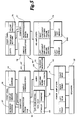
- FIG. 5 is a block diagram of the modules or boards used in the operator's or master console and the patient or subject console.
- Figure 6 is a schematic diagram of the electronic components which are used in the hearing aid which is produced as a result of testing by the patient controlled master aid.
- Figure 7 is a family of matrix curves for an established S.S.P.L. and gain showing possible variations in slope which affect low frequency roll-off.
- Figure 8 is a similar family of matrix curves having a fixed saturation sound pressure level and fixed slope showing variations in gain.
- Figure 9 is a family of matrix curve showing a fixed gain and a fixed slope showing changes in saturation sound pressure level.
- Figure 10 consisting of Figures 10a, 10b and 10c, shows a representative decision tree which may be controlled by the operator of the master console or automatically by software.
- the patient is presented with a tournament of paired comparison choices from which the preferred S.S.P.L., gain and slope must be selected from the available electronic circuit component combinations.
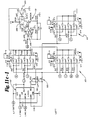
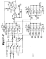
- Figure 11 consisting of Figures 11a - 11c, are schematic drawings of circuits which are used to select electronic components which will be matched by the electronic components of the final aid.
- the first essential element is that the burden of hearing aid selection should be shouldered more fully by the hearing impaired listener through the use of valid and effective psychoacoustic tasks.
- the second essential element proposed was that there be precise and accurate correspondence between the sound which the listener preferred during amplification selection and the sound delivered by the hearing aid he or she received.
- the instant invention is based on that proposal and achieves those two essential elements.
- the patient Prior to employing the apparatus of this invention to provide a hearing aid it is preferred that the patient undergo a thorough medical and audiometric evaluation to be sure that amplification is the appropriate course of action and the patient is a candidate for a hearing aid. It is preferred that the cause and source of any hearing impediment whether it be tinnitus or a hearing loss be thoroughly medically evaluated as to both its source and possible medical solution before the impediment is adjudged permanent and appropriate for a hearing aid or masking sound source of the type proposed. Hearing problems can also be the result of other and more severe medical problems which should and must be addressed.
- the instant invention is designed for use by a dispenser in conjunction with the patient to select a hearing aid to specifically help the patient in overcoming the handicapping aspects of the loss or condition.
- Figure 1 shows a preferred test arrangement to enable the patient to comparatively select the proper electronic components 60 to be utilized in the patient's hearing aid so that the aid has those amplification characteristics which the patient prefers.
- the patient is preferably situated in a sound field listening environment such as that shown in Figure 1 with a plurality of speakers 22 arrayed around the patient's head so that the natural hearing environment in which the aid is to used can be recreated.
- the speaker array is situated so that the physical design and natural acoustic characteristics of the head and human hearing mechanism are fully utilized during the evaluation. These factors include the sound diffractive attributes of the head, the gathering and funneling of sound into the ear canal by the Pinna, and the multiple sound reflections produced by the crenulations of the Pinna.
- the signals arriving at the ears encompass these phenomena and provide the brain with differential time and intensity sound cues which assist a listener in discerning the nature, direction, and distance of sound sources.
- test module or assembly 200 which is shown in Figure 4 having two microphones 210, 212 and a receiver 220 and connected by an umbilical cord 203 to the patient console 45 is inserted into the hearing aid earshell 12.
- the acoustical properties of the earshell assembly 12 will not vary between the test and the actual use of the aid.
- FIG 4a Shown in Figure 4a, is a representation of an earshell assembly 12 with a distinctive forward and inward hook and an upward twist.
- One of five standardized earshell coverings 30a-30e is employed, the covering being soft and malleable, to seal to the skin of the ear canal and to conform to the geometry of the canal.
- a test module 200 having a combined hearing aid speaker 220 and two cushioned selectable microphones 210, 212 interconnected by a flexible substrate 216 shown in Figures 4c and 4d are mounted in a removable cover 201 module shown in Figure 4b.
- the microphones 210, 212 extend through the apertures 202, 204 in the cover 201 and the cover 201 is detachably retained by the flange 40 of earshell assembly 12 and collar segments 244, 246.
- the six leads 250-255 to and from the receiver 220 and microphones 210, 212 are connected to the umbilical cord 203 from the top of the test cover module 200.
- both microphones 210, 212 can be electronically disconnected to make them non-operable and a random noise generator connected to the amplifier 220 for purposes of tinnitus masking.
- the test module 200 is snapped into the earshell 12 and the assembly 12 is placed in the patient's ear.
- Components determining electrical characteristics are set to initial values and sound stimuli and ambience presented through the speakers 22.
- the patient can then be asked to choose one of a plurality of vent inserts 134a-134e shown in Figures 4c and 4d. Venting of air from the environment to the eardrum avoids a plugged feeling of the ear and also serves a variety of acoustic functions.
- the patient selectable size of the vent aperture 133b-133e can, for example, be used to enhance or reduce low frequency sound energy such as may be contained in environmental noise.
- the master console includes electronic circuit modules for the front panel displays 55 and controls 57, a microcomputer 59 for control and communications 63 between the master console 50 and the subject console 45, and a stimulus and ambience tape deck 65, 66 to produce the environmental sound field. Both tape decks 65, 66 are connected to an audio board 69 which switches and mixes the sound which is connected to power amplifiers 71 for each of the four speakers 22 utilized which are shown in Figure 1. In addition a talk-over microphone 73 is provided in the master console 50 connected to the audio circuits 69 so that the tester can communicate with the subject or patient.
- These electronic circuits are of substantially conventional design and any suitable circuit may be employed which permits the objectives of the invention to be achieved.
- the speaker 22 level controls 81-88 can be varied to simulate a variety of three dimensional sound effects such as noise entering an open window in a car, shouts coming from ahead of, behind of or either side of the patient, radio music as the primary sound source or as background noise, telephone conversations or to simulate any other imaginable sound environment in which the patient may find himself or herself.
- the patient's console 45 Interconnected to the operator's console 50 by an eight-conductor cable 47 is the patient's console 45 with four functional circuit modules.
- the front panel circuits 76-79 operate the patient accessible controls which include two variously colored light panels 92, 93, such as blue and orange, and a response mechanism 95, 96 for each to determine which of the light panels 92, 93 the patient has selected. Also shown in Figures 3 and 5 are the response buttons 95, 96 and separate right and left volume controls 98, 99 which the patient may rotate to adjust the gain or volume level of the aid when a hearing aid is being provided.
- a similar conventional microcomputer system 77 consisting of a microprocessor and ROM and RAM memories with a communication module 78 is used to inter-connect the subject console 45 to the master console 50.
- hearing aid amplifiers 79 which are connected to the microphones and receiver which are located in the earshell assembly, and which include the integrated circuit amplifier and the various resistive and capacitance components shown in Figure 11 which are used to establish various levels of S.S.P.L., gain and slope and separate volume controls for both right and left test modules 200.
- Both right and left test circuits 79 and modules 200 are provided so that the patient can individually test either ear and towards the end of testing have either or both test modules 200 in place while a final and complete check of the selected components is accomplished.
- Component selection and switching which is one of the more important aspects of the invention, is discussed in more detail below in connection with the schematic diagrams of the circuits in the subject console as shown in Figures 11a - 11d.
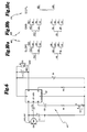
- FIG. 6 shows the electronic schematic of the final hearing aid.
- the components 60 of the hearing aid include a microphone 210 or 212 for a hearing aid or a pseudo-random noise generator 110 for a tinnitus masker, which is interconnected by resistors R1-R3 and capacitors C1-C4 through a hearing aid amplifier 112, manufacturers designation LS 505, manufactured by Linear Technology Incorporated.
- the amplifier 112 is also connected to a receiver 220 which provides the acoustic output of the hearing aid to the patient's eardrum.
- the microphone 210 or 212 and the input coupling capacitor C2 may be varied. Selecting different combinations of those two components as shown in Figure 10a, changes the low frequency roll-off.
- Two selectable microphones 210, 211 are provided, one with a fairly flat low frequency response and the other with a roll-off of the low frequency response.
- the selected microphone 210 or 211 in combination with the selected coupling capacitor C2 selects the aid's response to low frequency sounds.
- the selected capacitor C2 determines the low frequency response of a tinnitus masker when connected to a pseudo-random generator such as shown in Figure 11b.
- Gain is selected by the value of R1 in series with the volume control R2. Maximum gain is achieved at a low resistance for R1 and the volume control R2 and as resistance R1 is increased the gain of the aid is decreased. Variations of gain of the amplifier are shown in Figure 8 and a selection matrix is shown in Figure 10b.
- R3 selects the saturation sound pressure level of the aid.
- the saturation sound pressure level is the level of sound pressure that the aid cannot exceed, the level at which the amplifier saturates or reaches its maximum amplification. Two levels are shown in Figure 11c. It will be understood, however, that additional levels can be easily achieved.
- R1 there is interaction between the values selected for R1 and R3 which is accommodated by the test procedure.
- a maximum output level setting such as one hundred ten dB selected by R3
- the value used for a particular gain such as thirty dB will yield a resistance value of two thousand ohms for R1.
- R1 would be 1600 ohms.
- the hearing aid circuit includes the battery B-1 and capacitor C1, a bypass capacitor used to decouple the power supply battery B1 from the microphone supply.
- This capacitor C1 together with a resistor in the amplifier 112, provide low pass filter that decouples battery B1 voltage modulation from the microphone 210 or 211, effectively providing a slight increase in gain.
- the remaining capacitor, C4 is used to roll-off the high end of the output signal by effectively shorting out the very high end receiver frequencies.
- a target stimulus sound to which the patient is to respond such as continuous speech
- Background or environmental noise is combined with the target-stimulus with the mixing circuit in module 69.
- the stimulus sound is played from the first tape deck 65 while an ambience noise level is created with the second tape deck 66, both of which are presented simultaneously through the speakers 22.
- Separate stimulus and ambience level controls 120-127 are provided for each of the four speakers 22.
- Visual level indication is provided by LED displays 140-147 associated with each of the eight speaker level controls 120-128.
- Hearing aid gain or volume controls 162, 163 and 98, 99 are also provided for a right test module 200 and a left test module 200 on both the operator's console 50 and patient's console 45.
- the operator may override the patient's volume control 98 or 99 with the volume control 162 or 163 on the operator's console 50 if the patient is not using the volume control 98 or 99 correctly or is having difficulty or discomfort. It is important for the professional to monitor the patient preferred volume control settings to insure that they lie within the most useful, mid-range, rather than at either extreme of the control.
- Preferably two of the parameters are set by software or by the tester using the master console 50 at selected values and a third, the test parameter, is varied in a paired comparison tournament for selection by the patient.
- S.S.P.L. 170 and gain 168 be set at their maximum settings and slope 165 be varied for the patient selection.
- slope 165 is set at the patient preferred setting
- S.S.P.L. 170 is left at the high range setting and gain 168 is varied for patient selection.
- slope 165 and gain 168 are set at the patient selected setting and S.S.P.L. 170 is varied for the patient.
- Tinnitus testing is similar.
- the pseudo-random noise generator 110 is provided which connects through the amplifier 112 to the receiver 220.
- Additional displays 55, operator controls or switches 57 and the talkover microphone 73 are provided on the operator's console so that the operator can selectively monitor and/or perform the testing process.
- LED displays 175, 176, 177, 178 are provided to monitor the patient comparison selection, the present values of frequency response the output levels of the speakers 22 relative to the patient's head position and the volume control setting chosen by the patient which can be varied by the operator with switches 162, 163.
- S.S.P.L., gain, slope or tinnitus selection switches 180 are provided as well as a full range of switch controls 183, 185 for the tape decks 65, 66 and the right and left test modules 200.
- FIG. 10 a number of computer controlled input lines 300, 301 are provided for both the left module 200 and the right module 200.
- the circuitry is identical for both left and right test modules 200 and the circuitry for only one module will be explained, the left module, with the understanding that similar test provisions and circuits are provided and shown for the right module.
- Switching of components is accomplished with analog switches A-1 - A-4 which are activated by the computers 59, 73 upon appropriate command by the master console 30.
- two microphones 210, 212 may be provided in the test module 200, one of the microphones having a flat, low frequency response and the other microphone having a sloped low frequency response.
- Either microphone 210, 212 can be selected with an analog switch A11 or A12.
- a pseudo-random noise generator 110 as shown in Figure 12b, may be connected through analog switch A13 and utilized for tinnitus masking. All input sounds may also be disconnected and the signal source line grounded with an analog switch A14 for purposes of disabling the module 200.
- Coupled in series with the microphones 210, 212 and pseudo-random noise generator 110 are four coupling capacitors C17-C20, each of which can be connected either individually or in parallel by appropriate analog switches A2.
- Four slope levels are established, two for each selected microphone 210 or 212, to establish a patient preferred slope. Therefore, with gain 168 and S.S.P.L. 170 fixed at a selected setting, the patient can evaluate each of the four levels of slope 165 to determine the preferred low frequency response of the aid.
- Data is exchanged between the patient console 45 and operator's console 50 via a half-duplex serial communications channel 63, 47, 78 under microcomputer 59, 77 control.
- the operator's console 50 selects values of S.S.P.L. 170, gain 168 and slope 165, which it communicates to the patient's console 45.
- the computer 77 in the patient's console 45 using a look-up table, selects the components required.
- the operator's console 50 also selects which light 92 or 93 on the patient's console 45 is to be illuminated. To avoid introducing a bias during testing, there is no fixed correspondence between a particular set of parameters and a light color.
- the tester may initially implement a -30 dB slope 165a using MIC 2 and capacitor C20, concommitant with illuminating the orange light 92 on the patient console 45. Then a -15 dB slope 165d may be enabled using MIC 1 and capacitor C17 along with illumination of the blue light 93. The patient alternately listens to the frequency response at both slopes. Assuming the patient selects the -30 dB slope 165a as preferable and touches the response button 95 below the orange light 92, the sequence is repeated using first MIC 2 and capacitor C19 for a -20 dB slope 165b, then MIC 2 and capacitor C20 for a -30 dB slope 165a.
- the output of the coupling capacitor C17-C20 is connected to the microphone input of the LS 505 amplifier 112 which is shown in Figure 11c.
- gain selection resistors R9-R14 Connected to the gain input of the amplifier 112 are gain selection resistors R9-R14 which are selectably connectable either individually or in parallel, to the circuit by the microprocessor 77 through a series of analog switches A3.
- the gain selection resistors R9, R10 are switched through a pair of analog switches connected in parallel, A31, A32 and A33, A34 respectively. This serves to effectively cut the resistance of the analog switch A3 in half.
- the resistance values of the gain selection resistors R9-R14 are selected at a somewhat lower value (typically about 150 ohms less) than the design value of the corresponding resistor R1 in the hearing aid to compensate for the resistance of the analog switches A6 and the minimum resistance of the opto-isolated field-effect transistor (FET) U17 discussed below.
- a variable resistor 190 in series with the gain selection resistors R9-R14 is provided to further adjust the total resistance yielded by the variable resistor 190, gain selection resistor R9-R14, analog switch A6 and opto-isolated FET U17 so that is is equal to the design value for the hearing aid.
- the software or tester may again cycle the patient through the decision tree choices by presenting different gain pairs, for example 40 dB gain and 25 dB gain, and then 40 dB gain and 30 dB gain if the patient selects 40 dB gain (see figures 8 and 11b).
- the volume control R2 in the hearing aid is a variable resistor rather than a potentiometer or voltage divider. Maximum gain is reached with a volume control setting of zero ohms and increasing the volume control resistance R2 decreases the gain of the hearing aid.
- the volume control resistance is simulated electronically. As shown in the schematic, this is achieved with an opto-isolated field-effect transistor U17 operating as a variable resistor.
- the field-effect transistor 193 is operated in a linear range of the ratio between the input current to the LED 194 versus the resistance of the field-effect transistor 193. Values of the resistance are achieved with a digital-to-analog converter (not shown) with precise analog steps, ranging from zero to -10 volts.
- This output voltage is connected to operational amplifier U16 which is a voltage-to-current converter circuit with the use of transistor Q1.
- the current range through transistor Q1, and thus through the LED 194, is zero to sixteen milliamps which is modulated in discrete digital steps by the digital to analog circuit to create the variable resistance required.
- the patient console 45 volume control 98 or 99 position is sensed by the microprocessor 77 through an analog-to-digital converter that monitors the volume control potentiometer 98 or 99 operated by the patient and generates a digital number proportional to the potentiometer position. That digital number is converted with the use of a lookup table in software to the discrete resistance values used in the variable resistor R2.
- the battery B1 supply voltage is also simulated to conform to the nominal 1.35 volts and nominal output impedance of 8 ohms which are the design specifications for the battery B1 to be used in the aid.
- a 2-1/2 volt reference signal is divided by voltage divider resistors R3, R4 to a 1.35 volt level.
- the 1.35 volt level is buffered through operational amplifiers U3 configured to have a unity gain.
- the output is then connected through a resistance pair R5, R6 having a parallel resistance of 8 ohms, the output of which is connected to the hearing aid amplifier 112.
- a pseudo-random noise generator 110 is utilized to create a white noise which is connected through analog switch A13 and one of coupling capacitors C17-C20 to the amplifier 112.
- the patient can change the gain 168, slope 165 or S.S.P.L. 170 of the tinnitus masking noise to provide a patient selected tinnitus masker.
- the patient with a hearing defect can personally select and choose which of a variety of components should be utilized in the resulting hearing aid.
- This enables a discrete number of preselected circuits 60 to be assembled in an automatable production facility to provide a variety of patient selectable amplification modules to the dispenser.
- the dispenser can simply snap the proper amplification module into the earshell assemblies 12 that the patient used during testing.
- the selected hearing aid is then inserted in the patient's ear.
- the patient can be requested to take a tape recorder and record the sound while wearing a miniature microphone in each ear.
- the invention easily accommodates any such specific requirement by providing the separate tape deck for ambient or environmental noise, in which the patient's own environment can be established as a test condition.
- the assembled aid has any sound qualities or differences from that preferred and selected during testing, simple removal of the amplification module 60 and retesting is available and easily performed at one sitting.
Landscapes
- Health & Medical Sciences (AREA)
- Life Sciences & Earth Sciences (AREA)
- Engineering & Computer Science (AREA)
- Physics & Mathematics (AREA)
- Acoustics & Sound (AREA)
- General Health & Medical Sciences (AREA)
- Multimedia (AREA)
- Surgery (AREA)
- Pathology (AREA)
- Biomedical Technology (AREA)
- Heart & Thoracic Surgery (AREA)
- Medical Informatics (AREA)
- Molecular Biology (AREA)
- Biophysics (AREA)
- Animal Behavior & Ethology (AREA)
- Audiology, Speech & Language Pathology (AREA)
- Public Health (AREA)
- Veterinary Medicine (AREA)
- Neurosurgery (AREA)
- Otolaryngology (AREA)
- Signal Processing (AREA)
- Measurement Of The Respiration, Hearing Ability, Form, And Blood Characteristics Of Living Organisms (AREA)
Abstract
Description
- This application is related to United States Patent Application US-A-4 870 688 entitled Mass Production Auditory Canal Hearing Aid, published Sept.26,1989 which more fully describes the hearing aid assembly which is provided by use of the invention described in this application.
- The invention relates to testing devices used to select a hearing aid prosthesis. More particulary, the invention comprises a device which is connected to a test module placed in a patient's ear to selectively combine various electronic components used in the design of a hearing aid. Using the device, the patient may select those electronic components which combine to yield amplification which best assists the patient's hearing loss or hearing impediment so that a patient selected hearing aid may be provided which the patient has identified as being most preferred for the patient's unique hearing characteristics and defects.
- Hearing aids have been prescribed and provided in the past based on the results of audiometric testing procedures which include hearing threshold tests wherein various sinusoidal tones of differing frequency are transmitted through a set of headphones and patient indicates at which lowest level the sound is first detectable. The professional then charts or plots the results of the acuity or threshold testing on an "audiogram" and evaluates the hearing loss within the context of conventional hearing standards and norms. One of many currently popular (and often disparate) fitting philosophies is then employed to "prescribe" the performance characteristics of a hearing aid which the professional believes will effectively amplify those sound frequencies which the test results indicate deviate from the norm. Alternatively, and more commonly, the audiogram and an impression of the patient's ear are sent to a hearing aid manufacturer and a design technician assumes the responsibility for prescribing a circuit for the device.
- There are many problems inherent to the use of current audiometric testing procedures for the prescription and provision of hearing prosthesis. Many limitations are related to the complex acoustics, physiology and psycho-acoustics of human hearing and which are not adequately addressed by simple acuity or threshold testing. For example, the important acoustic influences of the external ear and its natural role in human hearing are not considered by conventional audiometric tests which occlude the ears with headphones. The Pinna or Auricle (i.e. outer flap) and concha or "bowl" of the ear are anatomical features which effectively gather sound emanating from the environment. The multiple reflections of sounds from the crenulations of the Pinna into the meatus or canal of the ear as well as the diffraction or bending of selected sound frequencies around the obstacle of the head all serve to assist a listener in identifying the location of sound sources in three-dimensional space and in selectively attending to important signals in noisy environments. These factors become especially important for binaural hearing (i.e., hearing with both ears).
- In addition, the electroacoustic characteristics of headsets or earphones conventionally used in audiometric testing or previous master hearing aid simulators are usually substantially different from those of the miniaturized receivers used in hearing aids, thereby rendering predictions and prescriptions of appropriate frequency response between systems employing different types of transducers quite difficult and unreliable. Attempts to predict and prescribe meaningful and effective hearing aid fittings with headphone equipped instrumentation are further confounded by the fact that the sound output of a hearing aid is altered by the resonant characteristics of the individual's own ear canal, along with a variety of other acoustic effects which arise from the interplay between the hearing aid and such factors as canal insertion depth, ear geometry, frequencies in the amplified signal, standing waves and the impedance of the eardrum. These same phenomena also render recent efforts to use miniature microphones for in-situ (i.e., in the canal) measurement of hearing aid characteristics in the prescription and fitting process prone to error.
- Perhaps the most serious shortcoming to contemporary hearing aid prescription philosophies, procedures and instrumentation lies with the understandable but somewhat paternalistic viewpoint that the professional knows what the patient will prefer despite the aforementioned limitations in the measurement and understanding of the exact relationship between audiometric test results and appropriate selection of amplification for the patient. Hearing is, after all, a sensation that intimately involves highly complex, subjective perceptions and reactions from a listener; not just his or her pure tone threshold levels or the voltage readings associated with them.
- In the past, there has been a high level of dissatisfaction or rejection of the hearing aid after it has been fabricated by the factory and returned to the dispenser for delivery to the patient. Consequently, many hearing aids which are judged unsatisfactory by the patient are returned to the dispenser and a warranty repair takes place wherein the hearing aid is refabricated at the factory. This often hit and miss repeated return practice in the hearing aid industry has caused warranty repair of hearing aids to be the single largest expense in the hearing aid industry. Since any retesting and refabrication suffers from the same problems as the original prescription, the final hearing aid delivered may not be substantially better than the original hearing aid prescribed.
- The above problems similarly exist with respect to a system for compensating hearing deficiencies as known from WO-A-86/01671. This system includes a speaker for presenting test and environmental sounds to the patient, an earshell assembly to be placed in the patient's ear canal, a test module connected to the earshell assembly to pass the sounds, in the form of sound response characteristics corresponding to a particular hearing aid, through the test module adjacent the patient's ear drum, a patient console connected to the test module via a host computer, and an operator's console for controlling the computer so that predetermined sounds are presented to the patient. The patient's input in adjusting the hearing aid is limited to fine tuning adjustments.
- US-A-3,784,750 further describes a system for providing electronic correction of auditory deficiencies and provides a hearing aid having an amplifier that includes a filter network permitting adjustment of amplitude for each of a plurality of frequency passbands to permit approximation of a desired overall response curve, to improve speech recognition. The patient adjusts a number of filter controls in response to recorded speech so that, at the completion of the test, a desired amplification for certain bandpass frequencies has been chosen.
- What has been lacking in the prior attempts to create a master hearing aid testing apparatus is a device which permits the patient to be an intimate and important part of the selection process. It is necessary that the patient communicate his or her amplification preferences fully during the testing process. The patient must then be able to receive a hearing aid which matches as closely as possible the sound quality and other performance characteristics which were preferred during the evaluation.
- It is an objective of the invention to fully involve the patient in the testing process for selection of the hearing aid.
- It is an objective of the invention to provide a patient with a hearing aid with electronic components which match the electronic and acoustic components selected during the testing process.
- It is an objective of the invention to provide a hearing aid during a single visit to the dispenser's office.
- It is an objective of the invention to quickly and promptly identify the preferred characteristics of a hearing aid for a specific patient's hearing loss and to provide that hearing aid to the patient during the same office visit that the patient is tested.
- The above objectives are met by the system, test device and method of the invention as defined in
claims - The patient controlled master aid of the instant invention is a fully integrated apparatus which allows the patient to be the primary decision maker in the selection process of the prescription for the hearing aid that will be provided. The patient initially selects an earshell assembly which comfortably and accurately conforms to the patient's own ear canal, both to the diameter of the ear canal and to the specific geometry of the patient's ear canal. This earshell assembly is the earshell assembly that is used during the testing process and is also the earshell assembly that will be used for the patient's hearing aid. Therefore, resonant and other acoustic characteristics of the patient's ear canal are addressed and become part of the testing process. A test module is then inserted into the earshell assembly which employs one or more receivers and microphones, used to provide a variety of hearing aid response characteristics. One of these microphones will be selected and will have the same manufacturer's specifications as the microphone that will actually be used in the patient's hearing aid. These test module transducers are connected by a cable to the patient's console.
- Two microprocessor based test consoles are provided, one for the patient and one for the tester. One function of the operator's console is to establish sound field test conditions which simulate as closely as possible the patient's listening experience in the patient's own environment. Tape decks are provided for the presentation of a "target stimulus" (e.g., continuous discourse) and environmental "ambience" (e.g., background noise or competing speech signals). Outputs from the tape decks are electronically mixed and preferably provided in a multiphonic sound field around the patient, that is, with sound emanating toward the patient from many directions.
- During testing the electronic characteristics of the hearing aid itself are fully explored by the patient. The patient, by paired comparative selections, chooses the electronic components that will give the preferred saturation sound pressure level (S.S.P.L.), the preferred gain of the hearing aid and the preferred frequency response slope of the sound. S.S.P.L. is defined as the peak acoustic output over the frequency range with 90 dB SPL input. Gain is defined to be the peak acoustic gain with 60 dB SPL input over the entire frequency range. Slope is defined as the difference between the acoustic gain at 500 Hz and the peak gain.
- The electronic components which establish the maximum or saturation sound pressure level of the aid, the amplification gain of the aid and the slope of the frequency response of the aid are presented to the patient in a paired comparison, decision tree format. The decision tree can be automatically presented under microcomputer control or can be manually presented by the tester from the operator's console. Two parameters are initially set or fixed and the patient steps through choices of the third parameter, indicating the preferred sound quality which best assists the hearing loss. That parameter and one of the remaining parameters are then set and fixed and the patient comparatively evaluates the second variable parameter. The patient's choices are indicated by touching one of two switch panels on the patient's console indicating, for example, whether minimum or maximum low frequency emphasis amplification is preferred within a sound field of "target-stimuli" and environmental "ambience" which emanate from the speakers that surround the patient. Thereafter, the first two selected parameters are fixed and the patient selects the third parameter based on the previously selected conditions. Because of the ease with which the decision tree can be pursued, the test may be repeated a number of times with a different first parameter being selected for each of the sequence of tests. If a different sequence produces a slightly different result, the two selections can be compared in tournament fashion so that the best sound response can be selected by the patient.
- The circuit elements that establish the sound pressure level, the gain and the slope during the testing process, including the microphone, amplifier and receiver, are the same circuit elements or have the same specifications as those that will be provided in the final hearing aid selected by the patient.
- After the test has been completed and the test module is removed from the earshell assembly, an amplification module is provided by the dispenser having the same electronic components that the patient selected during testing. That amplification module is snapped into the earshell assembly which the patient selected prior to testing and the patient may leave the premises with the same hearing aid that the patient has chosen during the testing process.
- Details and advantages of the invention will become apparent from a review of the following description of a preferred embodiment and the accompanying drawing and claims.
- Figure 1 is a graphic representation of the testing environment in which the patient is positioned within a quadraphonic sound field and is provided with a test module in an earshell assembly connected to a patient console which is interconnected to an operator's console for purposes of the test.
- Figure 2 is a representation of the operator's console showing the controls which the dispenser manipulates to establish the test conditions.
- Figure 3 is a representation of the patient's console which the patient utilizes to comparatively choose the sound characteristics of a hearing aid which best addresses the patient's hearing impediment.
- Figure 4, consisting of Figures 4a-4f, show the various components used in the earshell assembly and test module which is fit in the patient's ear for purposes of the testing.
- Figure 5 is a block diagram of the modules or boards used in the operator's or master console and the patient or subject console.
- Figure 6 is a schematic diagram of the electronic components which are used in the hearing aid which is produced as a result of testing by the patient controlled master aid.
- Figure 7 is a family of matrix curves for an established S.S.P.L. and gain showing possible variations in slope which affect low frequency roll-off.
- Figure 8 is a similar family of matrix curves having a fixed saturation sound pressure level and fixed slope showing variations in gain.
- Figure 9 is a family of matrix curve showing a fixed gain and a fixed slope showing changes in saturation sound pressure level.
- Figure 10, consisting of Figures 10a, 10b and 10c, shows a representative decision tree which may be controlled by the operator of the master console or automatically by software. The patient is presented with a tournament of paired comparison choices from which the preferred S.S.P.L., gain and slope must be selected from the available electronic circuit component combinations.
- Figure 11, consisting of Figures 11a - 11c, are schematic drawings of circuits which are used to select electronic components which will be matched by the electronic components of the final aid.
- In 1984, one of the inventors of the described invention proposed a rationale for a new system for optimizing hearing aid fittings. In A Tool For the Optimization of Hearing Aids Fittings Dr. Barry Voroba submitted that there are two essential elements to achieve such optimization. The first essential element is that the burden of hearing aid selection should be shouldered more fully by the hearing impaired listener through the use of valid and effective psychoacoustic tasks. The second essential element proposed was that there be precise and accurate correspondence between the sound which the listener preferred during amplification selection and the sound delivered by the hearing aid he or she received. The instant invention is based on that proposal and achieves those two essential elements.
- Prior to employing the apparatus of this invention to provide a hearing aid it is preferred that the patient undergo a thorough medical and audiometric evaluation to be sure that amplification is the appropriate course of action and the patient is a candidate for a hearing aid. It is preferred that the cause and source of any hearing impediment whether it be tinnitus or a hearing loss be thoroughly medically evaluated as to both its source and possible medical solution before the impediment is adjudged permanent and appropriate for a hearing aid or masking sound source of the type proposed. Hearing problems can also be the result of other and more severe medical problems which should and must be addressed.
- If it is determined that the hearing impediment is not symptomatic of another treatable condition and is suitable for assistance by a hearing aid, then the instant invention is designed for use by a dispenser in conjunction with the patient to select a hearing aid to specifically help the patient in overcoming the handicapping aspects of the loss or condition.
- Figure 1 shows a preferred test arrangement to enable the patient to comparatively select the proper
electronic components 60 to be utilized in the patient's hearing aid so that the aid has those amplification characteristics which the patient prefers. - The patient is preferably situated in a sound field listening environment such as that shown in Figure 1 with a plurality of
speakers 22 arrayed around the patient's head so that the natural hearing environment in which the aid is to used can be recreated. The speaker array is situated so that the physical design and natural acoustic characteristics of the head and human hearing mechanism are fully utilized during the evaluation. These factors include the sound diffractive attributes of the head, the gathering and funneling of sound into the ear canal by the Pinna, and the multiple sound reflections produced by the crenulations of the Pinna. In such a sound field listening situation, the signals arriving at the ears encompass these phenomena and provide the brain with differential time and intensity sound cues which assist a listener in discerning the nature, direction, and distance of sound sources. - Prior to beginning the test the patient personally selects an earshell assembly for the aid that the patient will receive by selecting a specially designed, human engineered and
sculpted earshell assembly 12. The disclosure of that application is incorporated herein by reference and those skilled in the art are referred to that application for the design of the hearing aid suitable for use with the instant invention. A test module orassembly 200 which is shown in Figure 4 having twomicrophones receiver 220 and connected by anumbilical cord 203 to thepatient console 45 is inserted into thehearing aid earshell 12. Since thesame earshell assembly 12 is employed for testing purposes and as theearshell assembly 12 for the final and finished hearing aid, the acoustical properties of theearshell assembly 12, including feedback properties and venting, will not vary between the test and the actual use of the aid. - Shown in Figure 4a, is a representation of an
earshell assembly 12 with a distinctive forward and inward hook and an upward twist. One of fivestandardized earshell coverings 30a-30e is employed, the covering being soft and malleable, to seal to the skin of the ear canal and to conform to the geometry of the canal. Atest module 200 having a combinedhearing aid speaker 220 and two cushionedselectable microphones flexible substrate 216 shown in Figures 4c and 4d are mounted in aremovable cover 201 module shown in Figure 4b. Themicrophones apertures cover 201 and thecover 201 is detachably retained by theflange 40 ofearshell assembly 12 andcollar segments receiver 220 andmicrophones umbilical cord 203 from the top of thetest cover module 200. - As shown in Figure 1, the
umbilical cord 203 from thetest module 200 is connected to thepatient console 45 shown in Figures 1 and 2 and thepatient console 45 is interconnected by acable 47 to thetest console 50 as shown in Figures 1 and 3. As will be explained in more detail in connection with the schematic diagrams of Figure 12, bothmicrophones amplifier 220 for purposes of tinnitus masking. - After the patient selects the
appropriate earshell assembly 12 thetest module 200 is snapped into theearshell 12 and theassembly 12 is placed in the patient's ear. Components determining electrical characteristics are set to initial values and sound stimuli and ambience presented through thespeakers 22. The patient can then be asked to choose one of a plurality ofvent inserts 134a-134e shown in Figures 4c and 4d. Venting of air from the environment to the eardrum avoids a plugged feeling of the ear and also serves a variety of acoustic functions. The patient selectable size of thevent aperture 133b-133e can, for example, be used to enhance or reduce low frequency sound energy such as may be contained in environmental noise. - Referring now to Figure 5, the basic circuit modules of the
master console 50 and thesubject console 45 are shown and can be understood. - The master console includes electronic circuit modules for the front panel displays 55 and controls 57, a
microcomputer 59 for control andcommunications 63 between themaster console 50 and thesubject console 45, and a stimulus andambience tape deck tape decks audio board 69 which switches and mixes the sound which is connected topower amplifiers 71 for each of the fourspeakers 22 utilized which are shown in Figure 1. In addition a talk-overmicrophone 73 is provided in themaster console 50 connected to theaudio circuits 69 so that the tester can communicate with the subject or patient. These electronic circuits are of substantially conventional design and any suitable circuit may be employed which permits the objectives of the invention to be achieved. - Using pre-recorded noise and speech tapes, the
speaker 22 level controls 81-88 can be varied to simulate a variety of three dimensional sound effects such as noise entering an open window in a car, shouts coming from ahead of, behind of or either side of the patient, radio music as the primary sound source or as background noise, telephone conversations or to simulate any other imaginable sound environment in which the patient may find himself or herself. - Interconnected to the operator's
console 50 by an eight-conductor cable 47 is the patient'sconsole 45 with four functional circuit modules. The front panel circuits 76-79 operate the patient accessible controls which include two variously coloredlight panels response mechanism light panels response buttons volume control master console 50 in the event the patient selects too low or too high a control setting rather than the most useful midrange positions. A similarconventional microcomputer system 77 consisting of a microprocessor and ROM and RAM memories with acommunication module 78 is used to inter-connect thesubject console 45 to themaster console 50. - Also connected to and controlled by the
computer 77 in a manner to be discussed below are thehearing aid amplifiers 79 which are connected to the microphones and receiver which are located in the earshell assembly, and which include the integrated circuit amplifier and the various resistive and capacitance components shown in Figure 11 which are used to establish various levels of S.S.P.L., gain and slope and separate volume controls for both right and lefttest modules 200. Both right and lefttest circuits 79 andmodules 200 are provided so that the patient can individually test either ear and towards the end of testing have either or bothtest modules 200 in place while a final and complete check of the selected components is accomplished. Component selection and switching, which is one of the more important aspects of the invention, is discussed in more detail below in connection with the schematic diagrams of the circuits in the subject console as shown in Figures 11a - 11d. - Referring now to the remaining schematics and curves, the patient's selection of the electronic characteristics and components of the final and finished hearing aid can be discussed and understood.
- Figure 6 shows the electronic schematic of the final hearing aid. The
components 60 of the hearing aid include amicrophone pseudo-random noise generator 110 for a tinnitus masker, which is interconnected by resistors R1-R3 and capacitors C1-C4 through ahearing aid amplifier 112,manufacturers designation LS 505, manufactured by Linear Technology Incorporated. Theamplifier 112 is also connected to areceiver 220 which provides the acoustic output of the hearing aid to the patient's eardrum. - There are four selected components for the hearing aid or tinnitus masker that vary the sound response characteristics of the aid. To vary the frequency slope of response of the aid, as shown in Figure 7, particularly the lower frequencies, the
microphone selectable microphones microphone - Gain is selected by the value of R1 in series with the volume control R2. Maximum gain is achieved at a low resistance for R1 and the volume control R2 and as resistance R1 is increased the gain of the aid is decreased. Variations of gain of the amplifier are shown in Figure 8 and a selection matrix is shown in Figure 10b.
- R3 selects the saturation sound pressure level of the aid. The saturation sound pressure level is the level of sound pressure that the aid cannot exceed, the level at which the amplifier saturates or reaches its maximum amplification. Two levels are shown in Figure 11c. It will be understood, however, that additional levels can be easily achieved.
- It will also be understood that there is interaction between the values selected for R1 and R3 which is accommodated by the test procedure. For example, for a maximum output level setting, such as one hundred ten dB selected by R3, the value used for a particular gain, such as thirty dB will yield a resistance value of two thousand ohms for R1. For the same gain at a one hundred five dB saturated sound pressure level, R1 would be 1600 ohms. These interrelated values are correlated in a look up table in software for the
microcomputer 77 and switching iscomputer 77 controlled so that a patient selected gain of thirty dB will be presented through the hearing aid even if the related component for S.S.P.L. is varied during the test procedure. - Other parameters provided in the hearing aid circuit include the battery B-1 and capacitor C1, a bypass capacitor used to decouple the power supply battery B1 from the microphone supply. This capacitor C1 together with a resistor in the
amplifier 112, provide low pass filter that decouples battery B1 voltage modulation from themicrophone - At the start of a testing process or procedure a target stimulus sound to which the patient is to respond, such as continuous speech, is played through the
speakers 22. Background or environmental noise is combined with the target-stimulus with the mixing circuit inmodule 69. - Referring to Figures 1 and 2, the stimulus sound is played from the
first tape deck 65 while an ambience noise level is created with thesecond tape deck 66, both of which are presented simultaneously through thespeakers 22. Separate stimulus and ambience level controls 120-127 are provided for each of the fourspeakers 22. Visual level indication is provided by LED displays 140-147 associated with each of the eight speaker level controls 120-128. Hearing aid gain or volume controls 162, 163 and 98, 99 are also provided for aright test module 200 and aleft test module 200 on both the operator'sconsole 50 and patient'sconsole 45. As indicated above, the operator may override the patient'svolume control volume control console 50 if the patient is not using thevolume control - Preferably two of the parameters are set by software or by the tester using the
master console 50 at selected values and a third, the test parameter, is varied in a paired comparison tournament for selection by the patient. It is preferred for automated testing that S.S.P.L. 170 and gain 168 be set at their maximum settings andslope 165 be varied for the patient selection. Thereafterslope 165 is set at the patient preferred setting, S.S.P.L. 170 is left at the high range setting and gain 168 is varied for patient selection. And finally,slope 165 and gain 168 are set at the patient selected setting and S.S.P.L. 170 is varied for the patient. - Tinnitus testing is similar. The
pseudo-random noise generator 110 is provided which connects through theamplifier 112 to thereceiver 220. -
Additional displays 55, operator controls or switches 57 and thetalkover microphone 73 are provided on the operator's console so that the operator can selectively monitor and/or perform the testing process. LED displays 175, 176, 177, 178 are provided to monitor the patient comparison selection, the present values of frequency response the output levels of thespeakers 22 relative to the patient's head position and the volume control setting chosen by the patient which can be varied by the operator withswitches tape decks test modules 200. - Overall sound quality is achieved by the tournament process of elimination and the sound quality selected by the patient will determine the characteristics of the sounds provided by the hearing aid. Some patients prefer a high frequency emphasis, treble-like sound quality where substantial low frequency energy is attenuated and which tends to enhance the ability to identify the information rich consonants of speech. Others will prefer a more natural full range response containing additional low frequency or bass energy. Prior to the commencement of the decision tree and selected components comparison process it is necessary to select a
vent insert 134 shown in Figures 4e and 4f, which will affect the low frequency response of the hearing aid along with serving pressure equalization and feedback forestalling functions. Since hearing losses frequently occur in both ears,test modules 200 and circuits and controls are provided for both right and left aids and a final test run can be made with both modules in place. - Referring now to the schematic diagrams of Figure 10 variations in the sound and selection of various parameters to change the sound response can be explained and understood. Referring to Figure 10, a number of computer controlled
input lines left module 200 and theright module 200. The circuitry is identical for both left andright test modules 200 and the circuitry for only one module will be explained, the left module, with the understanding that similar test provisions and circuits are provided and shown for the right module. - Switching of components is accomplished with analog switches A-1 - A-4 which are activated by the
computers master console 30. - As shown in Figure 4d, two
microphones test module 200, one of the microphones having a flat, low frequency response and the other microphone having a sloped low frequency response. Eithermicrophone pseudo-random noise generator 110 as shown in Figure 12b, may be connected through analog switch A13 and utilized for tinnitus masking. All input sounds may also be disconnected and the signal source line grounded with an analog switch A14 for purposes of disabling themodule 200. - Directly connected in series with the
microphones pseudo-random noise generator 110 are four coupling capacitors C17-C20, each of which can be connected either individually or in parallel by appropriate analog switches A2. Four slope levels are established, two for each selectedmicrophone gain 168 and S.S.P.L. 170 fixed at a selected setting, the patient can evaluate each of the four levels ofslope 165 to determine the preferred low frequency response of the aid. Data is exchanged between thepatient console 45 and operator'sconsole 50 via a half-duplexserial communications channel microcomputer - The operator's
console 50 selects values of S.S.P.L. 170, gain 168 andslope 165, which it communicates to the patient'sconsole 45. Thecomputer 77 in the patient'sconsole 45, using a look-up table, selects the components required. The operator'sconsole 50 also selects which light 92 or 93 on the patient'sconsole 45 is to be illuminated. To avoid introducing a bias during testing, there is no fixed correspondence between a particular set of parameters and a light color. - Using the operator's
console 50 the tester may initially implement a -30dB slope 165a usingMIC 2 and capacitor C20, concommitant with illuminating theorange light 92 on thepatient console 45. Then a -15 dB slope 165d may be enabled usingMIC 1 and capacitor C17 along with illumination of theblue light 93. The patient alternately listens to the frequency response at both slopes. Assuming the patient selects the -30dB slope 165a as preferable and touches theresponse button 95 below theorange light 92, the sequence is repeated usingfirst MIC 2 and capacitor C19 for a -20dB slope 165b, thenMIC 2 and capacitor C20 for a -30dB slope 165a. If the patient again chooses the -30dB slope 165a, the sequence is again repeated usingMIC 1 and capacitor C18 andMIC 2 and capacitor C19 for a trial comparison between -25dB slope 165b and -30dB slope 165a with the winningslope 165 selection establishing the patient's ultimate preference (See Fig. 10a). It will be understood by those skilled in the art thatadditional slope 165 characteristics can be created with additional capacitors interconnected by additional analog switches. - The output of the coupling capacitor C17-C20 is connected to the microphone input of the
LS 505amplifier 112 which is shown in Figure 11c. Connected to the gain input of theamplifier 112 are gain selection resistors R9-R14 which are selectably connectable either individually or in parallel, to the circuit by themicroprocessor 77 through a series of analog switches A3. - Two of the gain selection resistors R9, R10 are switched through a pair of analog switches connected in parallel, A31, A32 and A33, A34 respectively. This serves to effectively cut the resistance of the analog switch A3 in half. In addition, the resistance values of the gain selection resistors R9-R14 are selected at a somewhat lower value (typically about 150 ohms less) than the design value of the corresponding resistor R1 in the hearing aid to compensate for the resistance of the analog switches A6 and the minimum resistance of the opto-isolated field-effect transistor (FET) U17 discussed below. A variable resistor 190 in series with the gain selection resistors R9-R14 is provided to further adjust the total resistance yielded by the variable resistor 190, gain selection resistor R9-R14, analog switch A6 and opto-isolated FET U17 so that is is equal to the design value for the hearing aid.
- Assuming that the patient selected a -
15 dB slope 165d with an initially preset S.S.P.L. of 110, the software or tester may again cycle the patient through the decision tree choices by presenting different gain pairs, for example 40 dB gain and 25 dB gain, and then 40 dB gain and 30 dB gain if the patient selects 40 dB gain (see figures 8 and 11b). - The volume control R2 in the hearing aid is a variable resistor rather than a potentiometer or voltage divider. Maximum gain is reached with a volume control setting of zero ohms and increasing the volume control resistance R2 decreases the gain of the hearing aid.
- In order for both the patient to control the volume control using touch controls 98 and 99 and to have the tester override the volume control, using slide controls 162, 163 the volume control resistance is simulated electronically. As shown in the schematic, this is achieved with an opto-isolated field-effect transistor U17 operating as a variable resistor. The field-
effect transistor 193 is operated in a linear range of the ratio between the input current to theLED 194 versus the resistance of the field-effect transistor 193. Values of the resistance are achieved with a digital-to-analog converter (not shown) with precise analog steps, ranging from zero to -10 volts. This output voltage is connected to operational amplifier U16 which is a voltage-to-current converter circuit with the use of transistor Q1. The current range through transistor Q1, and thus through theLED 194, is zero to sixteen milliamps which is modulated in discrete digital steps by the digital to analog circuit to create the variable resistance required. - The
patient console 45volume control microprocessor 77 through an analog-to-digital converter that monitors thevolume control potentiometer - The battery B1 supply voltage is also simulated to conform to the nominal 1.35 volts and nominal output impedance of 8 ohms which are the design specifications for the battery B1 to be used in the aid.
- Referring to Figure 11a, a 2-1/2 volt reference signal is divided by voltage divider resistors R3, R4 to a 1.35 volt level. The 1.35 volt level is buffered through operational amplifiers U3 configured to have a unity gain. The output is then connected through a resistance pair R5, R6 having a parallel resistance of 8 ohms, the output of which is connected to the
hearing aid amplifier 112. - Finally, in the schematic two resistance levels R21, R22 are shown for selection of hearing aid component R3. The patient selection process is completed with selection of the preferred S.S.P.L. 170 through analog switches A4. It will be obvious to those skilled in the art that with the addition of more resistors more levels of S.S.P.L. 170 can be created for testing by the patient. As with the gain selection resistors R9-R14, the values of the S.S.P.L. selection resistors R21 and R22 are approximately 50 ohms lower than the design values for the corresponding resistor R3 in the hearing aid to compensate for the analog switch resistance. A
variable resistor 195 is also provided for further adjustment of the overall resistance. - Testing and selection for tinnitus masking using the
pseudo-random generator 110 shown in figure 11b and connected to the circuits through analog switch A13 is substantially the same. - As shown in Figure 11b, a
pseudo-random noise generator 110 is utilized to create a white noise which is connected through analog switch A13 and one of coupling capacitors C17-C20 to theamplifier 112. Using the same decision tree the patient can change thegain 168,slope 165 or S.S.P.L. 170 of the tinnitus masking noise to provide a patient selected tinnitus masker. - Using the above described testing apparatus and method the patient with a hearing defect can personally select and choose which of a variety of components should be utilized in the resulting hearing aid. This enables a discrete number of preselected
circuits 60 to be assembled in an automatable production facility to provide a variety of patient selectable amplification modules to the dispenser. When the final selection is made by the patient for either or both the right and left ear, the dispenser can simply snap the proper amplification module into theearshell assemblies 12 that the patient used during testing. The selected hearing aid is then inserted in the patient's ear. - If a patient has a specific or unusual sound environment in which the aid is to be used, the patient can be requested to take a tape recorder and record the sound while wearing a miniature microphone in each ear. The invention easily accommodates any such specific requirement by providing the separate tape deck for ambient or environmental noise, in which the patient's own environment can be established as a test condition.
- If for some reason the assembled aid has any sound qualities or differences from that preferred and selected during testing, simple removal of the
amplification module 60 and retesting is available and easily performed at one sitting.
Claims (10)
- A system for providing a hearing aid to a patient with a hearing impediment, comprising
a plurality of speakers (22) arrayed around the patient for presenting test and environmental sounds to said patient;
a prefabricated earshell assembly (12) selected by said patient from a plurality of earshell assemblies and being of a diameter and geometry substantially conforming to the patient's ear canal;
a selectively removable test module (200) for insertion into the patient's selected earshell assembly (12) to pass said sounds, in the form of sound response characteristics corresponding to a particular hearing aid comprising a particular selection of electronic components (C9, C10..., R9, R10...), through the test module (200) adjacent the patient's eardrum;
a patient console (45), connected to the test module (200) and comprising selectable electronic components (C9, C10..., R9, R10...) corresponding in combination to said particular hearing aid, selection of at least one of which components varies the sound response characteristics of said sounds passing through the test module to said patient;
an operator's console (50), comprising
at least two sound sources (65, 66) one of which produces ambient environmental background sound and the other produces test-signal sounds,
means (69) for electronically mixing the sound from the sound sources and connecting the mixed sound to the speakers (22), and
means (180) for selecting the electronic components (C9, C10..., R9, R10...) in the patient console (45) such that the selections of electronic components, constituting in combination particular hearing aids, are presented as a series of paired comparison sound response characteristics to the patient for a selection of one of each of the paired characteristics; and
selection means (95, 96) actuated by said patient for responding to and selecting one of the paired comparison sound response characteristics, wherein selection of one or more of said paired characteristics establishes a combination of electronic components (C9, C10..., R9, R10) that constitutes a preferred, particular hearing aid. - The system of Claim 1, wherein
said test module (200) includes a sound receiver (220);
said patient console (45) is connected to the receiver (220) and comprises at least one volume control (98, 99) to vary the volume of sound passing through the receiver; and
said operator's console (50) is connected to the patient console (45) and comprises
at least one means (175-178) for monitoring the volume of sound chosen by the patient on the patient console volume control (98, 99), and
means (162, 163) for varying the volume selected by the patient whereby the operator can override the selection of volume control (98, 99) chosen by the patient and independently control the volume of sound passing through the receiver (220). - The system of Claim 1, wherein the patient console (45) further comprises means (110) for producing a pseudo-random noise for tinnitus masking and wherein the operator's console comprises means for selectively connecting the pseudo-random noise to the test module.
- The system of Claim 1, wherein the selectable electronic components (C9, C10..., R9, R10...) are varied to vary the gain of the sound response characteristics of sound passing through the test module.
- The system of Claim 1, wherein the selectable electronic components (C9, C10..., R9, R10...) are varied to vary the saturation sound pressure level of the sound response characteristics of sound passing through the test module.
- The system of Claim 1, wherein the selectable electronic components (C9, C10..., R9, R10...) are varied to vary the slope of the frequency response of the sound response characteristics of sound passing through the test module.
- A test device for prescribing the electronic sound response characteristics of a hearing aid for a patient with an impaired hearing condition, comprising
electronic circuit means for selectively varying sound response characteristics of hearing aid electronic components (C9, C10... ,R9, R10...) and presenting the sound response characteristics in paired comparison to said patient, wherein each of said pair corresponds to a particular selection of electronic components forming a particular hearing aid;
means (200) inserted into the patient's ear for receiving the paired comparison of sound response characteristics so that the patient may choose which sound response characteristic best assists the patient's hearing condition; and
means (45) for enabling the patient to select which sound response characteristic, representing a particular selection of electronic components forming a particular hearing aid, best assists the patient's impaired hearing condition. - The test device of Claim 7, wherein said electronic circuit means comprises
at least one test signal sound source (65, 66) for creating a sound to be listened to by the patient through said electronic components (C9, C10..., R9, R10...) for selecting preferred sound response characteristics of the sound as passed through the electronic components;
an operator test console (50) for selectively determining the sound response characteristics to be presented to the patient through the electronic components; and
means for presenting each of a set of pairs of different sound response characteristics as a paired comparison to the patient such that a listening interval of each of the pair of different sound response characteristics is demarked to facilitate selection. - A method for prescribing the electronic sound response characteristics of a hearing aid for a patient with an impaired hearing condition, comprising
selecting an earshell assembly (12) that substantially conforms to the patient's ear canal;
forming a test module (200) comprising means (210,212) for presenting to the patient's ear canal through said earshell assembly sound response characteristics, corresponding to a particular combination of electronic components (C9, C10..., R9, R10...) assembled into a particular hearing aid, said means including means for varying said sound response characteristics corresponding to varying said combination and selection of electronic components forming the particular hearing aid;
creating a test sound to be listened to by the patient through said electronic components (C9, C10..., R9, R10...) assembled to form the particular hearing aid through said earshell and test module means (200) generating said sound response characteristics;
selectively varying the sound response characteristics to said test sound, corresponding to varying the selection and combination of electronic components (C9, C10..., R9, R10...) assembled into the particular hearing aid, and presenting said variation as a set of pairs of different sound response characteristics to the patient for comparison;
presenting each paired characteristics to the patient so that the patient may choose which one of each paired characteristics best assists the patient's hearing condition;
choosing by patient selection which of the paired comparison sound response characteristics best aids the patient's hearing impediment; and
providing to the patient a hearing aid having the same sound response characteristics as those chosen to best aid the hearing impediment. - The method of Claim 9 wherein said hearing aid is provided during a single visit to the dispenser's office comprising:
selecting one of a plurality of prefabricated earshell assemblies (12), the selected earshell assembly conforming to the size and geometry of the patient's hearing impaired ear;
inserting a test module (200) in the selected earshell assembly (12) for varying the sound response characteristics of said combinations of electronic components (C9, C10..., R9, R10) in response to test sounds; and
varying at least one of the sound response characteristics of the test module (200) such that the patient is presented with a pair of different sound response characteristics as a paired comparison.
Priority Applications (1)
| Application Number | Priority Date | Filing Date | Title |
|---|---|---|---|
| AT87903646T ATE100265T1 (en) | 1986-05-27 | 1987-05-20 | FACILITIES FOR ADJUSTMENT OF A HEARING AID BY THE PATIENT, METHOD AND TESTING FACILITIES FOR SUCH HEARING AID. |
Applications Claiming Priority (2)
| Application Number | Priority Date | Filing Date | Title |
|---|---|---|---|
| US06/867,487 US4759070A (en) | 1986-05-27 | 1986-05-27 | Patient controlled master hearing aid |
| US867487 | 1986-05-27 |
Publications (3)
| Publication Number | Publication Date |
|---|---|
| EP0269680A1 EP0269680A1 (en) | 1988-06-08 |
| EP0269680A4 EP0269680A4 (en) | 1991-01-23 |
| EP0269680B1 true EP0269680B1 (en) | 1994-01-12 |
Family
ID=25349877
Family Applications (1)
| Application Number | Title | Priority Date | Filing Date |
|---|---|---|---|
| EP87903646A Expired - Lifetime EP0269680B1 (en) | 1986-05-27 | 1987-05-20 | Patient controlled device for ajusting a hearing aid, method, and test device for such a hearing aid |
Country Status (8)
| Country | Link |
|---|---|
| US (1) | US4759070A (en) |
| EP (1) | EP0269680B1 (en) |
| JP (1) | JPH01500631A (en) |
| AU (1) | AU607918B2 (en) |
| CA (1) | CA1297422C (en) |
| DE (1) | DE3788787D1 (en) |
| NZ (1) | NZ220450A (en) |
| WO (1) | WO1987007464A1 (en) |
Families Citing this family (181)
| Publication number | Priority date | Publication date | Assignee | Title |
|---|---|---|---|---|
| US4870688A (en) * | 1986-05-27 | 1989-09-26 | Barry Voroba | Mass production auditory canal hearing aid |
| US4992966A (en) * | 1988-05-10 | 1991-02-12 | Minnesota Mining And Manufacturing Company | Calibration device and auditory prosthesis having calibration information |
| DE3834962A1 (en) * | 1988-10-13 | 1990-04-19 | Siemens Ag | DIGITAL PROGRAMMING DEVICE FOR HOUR DEVICES |
| DE8815877U1 (en) * | 1988-12-22 | 1989-04-27 | Junker, Franz, 76275 Ettlingen | Tinnitus masking device |
| USD331114S (en) | 1989-07-31 | 1992-11-17 | Stacey James W | Hearing screening device |
| DE4014872A1 (en) * | 1990-05-09 | 1991-11-14 | Toepholm & Westermann | TINNITUS MASKING DEVICE |
| US5226086A (en) * | 1990-05-18 | 1993-07-06 | Minnesota Mining And Manufacturing Company | Method, apparatus, system and interface unit for programming a hearing aid |
| DE69233156T2 (en) * | 1991-01-17 | 2004-07-08 | Adelman, Roger A. | IMPROVED HEARING AID |
| DE4107903A1 (en) * | 1991-03-12 | 1992-09-17 | Geers Hoergeraete | METHOD FOR OPTIMIZING THE ADAPTATION OF HEARING DEVICES |
| US5253300A (en) * | 1991-03-22 | 1993-10-12 | H. C. Knapp Sound Technology Inc. | Solar powered hearing aid |
| US5291785A (en) * | 1991-09-27 | 1994-03-08 | Bam World Markets, Inc. | Method and apparatus for testing an infant for hearing defects |
| US5197332A (en) * | 1992-02-19 | 1993-03-30 | Calmed Technology, Inc. | Headset hearing tester and hearing aid programmer |
| US5386475A (en) * | 1992-11-24 | 1995-01-31 | Virtual Corporation | Real-time hearing aid simulation |
| DE4321788C1 (en) * | 1993-06-30 | 1994-08-18 | Siemens Audiologische Technik | Interface for serial data transmission between a hearing aid and a control device |
| EP0730811B1 (en) * | 1993-11-23 | 1998-09-02 | Gabriele Lux-Wellenhof | Hearing aids tester and method of operation |
| DE4339898A1 (en) * | 1993-11-23 | 1995-06-01 | Lux Wellenhof Gabriele | hearing test apparatus |
| DE4427044A1 (en) * | 1994-07-29 | 1996-02-01 | Geers Hoergeraete | Procedure for optimizing the fitting of hearing aids |
| US5825894A (en) * | 1994-08-17 | 1998-10-20 | Decibel Instruments, Inc. | Spatialization for hearing evaluation |
| US5645074A (en) * | 1994-08-17 | 1997-07-08 | Decibel Instruments, Inc. | Intracanal prosthesis for hearing evaluation |
| US5785661A (en) * | 1994-08-17 | 1998-07-28 | Decibel Instruments, Inc. | Highly configurable hearing aid |
| DE4438976A1 (en) * | 1994-10-31 | 1996-05-02 | Geers Hoergeraete | Methods for interactive fitting of hearing aids |
| US6118877A (en) * | 1995-10-12 | 2000-09-12 | Audiologic, Inc. | Hearing aid with in situ testing capability |
| CN1260104A (en) * | 1995-12-20 | 2000-07-12 | 戴西伯仪器有限公司 | Virtual electroacoustic audiometry for unaided, simulated aided, and aided hearing evaluation |
| US5795287A (en) * | 1996-01-03 | 1998-08-18 | Symphonix Devices, Inc. | Tinnitus masker for direct drive hearing devices |
| DE19633996B4 (en) * | 1996-08-23 | 2005-10-27 | Krämer, Ulrich, Dr.med. | Device for demonstrating the characteristics and transmission qualities of different hearing aids |
| KR100462116B1 (en) * | 1997-08-07 | 2004-12-17 | 바우만, 나탄 | Apparatus and method for an auditory stimulator |
| US6674867B2 (en) * | 1997-10-15 | 2004-01-06 | Belltone Electronics Corporation | Neurofuzzy based device for programmable hearing aids |
| US6201875B1 (en) * | 1998-03-17 | 2001-03-13 | Sonic Innovations, Inc. | Hearing aid fitting system |
| US6234979B1 (en) * | 1998-03-31 | 2001-05-22 | Scientific Learning Corporation | Computerized method and device for remediating exaggerated sensory response in an individual with an impaired sensory modality |
| US6532296B1 (en) * | 1998-07-29 | 2003-03-11 | Michael Allen Vaudrey | Active noise reduction audiometric headphones |
| US6240193B1 (en) | 1998-09-17 | 2001-05-29 | Sonic Innovations, Inc. | Two line variable word length serial interface |
| EP1121054A1 (en) | 1998-10-14 | 2001-08-08 | Martin L. Lenhardt | Tinnitus masker |
| US6155971A (en) * | 1999-01-29 | 2000-12-05 | Scientific Learning Corporation | Computer implemented methods for reducing the effects of tinnitus |
| US7520851B2 (en) | 1999-03-17 | 2009-04-21 | Neurominics Pty Limited | Tinnitus rehabilitation device and method |
| AUPP927599A0 (en) | 1999-03-17 | 1999-04-15 | Curtin University Of Technology | Tinnitus rehabilitation device and method |
| DE59906049D1 (en) | 1999-07-29 | 2003-07-24 | Phonak Ag Staefa | SYSTEM FOR ADJUSTING AT LEAST ONE HEARING AID |
| US6372031B1 (en) * | 1999-08-03 | 2002-04-16 | Milliken & Company | Washable coloring compositions comprising low molecular-weight styrene-maleic anhydride copolymers |
| US20010033664A1 (en) * | 2000-03-13 | 2001-10-25 | Songbird Hearing, Inc. | Hearing aid format selector |
| WO2001069970A2 (en) * | 2000-03-13 | 2001-09-20 | Sarnoff Corporation | Hearing aid format selector |
| US20020015506A1 (en) * | 2000-03-13 | 2002-02-07 | Songbird Hearing, Inc. | Remote programming and control means for a hearing aid |
| US7340062B2 (en) * | 2000-03-14 | 2008-03-04 | Revit Lawrence J | Sound reproduction method and apparatus for assessing real-world performance of hearing and hearing aids |
| US8645137B2 (en) | 2000-03-16 | 2014-02-04 | Apple Inc. | Fast, language-independent method for user authentication by voice |
| IT1317971B1 (en) * | 2000-06-16 | 2003-07-21 | Amplifon Spa | EQUIPMENT TO SUPPORT THE REHABILITATION OF COMMUNICATION DEFICIT AND METHOD FOR CALIBRATION OF HEARING AIDS. |
| US6379314B1 (en) | 2000-06-19 | 2002-04-30 | Health Performance, Inc. | Internet system for testing hearing |
| KR100347595B1 (en) * | 2000-11-02 | 2002-08-07 | 심윤주 | method of automatically fitting hearing aids |
| US6816599B2 (en) | 2000-11-14 | 2004-11-09 | Topholm & Westermann Aps | Ear level device for synthesizing music |
| WO2002062221A1 (en) * | 2001-02-07 | 2002-08-15 | East Carolina University | Hearing assessment via computer network |
| US20030078515A1 (en) * | 2001-10-12 | 2003-04-24 | Sound Id | System and method for remotely calibrating a system for administering interactive hearing tests |
| EP1303165A1 (en) * | 2001-10-15 | 2003-04-16 | Bernafon AG | Hearing aid |
| EP1359787B1 (en) * | 2002-04-25 | 2015-01-28 | GN Resound A/S | Fitting methodology and hearing prosthesis based on signal-to-noise ratio loss data |
| AU2003234421A1 (en) * | 2002-05-10 | 2003-11-11 | Jr. Carl L.C. Kah | External ear insert for hearing comprehension enhancement |
| US7465277B2 (en) * | 2002-05-23 | 2008-12-16 | Tympany, Llc | System and methods for conducting multiple diagnostic hearing tests |
| US20050078843A1 (en) * | 2003-02-05 | 2005-04-14 | Natan Bauman | Hearing aid system |
| US7751580B2 (en) | 2002-09-10 | 2010-07-06 | Auditory Licensing Company, Llc | Open ear hearing aid system |
| US7421086B2 (en) * | 2002-09-10 | 2008-09-02 | Vivatone Hearing Systems, Llc | Hearing aid system |
| ATE407539T1 (en) * | 2002-12-09 | 2008-09-15 | Microsound As | METHOD FOR ADAPTING A PORTABLE COMMUNICATIONS DEVICE TO A HEARING-IMPAIRED USER |
| DE60308560T2 (en) * | 2003-03-28 | 2007-05-10 | Widex A/S | SYSTEM AND INTERPRETATION FOR PROVIDING A MESSAGE FUNCTION IN A HEARING AID |
| EP1622505A4 (en) | 2003-05-15 | 2009-03-11 | Tympany Inc | Computer-assisted diagnostic hearing test |
| WO2005002431A1 (en) * | 2003-06-24 | 2005-01-13 | Johnson & Johnson Consumer Companies Inc. | Method and system for rehabilitating a medical condition across multiple dimensions |
| US20050090372A1 (en) * | 2003-06-24 | 2005-04-28 | Mark Burrows | Method and system for using a database containing rehabilitation plans indexed across multiple dimensions |
| US20080187145A1 (en) * | 2004-06-14 | 2008-08-07 | Johnson & Johnson Consumer Companies, Inc. | System For and Method of Increasing Convenience to Users to Drive the Purchase Process For Hearing Health That Results in Purchase of a Hearing Aid |
| EP1767059A4 (en) * | 2004-06-14 | 2009-07-01 | Johnson & Johnson Consumer | System for and method of optimizing an individual"s hearing aid |
| WO2005125277A2 (en) * | 2004-06-14 | 2005-12-29 | Johnson & Johnson Consumer Companies, Inc. | A sytem for and method of conveniently and automatically testing the hearing of a person |
| EP1769412A4 (en) * | 2004-06-14 | 2010-03-31 | Johnson & Johnson Consumer | AUDIOLOGIST EQUIPMENT FOR ESTABLISHING AN INTERFACE WITH A USER DATABASE TO REHABILITATE THE HEARING FUNCTION IN ITS MULTIPLE ATTRIBUTES |
| US20080298614A1 (en) * | 2004-06-14 | 2008-12-04 | Johnson & Johnson Consumer Companies, Inc. | System for and Method of Offering an Optimized Sound Service to Individuals within a Place of Business |
| WO2005125279A1 (en) * | 2004-06-14 | 2005-12-29 | Johnson & Johnson Consumer Companies, Inc. | Hearing device sound simulation system and method of using the system |
| EP1767055A4 (en) * | 2004-06-14 | 2009-07-08 | Johnson & Johnson Consumer | HOME CLEANING AND TEST SYSTEM OF HEARING PROSTHESIS |
| WO2005125278A2 (en) * | 2004-06-14 | 2005-12-29 | Johnson & Johnson Consumer Companies, Inc. | At-home hearing aid training system and method |
| WO2006002035A2 (en) * | 2004-06-15 | 2006-01-05 | Johnson & Johnson Consumer Companies, Inc. | Low-cost, programmable, time-limited hearing health aid apparatus, method of use, and system for programming same |
| US8401212B2 (en) | 2007-10-12 | 2013-03-19 | Earlens Corporation | Multifunction system and method for integrated hearing and communication with noise cancellation and feedback management |
| US7668325B2 (en) | 2005-05-03 | 2010-02-23 | Earlens Corporation | Hearing system having an open chamber for housing components and reducing the occlusion effect |
| US20060115104A1 (en) * | 2004-11-30 | 2006-06-01 | Michael Boretzki | Method of manufacturing an active hearing device and fitting system |
| GB0500616D0 (en) * | 2005-01-13 | 2005-02-23 | Univ Dundee | Hearing implant |
| WO2007030402A2 (en) | 2005-08-31 | 2007-03-15 | Tympany, Inc. | Stenger screening in automated diagnostic hearing test |
| AU2006287194B2 (en) | 2005-08-31 | 2013-01-24 | Tympany, Llc. | Interpretive report in automated diagnostic hearing test |
| US8677377B2 (en) | 2005-09-08 | 2014-03-18 | Apple Inc. | Method and apparatus for building an intelligent automated assistant |
| US7370533B2 (en) * | 2006-03-01 | 2008-05-13 | Otovation, Llc | Portable audiometer enclosed within a patient response mechanism housing |
| US9318108B2 (en) | 2010-01-18 | 2016-04-19 | Apple Inc. | Intelligent automated assistant |
| GB0704125D0 (en) * | 2007-03-03 | 2007-04-11 | Univ Dundee | Ossicular replacement prosthesis |
| EP2135482B1 (en) * | 2007-03-07 | 2014-05-21 | GN Resound A/S | Sound enrichment for the relief of tinnitus in dependence of sound environment classification |
| US9913053B2 (en) | 2007-03-07 | 2018-03-06 | Gn Hearing A/S | Sound enrichment for the relief of tinnitus |
| GB2449114A (en) | 2007-05-11 | 2008-11-12 | Sentient Medical Ltd | Middle ear implant with piezoelectric actuator acting on stapes footplate |
| DE102007038191B3 (en) * | 2007-08-13 | 2008-12-04 | Siemens Medical Instruments Pte. Ltd. | Individually adjustable hearing aid and method for its operation |
| EP2091267A1 (en) * | 2008-02-15 | 2009-08-19 | Oticon A/S | Receiver module for a hearing device, hearing device and hearing device earpiece |
| US8996376B2 (en) | 2008-04-05 | 2015-03-31 | Apple Inc. | Intelligent text-to-speech conversion |
| WO2009155358A1 (en) | 2008-06-17 | 2009-12-23 | Earlens Corporation | Optical electro-mechanical hearing devices with separate power and signal components |
| CN102301747B (en) | 2008-09-22 | 2016-09-07 | 依耳乐恩斯公司 | Balanced armature device and method for hearing |
| US10368785B2 (en) | 2008-10-24 | 2019-08-06 | East Carolina University | In-ear hearing test probe devices and methods and systems using same |
| US8588442B2 (en) | 2008-11-25 | 2013-11-19 | Phonak Ag | Method for adjusting a hearing device |
| US20100131032A1 (en) * | 2008-11-26 | 2010-05-27 | Med-El Elektromedizinische Geraete Gmbh | Audio Prostheses Product Selection |
| US10241644B2 (en) | 2011-06-03 | 2019-03-26 | Apple Inc. | Actionable reminder entries |
| US10241752B2 (en) | 2011-09-30 | 2019-03-26 | Apple Inc. | Interface for a virtual digital assistant |
| US9431006B2 (en) | 2009-07-02 | 2016-08-30 | Apple Inc. | Methods and apparatuses for automatic speech recognition |
| DK2485644T3 (en) | 2009-10-09 | 2016-12-05 | Auckland Uniservices Ltd | Tinnitus treatment system and method |
| JP4525856B1 (en) * | 2009-12-01 | 2010-08-18 | パナソニック株式会社 | Hearing aid fitting device |
| US8682667B2 (en) | 2010-02-25 | 2014-03-25 | Apple Inc. | User profiling for selecting user specific voice input processing information |
| US8313441B2 (en) * | 2010-03-11 | 2012-11-20 | Dichonics Corporation | Neuroaudiological central auditory test apparatus and method of differentiation of the neural correlates in PTSD, TBI, autism, ADHD, et al |
| US8639516B2 (en) | 2010-06-04 | 2014-01-28 | Apple Inc. | User-specific noise suppression for voice quality improvements |
| US10356535B2 (en) * | 2010-08-05 | 2019-07-16 | Ace Communications Limited | Method and system for self-managed sound enhancement |
| US20120148075A1 (en) * | 2010-12-08 | 2012-06-14 | Creative Technology Ltd | Method for optimizing reproduction of audio signals from an apparatus for audio reproduction |
| EP3758394A1 (en) | 2010-12-20 | 2020-12-30 | Earlens Corporation | Anatomically customized ear canal hearing apparatus |
| US9262612B2 (en) | 2011-03-21 | 2016-02-16 | Apple Inc. | Device access using voice authentication |
| US8965017B2 (en) | 2012-01-06 | 2015-02-24 | Audiotoniq, Inc. | System and method for automated hearing aid profile update |
| US8855345B2 (en) | 2012-03-19 | 2014-10-07 | iHear Medical, Inc. | Battery module for perpendicular docking into a canal hearing device |
| US9479876B2 (en) * | 2012-04-06 | 2016-10-25 | Iii Holdings 4, Llc | Processor-readable medium, apparatus and method for updating a hearing aid |
| US9280610B2 (en) | 2012-05-14 | 2016-03-08 | Apple Inc. | Crowd sourcing information to fulfill user requests |
| US9721563B2 (en) | 2012-06-08 | 2017-08-01 | Apple Inc. | Name recognition system |
| US10165372B2 (en) | 2012-06-26 | 2018-12-25 | Gn Hearing A/S | Sound system for tinnitus relief |
| US9547647B2 (en) | 2012-09-19 | 2017-01-17 | Apple Inc. | Voice-based media searching |
| HK1212534A1 (en) * | 2013-01-09 | 2016-06-10 | 听优企业 | Method and system for self-managed sound enhancement |
| US20140205117A1 (en) * | 2013-01-22 | 2014-07-24 | Ototronix Llc | System and method for fitting hearing devices |
| US9191759B2 (en) * | 2013-03-15 | 2015-11-17 | Cochlear Limited | Data transmission through a recipient's skull bone |
| CN103494669B (en) * | 2013-04-27 | 2015-10-07 | 江苏贝泰福医疗科技有限公司 | Tinnitus treatment apparatus |
| CN103263269B (en) * | 2013-05-10 | 2015-02-04 | 杭州惠耳听力技术设备有限公司 | Speech resolution assessing method for multifunctional hearing aid |
| US9582608B2 (en) | 2013-06-07 | 2017-02-28 | Apple Inc. | Unified ranking with entropy-weighted information for phrase-based semantic auto-completion |
| WO2014197336A1 (en) | 2013-06-07 | 2014-12-11 | Apple Inc. | System and method for detecting errors in interactions with a voice-based digital assistant |
| WO2014197334A2 (en) | 2013-06-07 | 2014-12-11 | Apple Inc. | System and method for user-specified pronunciation of words for speech synthesis and recognition |
| WO2014197335A1 (en) | 2013-06-08 | 2014-12-11 | Apple Inc. | Interpreting and acting upon commands that involve sharing information with remote devices |
| US10176167B2 (en) | 2013-06-09 | 2019-01-08 | Apple Inc. | System and method for inferring user intent from speech inputs |
| KR101922663B1 (en) | 2013-06-09 | 2018-11-28 | 애플 인크. | Device, method, and graphical user interface for enabling conversation persistence across two or more instances of a digital assistant |
| US9031247B2 (en) | 2013-07-16 | 2015-05-12 | iHear Medical, Inc. | Hearing aid fitting systems and methods using sound segments representing relevant soundscape |
| US9326706B2 (en) | 2013-07-16 | 2016-05-03 | iHear Medical, Inc. | Hearing profile test system and method |
| US9107016B2 (en) | 2013-07-16 | 2015-08-11 | iHear Medical, Inc. | Interactive hearing aid fitting system and methods |
| US9439008B2 (en) | 2013-07-16 | 2016-09-06 | iHear Medical, Inc. | Online hearing aid fitting system and methods for non-expert user |
| US10034103B2 (en) | 2014-03-18 | 2018-07-24 | Earlens Corporation | High fidelity and reduced feedback contact hearing apparatus and methods |
| US9430463B2 (en) | 2014-05-30 | 2016-08-30 | Apple Inc. | Exemplar-based natural language processing |
| US9338493B2 (en) | 2014-06-30 | 2016-05-10 | Apple Inc. | Intelligent automated assistant for TV user interactions |
| WO2016011044A1 (en) | 2014-07-14 | 2016-01-21 | Earlens Corporation | Sliding bias and peak limiting for optical hearing devices |
| DK3180927T3 (en) | 2014-08-15 | 2020-05-04 | Ihear Medical Inc | CHANNEL HEARING AND PROCEDURES FOR WIRELESS REMOTE CONTROL OF A DEVICE |
| US9769577B2 (en) | 2014-08-22 | 2017-09-19 | iHear Medical, Inc. | Hearing device and methods for wireless remote control of an appliance |
| US9807524B2 (en) | 2014-08-30 | 2017-10-31 | iHear Medical, Inc. | Trenched sealing retainer for canal hearing device |
| US20160066822A1 (en) | 2014-09-08 | 2016-03-10 | iHear Medical, Inc. | Hearing test system for non-expert user with built-in calibration and method |
| US9788126B2 (en) | 2014-09-15 | 2017-10-10 | iHear Medical, Inc. | Canal hearing device with elongate frequency shaping sound channel |
| US9668121B2 (en) | 2014-09-30 | 2017-05-30 | Apple Inc. | Social reminders |
| US10097933B2 (en) | 2014-10-06 | 2018-10-09 | iHear Medical, Inc. | Subscription-controlled charging of a hearing device |
| US20160134742A1 (en) | 2014-11-11 | 2016-05-12 | iHear Medical, Inc. | Subscription-based wireless service for a canal hearing device |
| US9924276B2 (en) | 2014-11-26 | 2018-03-20 | Earlens Corporation | Adjustable venting for hearing instruments |
| US10085678B2 (en) | 2014-12-16 | 2018-10-02 | iHear Medical, Inc. | System and method for determining WHO grading of hearing impairment |
| CN104581596A (en) * | 2014-12-31 | 2015-04-29 | 苏州立人听力器材有限公司 | Hearing aid selective assembly device with answering function |
| CN104581593A (en) * | 2014-12-31 | 2015-04-29 | 苏州立人听力器材有限公司 | Hearing-aid effect demonstration device |
| CN104980862A (en) * | 2014-12-31 | 2015-10-14 | 苏州立人听力器材有限公司 | Multifunctional hearing aid matching device |
| US10045128B2 (en) | 2015-01-07 | 2018-08-07 | iHear Medical, Inc. | Hearing device test system for non-expert user at home and non-clinical settings |
| US10489833B2 (en) | 2015-05-29 | 2019-11-26 | iHear Medical, Inc. | Remote verification of hearing device for e-commerce transaction |
| US10671428B2 (en) | 2015-09-08 | 2020-06-02 | Apple Inc. | Distributed personal assistant |
| US10747498B2 (en) | 2015-09-08 | 2020-08-18 | Apple Inc. | Zero latency digital assistant |
| US11010550B2 (en) | 2015-09-29 | 2021-05-18 | Apple Inc. | Unified language modeling framework for word prediction, auto-completion and auto-correction |
| US10366158B2 (en) | 2015-09-29 | 2019-07-30 | Apple Inc. | Efficient word encoding for recurrent neural network language models |
| US11587559B2 (en) | 2015-09-30 | 2023-02-21 | Apple Inc. | Intelligent device identification |
| WO2017059218A1 (en) | 2015-10-02 | 2017-04-06 | Earlens Corporation | Wearable customized ear canal apparatus |
| US10691473B2 (en) | 2015-11-06 | 2020-06-23 | Apple Inc. | Intelligent automated assistant in a messaging environment |
| US10049668B2 (en) | 2015-12-02 | 2018-08-14 | Apple Inc. | Applying neural network language models to weighted finite state transducers for automatic speech recognition |
| EP3384686A4 (en) | 2015-12-04 | 2019-08-21 | Ihear Medical Inc. | Self-fitting of a hearing device |
| US20170171677A1 (en) * | 2015-12-11 | 2017-06-15 | Turtle Beach Corporation | Tinnitus treatment systems and methods |
| US10223066B2 (en) | 2015-12-23 | 2019-03-05 | Apple Inc. | Proactive assistance based on dialog communication between devices |
| US10492010B2 (en) | 2015-12-30 | 2019-11-26 | Earlens Corporations | Damping in contact hearing systems |
| US11350226B2 (en) | 2015-12-30 | 2022-05-31 | Earlens Corporation | Charging protocol for rechargeable hearing systems |
| US10178483B2 (en) | 2015-12-30 | 2019-01-08 | Earlens Corporation | Light based hearing systems, apparatus, and methods |
| US10446143B2 (en) | 2016-03-14 | 2019-10-15 | Apple Inc. | Identification of voice inputs providing credentials |
| US9934775B2 (en) | 2016-05-26 | 2018-04-03 | Apple Inc. | Unit-selection text-to-speech synthesis based on predicted concatenation parameters |
| US9972304B2 (en) | 2016-06-03 | 2018-05-15 | Apple Inc. | Privacy preserving distributed evaluation framework for embedded personalized systems |
| US10249300B2 (en) | 2016-06-06 | 2019-04-02 | Apple Inc. | Intelligent list reading |
| US10049663B2 (en) | 2016-06-08 | 2018-08-14 | Apple, Inc. | Intelligent automated assistant for media exploration |
| DK179309B1 (en) | 2016-06-09 | 2018-04-23 | Apple Inc | Intelligent automated assistant in a home environment |
| US10490187B2 (en) | 2016-06-10 | 2019-11-26 | Apple Inc. | Digital assistant providing automated status report |
| US10192552B2 (en) | 2016-06-10 | 2019-01-29 | Apple Inc. | Digital assistant providing whispered speech |
| US10509862B2 (en) | 2016-06-10 | 2019-12-17 | Apple Inc. | Dynamic phrase expansion of language input |
| US10067938B2 (en) | 2016-06-10 | 2018-09-04 | Apple Inc. | Multilingual word prediction |
| US10586535B2 (en) | 2016-06-10 | 2020-03-10 | Apple Inc. | Intelligent digital assistant in a multi-tasking environment |
| DK179343B1 (en) | 2016-06-11 | 2018-05-14 | Apple Inc | Intelligent task discovery |
| DK179415B1 (en) | 2016-06-11 | 2018-06-14 | Apple Inc | Intelligent device arbitration and control |
| DK201670540A1 (en) | 2016-06-11 | 2018-01-08 | Apple Inc | Application integration with a digital assistant |
| DK179049B1 (en) | 2016-06-11 | 2017-09-18 | Apple Inc | Data driven natural language event detection and classification |
| EP3510796B1 (en) | 2016-09-09 | 2026-01-14 | Earlens Corporation | Contact hearing systems, apparatus and methods |
| WO2018093733A1 (en) | 2016-11-15 | 2018-05-24 | Earlens Corporation | Improved impression procedure |
| US10593346B2 (en) | 2016-12-22 | 2020-03-17 | Apple Inc. | Rank-reduced token representation for automatic speech recognition |
| DK179745B1 (en) | 2017-05-12 | 2019-05-01 | Apple Inc. | SYNCHRONIZATION AND TASK DELEGATION OF A DIGITAL ASSISTANT |
| DK201770431A1 (en) | 2017-05-15 | 2018-12-20 | Apple Inc. | Optimizing dialogue policy decisions for digital assistants using implicit feedback |
| WO2019173470A1 (en) | 2018-03-07 | 2019-09-12 | Earlens Corporation | Contact hearing device and retention structure materials |
| WO2019199680A1 (en) | 2018-04-09 | 2019-10-17 | Earlens Corporation | Dynamic filter |
| US20240155299A1 (en) * | 2021-03-18 | 2024-05-09 | Cochlear Limited | Auditory rehabilitation for telephone usage |
| WO2023119076A1 (en) * | 2021-12-22 | 2023-06-29 | Cochlear Limited | Tinnitus remediation with speech perception awareness |
Family Cites Families (9)
| Publication number | Priority date | Publication date | Assignee | Title |
|---|---|---|---|---|
| US3784750A (en) * | 1972-02-25 | 1974-01-08 | Shalako Resource Systems | Apparatus and prosthetic device for providing electronic correction of auditory deficiencies for aurally handicapped persons |
| US3818149A (en) * | 1973-04-12 | 1974-06-18 | Shalako Int | Prosthetic device for providing corrections of auditory deficiencies in aurally handicapped persons |
| US3989904A (en) * | 1974-12-30 | 1976-11-02 | John L. Holmes | Method and apparatus for setting an aural prosthesis to provide specific auditory deficiency corrections |
| US4099035A (en) * | 1976-07-20 | 1978-07-04 | Paul Yanick | Hearing aid with recruitment compensation |
| US4637402A (en) * | 1980-04-28 | 1987-01-20 | Adelman Roger A | Method for quantitatively measuring a hearing defect |
| DE3205685A1 (en) * | 1982-02-17 | 1983-08-25 | Robert Bosch Gmbh, 7000 Stuttgart | HOERGERAET |
| DK148249C (en) * | 1982-11-05 | 1985-09-23 | Toepholm & Westermann | DEVICE FOR USE IN ADDITION OF SECONDARY ADJUSTMENT BODIES TO A HEAVY HEARING DEVICE |
| US4577641A (en) * | 1983-06-29 | 1986-03-25 | Hochmair Ingeborg | Method of fitting hearing prosthesis to a patient having impaired hearing |
| US4548082A (en) * | 1984-08-28 | 1985-10-22 | Central Institute For The Deaf | Hearing aids, signal supplying apparatus, systems for compensating hearing deficiencies, and methods |
-
1986
- 1986-05-27 US US06/867,487 patent/US4759070A/en not_active Expired - Lifetime
-
1987
- 1987-05-20 JP JP62503359A patent/JPH01500631A/en active Pending
- 1987-05-20 DE DE87903646T patent/DE3788787D1/en not_active Expired - Lifetime
- 1987-05-20 AU AU75123/87A patent/AU607918B2/en not_active Ceased
- 1987-05-20 WO PCT/US1987/001165 patent/WO1987007464A1/en not_active Ceased
- 1987-05-20 EP EP87903646A patent/EP0269680B1/en not_active Expired - Lifetime
- 1987-05-22 CA CA000537802A patent/CA1297422C/en not_active Expired - Lifetime
- 1987-05-26 NZ NZ220450A patent/NZ220450A/en unknown
Also Published As
| Publication number | Publication date |
|---|---|
| US4759070A (en) | 1988-07-19 |
| JPH01500631A (en) | 1989-03-01 |
| AU607918B2 (en) | 1991-03-21 |
| NZ220450A (en) | 1990-08-28 |
| WO1987007464A1 (en) | 1987-12-03 |
| EP0269680A1 (en) | 1988-06-08 |
| AU7512387A (en) | 1987-12-22 |
| EP0269680A4 (en) | 1991-01-23 |
| DE3788787D1 (en) | 1994-02-24 |
| CA1297422C (en) | 1992-03-17 |
Similar Documents
| Publication | Publication Date | Title |
|---|---|---|
| US4759070A (en) | Patient controlled master hearing aid | |
| EP2870779B1 (en) | Method and system for fitting hearing aids, for training individuals in hearing with hearing aids and/or for diagnostic hearing tests of individuals wearing hearing aids | |
| CN105877914B (en) | Tinnitus treatment system and method | |
| EP2566193A1 (en) | System and method for fitting of a hearing device | |
| US20100208631A1 (en) | Inaudible methods, apparatus and systems for jointly transmitting and processing, analog-digital information | |
| US20070223721A1 (en) | Self-testing programmable listening system and method | |
| WO2007097900A2 (en) | Method for calibrating a hearing aid | |
| US20150257683A1 (en) | Apparatus for testing hearing | |
| JP2000504948A (en) | Virtual electroacoustic audiometry for hearing assessment without hearing aid, with simulated hearing aid and with hearing aid | |
| WO2007097901A2 (en) | Method for testing using a hearing aid | |
| EP1989916A2 (en) | Method for communicating with a hearing aid | |
| EP3402215A1 (en) | Smart headphone device personalization system and method for using the same | |
| EP2124479A1 (en) | Correction device for an audio reproducing device | |
| US7747030B2 (en) | Method for identifying a hearing aid | |
| CN112995878A (en) | Frequency band cutting method and frequency band cutting device | |
| WO2005125280A2 (en) | Hearing aid demonstration unit and method of using | |
| CN214224352U (en) | Sound signal frequency dividing device | |
| JP2000508217A (en) | Prosthesis in the auditory canal for hearing evaluation | |
| US20170251310A1 (en) | Method and device for the configuration of a user specific auditory system | |
| Davis et al. | Preference for and performance with damped and undamped hearing aids by listeners with sensorineural hearing loss | |
| Ajayakumar et al. | Electronic Design of an Analog Equalizer for a Bone Conduction Stethoscope | |
| Baer et al. | The Madsen Aurical | |
| Mossa | A microcontroller based audiometer | |
| Uzun | Farklı kaynaklara entegre işitme cihazı tasarımı |
Legal Events
| Date | Code | Title | Description |
|---|---|---|---|
| PUAI | Public reference made under article 153(3) epc to a published international application that has entered the european phase |
Free format text: ORIGINAL CODE: 0009012 |
|
| AK | Designated contracting states |
Kind code of ref document: A1 Designated state(s): AT BE CH DE FR GB IT LI LU NL SE |
|
| 17P | Request for examination filed |
Effective date: 19880519 |
|
| A4 | Supplementary search report drawn up and despatched |
Effective date: 19901205 |
|
| AK | Designated contracting states |
Kind code of ref document: A4 Designated state(s): AT BE CH DE FR GB IT LI LU NL SE |
|
| RAP1 | Party data changed (applicant data changed or rights of an application transferred) |
Owner name: BAUSCH & LOMB HEARING SYSTEMS DEVISION, INC. |
|
| RAP1 | Party data changed (applicant data changed or rights of an application transferred) |
Owner name: BAUSCH & LOMB HEARING SYSTEMS DIVISION, INC. |
|
| 17Q | First examination report despatched |
Effective date: 19920312 |
|
| GRAA | (expected) grant |
Free format text: ORIGINAL CODE: 0009210 |
|
| AK | Designated contracting states |
Kind code of ref document: B1 Designated state(s): AT BE CH DE FR GB IT LI LU NL SE |
|
| PG25 | Lapsed in a contracting state [announced via postgrant information from national office to epo] |
Ref country code: IT Free format text: LAPSE BECAUSE OF FAILURE TO SUBMIT A TRANSLATION OF THE DESCRIPTION OR TO PAY THE FEE WITHIN THE PRESCRIBED TIME-LIMIT;WARNING: LAPSES OF ITALIAN PATENTS WITH EFFECTIVE DATE BEFORE 2007 MAY HAVE OCCURRED AT ANY TIME BEFORE 2007. THE CORRECT EFFECTIVE DATE MAY BE DIFFERENT FROM THE ONE RECORDED. Effective date: 19940112 Ref country code: NL Effective date: 19940112 Ref country code: AT Effective date: 19940112 Ref country code: FR Effective date: 19940112 Ref country code: LI Effective date: 19940112 Ref country code: SE Effective date: 19940112 Ref country code: DE Effective date: 19940112 Ref country code: BE Effective date: 19940112 Ref country code: CH Effective date: 19940112 |
|
| REF | Corresponds to: |
Ref document number: 100265 Country of ref document: AT Date of ref document: 19940115 Kind code of ref document: T |
|
| REF | Corresponds to: |
Ref document number: 3788787 Country of ref document: DE Date of ref document: 19940224 |
|
| REG | Reference to a national code |
Ref country code: CH Ref legal event code: PL |
|
| PG25 | Lapsed in a contracting state [announced via postgrant information from national office to epo] |
Ref country code: GB Effective date: 19940520 |
|
| PG25 | Lapsed in a contracting state [announced via postgrant information from national office to epo] |
Ref country code: LU Free format text: LAPSE BECAUSE OF NON-PAYMENT OF DUE FEES Effective date: 19940531 |
|
| EN | Fr: translation not filed | ||
| NLV1 | Nl: lapsed or annulled due to failure to fulfill the requirements of art. 29p and 29m of the patents act | ||
| PLBE | No opposition filed within time limit |
Free format text: ORIGINAL CODE: 0009261 |
|
| STAA | Information on the status of an ep patent application or granted ep patent |
Free format text: STATUS: NO OPPOSITION FILED WITHIN TIME LIMIT |
|
| 26N | No opposition filed | ||
| GBPC | Gb: european patent ceased through non-payment of renewal fee |
Effective date: 19940520 |