EP0269480B1 - Metallic coating on a mineral substrate - Google Patents
Metallic coating on a mineral substrate Download PDFInfo
- Publication number
- EP0269480B1 EP0269480B1 EP87402364A EP87402364A EP0269480B1 EP 0269480 B1 EP0269480 B1 EP 0269480B1 EP 87402364 A EP87402364 A EP 87402364A EP 87402364 A EP87402364 A EP 87402364A EP 0269480 B1 EP0269480 B1 EP 0269480B1
- Authority
- EP
- European Patent Office
- Prior art keywords
- layer
- metal alloy
- mineral substrate
- nickel
- deposited
- Prior art date
- Legal status (The legal status is an assumption and is not a legal conclusion. Google has not performed a legal analysis and makes no representation as to the accuracy of the status listed.)
- Expired - Lifetime
Links
Images


Classifications
-
- C—CHEMISTRY; METALLURGY
- C23—COATING METALLIC MATERIAL; COATING MATERIAL WITH METALLIC MATERIAL; CHEMICAL SURFACE TREATMENT; DIFFUSION TREATMENT OF METALLIC MATERIAL; COATING BY VACUUM EVAPORATION, BY SPUTTERING, BY ION IMPLANTATION OR BY CHEMICAL VAPOUR DEPOSITION, IN GENERAL; INHIBITING CORROSION OF METALLIC MATERIAL OR INCRUSTATION IN GENERAL
- C23C—COATING METALLIC MATERIAL; COATING MATERIAL WITH METALLIC MATERIAL; SURFACE TREATMENT OF METALLIC MATERIAL BY DIFFUSION INTO THE SURFACE, BY CHEMICAL CONVERSION OR SUBSTITUTION; COATING BY VACUUM EVAPORATION, BY SPUTTERING, BY ION IMPLANTATION OR BY CHEMICAL VAPOUR DEPOSITION, IN GENERAL
- C23C28/00—Coating for obtaining at least two superposed coatings either by methods not provided for in a single one of groups C23C2/00 - C23C26/00 or by combinations of methods provided for in subclasses C23C and C25C or C25D
-
- C—CHEMISTRY; METALLURGY
- C04—CEMENTS; CONCRETE; ARTIFICIAL STONE; CERAMICS; REFRACTORIES
- C04B—LIME, MAGNESIA; SLAG; CEMENTS; COMPOSITIONS THEREOF, e.g. MORTARS, CONCRETE OR LIKE BUILDING MATERIALS; ARTIFICIAL STONE; CERAMICS; REFRACTORIES; TREATMENT OF NATURAL STONE
- C04B41/00—After-treatment of mortars, concrete, artificial stone or ceramics; Treatment of natural stone
- C04B41/45—Coating or impregnating, e.g. injection in masonry, partial coating of green or fired ceramics, organic coating compositions for adhering together two concrete elements
- C04B41/52—Multiple coating or impregnating multiple coating or impregnating with the same composition or with compositions only differing in the concentration of the constituents, is classified as single coating or impregnation
-
- C—CHEMISTRY; METALLURGY
- C23—COATING METALLIC MATERIAL; COATING MATERIAL WITH METALLIC MATERIAL; CHEMICAL SURFACE TREATMENT; DIFFUSION TREATMENT OF METALLIC MATERIAL; COATING BY VACUUM EVAPORATION, BY SPUTTERING, BY ION IMPLANTATION OR BY CHEMICAL VAPOUR DEPOSITION, IN GENERAL; INHIBITING CORROSION OF METALLIC MATERIAL OR INCRUSTATION IN GENERAL
- C23C—COATING METALLIC MATERIAL; COATING MATERIAL WITH METALLIC MATERIAL; SURFACE TREATMENT OF METALLIC MATERIAL BY DIFFUSION INTO THE SURFACE, BY CHEMICAL CONVERSION OR SUBSTITUTION; COATING BY VACUUM EVAPORATION, BY SPUTTERING, BY ION IMPLANTATION OR BY CHEMICAL VAPOUR DEPOSITION, IN GENERAL
- C23C4/00—Coating by spraying the coating material in the molten state, e.g. by flame, plasma or electric discharge
- C23C4/02—Pretreatment of the material to be coated, e.g. for coating on selected surface areas
-
- Y—GENERAL TAGGING OF NEW TECHNOLOGICAL DEVELOPMENTS; GENERAL TAGGING OF CROSS-SECTIONAL TECHNOLOGIES SPANNING OVER SEVERAL SECTIONS OF THE IPC; TECHNICAL SUBJECTS COVERED BY FORMER USPC CROSS-REFERENCE ART COLLECTIONS [XRACs] AND DIGESTS
- Y10—TECHNICAL SUBJECTS COVERED BY FORMER USPC
- Y10T—TECHNICAL SUBJECTS COVERED BY FORMER US CLASSIFICATION
- Y10T428/00—Stock material or miscellaneous articles
- Y10T428/12—All metal or with adjacent metals
- Y10T428/12493—Composite; i.e., plural, adjacent, spatially distinct metal components [e.g., layers, joint, etc.]
- Y10T428/12535—Composite; i.e., plural, adjacent, spatially distinct metal components [e.g., layers, joint, etc.] with additional, spatially distinct nonmetal component
- Y10T428/12542—More than one such component
- Y10T428/12549—Adjacent to each other
-
- Y—GENERAL TAGGING OF NEW TECHNOLOGICAL DEVELOPMENTS; GENERAL TAGGING OF CROSS-SECTIONAL TECHNOLOGIES SPANNING OVER SEVERAL SECTIONS OF THE IPC; TECHNICAL SUBJECTS COVERED BY FORMER USPC CROSS-REFERENCE ART COLLECTIONS [XRACs] AND DIGESTS
- Y10—TECHNICAL SUBJECTS COVERED BY FORMER USPC
- Y10T—TECHNICAL SUBJECTS COVERED BY FORMER US CLASSIFICATION
- Y10T428/00—Stock material or miscellaneous articles
- Y10T428/12—All metal or with adjacent metals
- Y10T428/12493—Composite; i.e., plural, adjacent, spatially distinct metal components [e.g., layers, joint, etc.]
- Y10T428/12535—Composite; i.e., plural, adjacent, spatially distinct metal components [e.g., layers, joint, etc.] with additional, spatially distinct nonmetal component
- Y10T428/12611—Oxide-containing component
Definitions
- the invention relates to a method of manufacturing an adherent metallic coating produced on a mineral substrate of the rock type, such as any sandstone or rock.
- metallic coatings can be made on various substrates by the techniques of hot spraying of a filler material constituted by a metallic alloy known as "autofusible" in the form of molten particles or in a pasty state which, by the effect of the speed to which they are subjected, come crashing onto the substrate, forming a more or less porous and more or less adherent layer.
- the filler material may be in the form of solid wires, filled wires, rods, flexible cords, powders.
- the temperature to which the particles are brought can be obtained by gas combustions or electric arcs.
- the speed of particles, caused by the action of compressed gases, flames of combustion or columns of plasmas, can vary from a few meters per second to several times the speed of sound.
- flame pistols including detonation guns and electric arc pistols including plasma generators are used for this hot spraying.
- the deposited layer can be densified in order to eliminate all the porosities and to obtain a tight metallic deposit by effecting a fusion of this layer, by heating, for example, by induction, gas, laser and beam of electrons, a metal or a metal alloy.
- the present invention aims to make this possible realization and it provides for this purpose an intermediate layer which also makes it possible to absorb the stresses due to the melting and withdrawal of the metal alloy constituting the metal coating and which can, if the mineral substrate of the rock type is formed of several parts, temporarily hold them in position during projection and reflow this metallic alloy and then contribute to their final maintenance.
- a first object of the invention is a method of manufacturing a metallic coating on a mineral substrate of the rock type according to claim 1.
- This intermediate layer can itself be deposited on a ceramic sublayer taken from the list of aluminum and zirconium oxides and titanium hydrides, formed by hot spraying on the mineral substrate.
- This sub-layer further improves the adhesion of the intermediate layer to certain substrates and it possibly contributes to the maintenance of the parts forming the substrate.
- Patent GB-A-1,133,403 also relates to a process for depositing metallic layers on a pure silica substrate, from a source of alumina heated by electron bombardment under very low pressure. This is therefore also a vacuum spraying here. By this method, it will therefore not be possible to produce a metallic deposit on a rock.
- JP-A-58 213 864 also discloses a method of coating by hot spraying onto a metal wall, which therefore has nothing to do with coating a rock.
- the deposited layers are not remelted to make them waterproof.
- the intermediate layer contains only nickel-chromium but no nickel and titanium aluminides.
- measurement probes are mounted on the mineral substrate and covered by said intermediate layer which holds them in place. These probes are embedded either in a portion of the thickness of the intermediate layer or in said sub-layer if it exists.
- the thickness of the sub-layer will generally be less than 0.5 mm and that of the intermediate layer and of said metallic coating will generally be less than 1 mm.
- This metallic coating has a roughened exterior surface serving as a support for a thicker porous surrounding, and a material chosen from the list of metallic and ceramic materials, deposited by hot spraying.
- the thickness of this surround will generally be several millimeters in order to be able to achieve thermal insulation and circulate a fluid therein.
- a second object of the invention is a coated product according to claims 4 to 8.
- the substrate consists of an axial succession of cylindrical cores taken from a natural formation, for example thirty sandstone cores with a diameter of 60 mm and a length of 100 mm placed end to end and kept pressed. against each other to form a whole substrate 3 meters long.
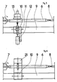
- the installation of FIG. 3 comprises a lathe on which the substrate 6 is held in axial compression between a mandrel 7 and a tailstock 8 and driven in rotation, while on the bench 9 of the lathe moves longitudinally a carriage 10 carrying a spray gun 11 and a coil 12 for winding a gun power cord.
- An extractor hood 13 moves at the same time as the carriage 10.
- These probes 14 extend longitudinally on the cores from the holes 15 or the locations which receive their active end, to reach one or the other of the two longitudinal ends of the axial succession of carrots.
- These probes 14 make it possible to determine the temperature difference between the inside of the cores and the external surface of the latter.
- tubular metal end pieces 16 made of stainless steel and discs made of sintered material 17 so that it is thus possible to form, after execution of a waterproof metallic coating on all the carrots , a conduit in which the discs 17 ensure good distribution of a fluid through the cores.
- This fluid can be constituted, for example, by air or oxygen injected at very high temperature and one can follow the front of the combustion thus generated. We can in this way reconstitute in the laboratory operating conditions similar to those existing at the depth from which the carrots were taken.
- a ceramic underlay 18 is deposited laterally on the axial succession of the cores by means of the installation of FIG. 3 in which the spray gun 11 is an oxy-acetylene flame gun fed by a flexible cord of the blue corundum type.
- the gun 11 is automatically moved in longitudinal translation while all the cores are rotated. A uniform sub-layer is thus obtained, the thickness of which is, for example, 0.3 mm.
- an intermediate layer 19 for example 0.7 mm thick, is deposited with the same installation and a flexible cord of nickel aluminide.
- This coating 20 is remelted by inductive heating using the installation of FIG. 4 which includes a tower such as that of FIG. 3, but the carriage 10 of which carries a high frequency generator 21.
- a thick ceramic coating 22 In the embodiment according to FIG. 2 to deposit on the metallic coating 20 a thick ceramic coating 22. To ensure the adhesion of this new deposit, the exterior surface of the metallic coating 20 has been etched with an abrasive jet, for example corundum. make this surface rough, the roughness being between 6 and 15 ⁇ Ra The adhesion was improved by depositing, by hot spraying, a bonding layer of nickel aluminide with 5% aluminum, with a thickness of 50 to 100 ⁇ m. ⁇ m. On this bonding layer, the thick ceramic coating 22, for example 10 mm thick, was sprayed hot, which serves as a thermal barrier. This coating thick 22 can in particular be obtained from a bead of blue alumina corundum with 3% titanium oxide.
- annular space 23 has been provided, formed for example between the covering 22 covered with a sealing layer 24 1 mm thick in a synthetic resin and an outer envelope 25 comprising an outer layer of coated KEVLAR fibers 26 4 mm thick and an inner layer of synthetic rubber 27 1 mm thick.
- the outer casing 25 is held at its longitudinal ends by conventional support means not shown here.
- the annular space 23 has, for example, a thickness of 2.5 mm and it is used for the circulation of a cooling fluid.
Description
L'invention concerne un procédé de fabrication d'un revêtement métallique adhérent réalisé sur un substrat minéral du type roche, tel que des grès ou des roches quelconques.The invention relates to a method of manufacturing an adherent metallic coating produced on a mineral substrate of the rock type, such as any sandstone or rock.
On sait que l'on peut effectuer des revêtements métalliques sur divers substrats par les techniques de projection à chaud d'un matériau d'apport constitué par un alliage métallique dit "autofusible" sous forme de particules fondues ou à l'état pâteux qui, par l'effet de la vitesse à laquelle elles sont soumises, viennent s'écraser sur le substrat en formant une couche plus ou moins poreuse et plus ou moins adhérente. Le matériau d'apport peut se présenter sous forme de fils pleins, de fils fourrés, de baguettes, de cordons souples, de poudres. La température à laquelle sont portées les particules peut être obtenue par des combustions de gaz ou des arcs électriques. La vitesse des particules, provoquée par l'action de gaz comprimés, de flammes de combustion ou de colonnes de plasmas, peut varier de quelques mètres par seconde à plusieurs fois la vitesse du son. On utilise pour cette projection à chaud des pistolets à flamme y compris des canons à détonation et des pistolets à arc électrique y compris des générateurs de plasmas.It is known that metallic coatings can be made on various substrates by the techniques of hot spraying of a filler material constituted by a metallic alloy known as "autofusible" in the form of molten particles or in a pasty state which, by the effect of the speed to which they are subjected, come crashing onto the substrate, forming a more or less porous and more or less adherent layer. The filler material may be in the form of solid wires, filled wires, rods, flexible cords, powders. The temperature to which the particles are brought can be obtained by gas combustions or electric arcs. The speed of particles, caused by the action of compressed gases, flames of combustion or columns of plasmas, can vary from a few meters per second to several times the speed of sound. For this hot spraying, flame pistols including detonation guns and electric arc pistols including plasma generators are used.
On sait que l'on peut densifier la couche déposée afin d'éliminer toutes les porosités et d'obtenir un dépôt métallique étanche en effectuant une fusion de cette couche, par chauffage, par exemple, à induction, à gaz, à laser et à faisceau d'électrons, d'un métal ou d'un alliage métallique.It is known that the deposited layer can be densified in order to eliminate all the porosities and to obtain a tight metallic deposit by effecting a fusion of this layer, by heating, for example, by induction, gas, laser and beam of electrons, a metal or a metal alloy.
Mais avec un substrat minéral du type roche, on se heurte à des difficultés d'adhérence du revêtement métallique telles que la réalisation d'un revêtement métallique étanche sur un tel substrat paraissait jusqu'ici impossible.However, with a mineral substrate of the rock type, it is encountered with adhesion difficulties of the metal coating such that the production of a sealed metal coating on such a substrate has hitherto seemed impossible.
La présente invention a pour objectif de rendre cette réalisation possible et elle prévoit à cette effet une couche intermédiaire qui permet, en outre, d'encaisser les contraintes dues à la fusion et au retrait de l'alliage métallique constituant le revêtement métallique et qui peut, si le substrat minéral du type roche est formé de plusieurs pièces, maintenir temporairement celles-ci en position pendant la projection et la refusion de cet alliage métallique et contribuer ensuite à leur maintien définitif.The present invention aims to make this possible realization and it provides for this purpose an intermediate layer which also makes it possible to absorb the stresses due to the melting and withdrawal of the metal alloy constituting the metal coating and which can, if the mineral substrate of the rock type is formed of several parts, temporarily hold them in position during projection and reflow this metallic alloy and then contribute to their final maintenance.
Un premier objet de l'invention est un procédé de fabrication d'un revêtement métallique sur un substrat minéral du type roche selon la revendication 1.A first object of the invention is a method of manufacturing a metallic coating on a mineral substrate of the rock type according to
Cette couche intermédiaire peut être elle-même déposée sur une sous-couche en une céramique prise dans la liste des oxydes d'aluminium et de zirconium et des hydrures de titane, formée par projection à chaud sur le substrat minéral. Cette sous-couche améliore encore l'adhérence de la couche intermédiaire sur certains substrats et elle contribue éventuellement au maintien des pièces formant le substrat.This intermediate layer can itself be deposited on a ceramic sublayer taken from the list of aluminum and zirconium oxides and titanium hydrides, formed by hot spraying on the mineral substrate. This sub-layer further improves the adhesion of the intermediate layer to certain substrates and it possibly contributes to the maintenance of the parts forming the substrate.
Par les brevets FR-A-1 505 106 et GB-A-1 162 390, on connaît un procédé de fabrication d'un composant électrique à corps céramique, qui consiste à déposer sur ledit corps une couche de chrome-nickel par vaporisation sous vide puis une couche de métal soudable sur la couche précédente également par vaporisation sous vide. Toutefois, la technique de la vaporisation sous vide est totalement différente de celle de la projection à chaud, et, de plus, par ce procédé, on n'arrivera pas à déposer un revêtement métallique sur une roche, telle que du grès.From patents FR-A-1 505 106 and GB-A-1 162 390, a process for manufacturing an electrical component with a ceramic body is known, which consists in depositing on said body a layer of chromium-nickel by vaporization under vacuum then a layer of weldable metal on the previous layer also by vacuum spraying. However, the technique of vacuum spraying is completely different from that of hot spraying, and, moreover, by this process, it will not be possible to deposit a metallic coating on a rock, such as sandstone.
Le brevet GB-A-1 133 403 concerne également un procédé de dépôt de couches métalliques sur un substrat en silice pure, à partir d'une source d'alumine chauffée par bombardement électronique sous une très faible pression. Il s'agit donc ici également d'une vaporisation sous vide. Par ce procédé, on ne pourra donc pas réaliser un dépôt métallique sur une roche.Patent GB-A-1,133,403 also relates to a process for depositing metallic layers on a pure silica substrate, from a source of alumina heated by electron bombardment under very low pressure. This is therefore also a vacuum spraying here. By this method, it will therefore not be possible to produce a metallic deposit on a rock.
On connaît également par JP-A-58 213 864 un procédé de revêtement par projection à chaud sur une paroi métallique, ce qui n'a donc rien à voir avec le revêtement d'une roche. De plus, les couches déposées ne sont pas refondues pour les rendre étanches. Enfin, la couche intermédiaire contient seulement du nickel-chrome mais pas d'aluminures de nickel et de titane.JP-A-58 213 864 also discloses a method of coating by hot spraying onto a metal wall, which therefore has nothing to do with coating a rock. In addition, the deposited layers are not remelted to make them waterproof. Finally, the intermediate layer contains only nickel-chromium but no nickel and titanium aluminides.
Les mêmes objections peuvent être formulées à l'encontre des brevets JP-A-57 89 470, 57 140 876 et DE-A-2 545 242 dans lesquels le substrat est métallique.The same objections can be made to against patents JP-A-57 89 470, 57 140 876 and DE-A-2 545 242 in which the substrate is metallic.
Selon l'invention, des sondes de mesure sont montées sur le substrat minéral et recouvertes par ladite couche intermédiaire qui les maintient en place. Ces sondes se trouvent noyées soit dans une portion de l'épaisseur de la couche intermédiaire soit dans ladite sous-couche si celle-ci existe.According to the invention, measurement probes are mounted on the mineral substrate and covered by said intermediate layer which holds them in place. These probes are embedded either in a portion of the thickness of the intermediate layer or in said sub-layer if it exists.
L'épaisseur de la sous-couche sera généralement inférieure à 0,5 mm et celle de la couche intermédiaire ainsi que dudit revêtement métallique sera généralement inférieure à 1 mm.The thickness of the sub-layer will generally be less than 0.5 mm and that of the intermediate layer and of said metallic coating will generally be less than 1 mm.
Ce revêtement métallique présente une surface extérieure rendue rugueuse et servant de support à un entourage poreux plus épais, et un matériau choisi dans la liste des matériaux métalliques et céramiques, déposé par projection à chaud. L'épaisseur de cet entourage sera généralement de plusieurs millimètres afin de pouvoir réaliser une isolation thermique et y faire circuler un fluide.This metallic coating has a roughened exterior surface serving as a support for a thicker porous surrounding, and a material chosen from the list of metallic and ceramic materials, deposited by hot spraying. The thickness of this surround will generally be several millimeters in order to be able to achieve thermal insulation and circulate a fluid therein.
L'invention a pour second objet un produit revêtu selon les revendications 4 à 8.A second object of the invention is a coated product according to claims 4 to 8.
D'autres particularités de l'invention ressortiront d'un exemple de réalisation qui va être décrit, à titre non limitatif, en se référant aux dessins joints dans lesquels :
La figure 1 est une coupe axiale d'une portion d'un substrat minéral du type roche sur lequel on a déposé une sous-couche, une couche intermédiaire et un revêtement métallique étanche ;
- la Fig. 2 est une coupe axiale d'une portion d'un substrat ayant reçu les mêmes dépôts et en plus un dépôt extérieur épais en céramique ;
- la Fig. 3 représente schématiquement, en élévation, une installation de projection de matériaux d'apport sur un substrat ; et
- la Fig. 4 représente schématiquement, en élévation, une installation de refusion du revêtement métallique.
FIG. 1 is an axial section of a portion of a mineral substrate of the rock type on which a sub-layer, an intermediate layer and a waterproof metallic coating have been deposited;
- Fig. 2 is an axial section of a portion of a substrate having received the same deposits and in addition a thick external ceramic deposit;
- Fig. 3 schematically represents, in elevation, an installation for projecting filler materials onto a substrate; and
- Fig. 4 schematically shows, in elevation, a reflow installation of the metal coating.
Dans cet exemple, le substrat est constitué par une succession axiale de carottes cylindriques prélevées dans une formation naturelle, par exemple trente carottes en grès d'un diamètre de 60 mm et d'une longueur de 100 mm placées bout à bout et maintenues pressées les unes contre les autres pour former dans leur ensemble un substrat de 3 mètres de long. On voit deux de ces carottes en 1 et 2 sur la Fig. 1 et trois autres carottes 3, 4, 5 sur la Fig. 2. L'installation de la Fig. 3 comporte un tour sur lequel le substrat 6 est tenu en compression axiale entre un mandrin 7 et une contre-pointe 8 et entraîné en rotation, tandis que sur le banc 9 du tour se déplace longitudinalement un chariot 10 porteur d'un pistolet de projection 11 et d'une bobine 12 d'enroulement d'un cordon d'alimentation du pistolet. Une hotte d'aspiration 13 se déplace en même temps que le chariot 10.In this example, the substrate consists of an axial succession of cylindrical cores taken from a natural formation, for example thirty sandstone cores with a diameter of 60 mm and a length of 100 mm placed end to end and kept pressed. against each other to form a
On voit sur les Fig. 1 et 2 des sondes de mesure 14, constituées ici par des thermocouples, dont l'extrémité active est introduite dans des trous 15 percés dans les carottes ou placée à la surface des carottes. Ces sondes 14 s'étendent longitudinalement sur les carottes à partir des trous 15 ou des emplacements qui reçoivent leur extrémité active, pour atteindre l'une ou l'autre des deux extrémités longitudinales de la succession axiale de carottes. Ces sondes 14 permettent de déterminer la différence de température entre l'intérieur des carottes et la surface extérieure de celles-ci.We see in Figs. 1 and 2 of the
Aux extrémités axiales de l'ensemble des carottes sont disposés des embouts métalliques tubulaires 16 en acier inoxydable et des disques en matériau fritté 17 de sorte que l'on peut ainsi constituer, après exécution d'un revêtement métallique étanche sur l'ensemble des carottes, un conduit dans lequel les disques 17 assurent une bonne répartition d'un fluide à travers les carottes. Ce fluide peut être constitué, par exemple, par de l'air ou de l'oxygène injecté à très haute température et on peut suivre le front de la combustion ainsi engendrée. On peut de cette manière reconstituer en laboratoire des conditions opératoires similaires à celles existant à la profondeur à laquelle les carottes ont été prélevées.At the axial ends of the set of carrots are arranged tubular
Une sous-couche en céramique 18 est déposée latéralement sur la succession axiale des carottes au moyen de l'installation de la Fig. 3 dans laquelle le pistolet de projection 11 est un pistolet à flamme oxy-acétylénique alimenté par un cordon souple du type corindon bleu. Le pistolet 11 est déplacé automatiquement en translation longitudinale tandis que l'ensemble des carottes est entraîné en rotation. On obtient ainsi une sous-couche uniforme dont l'épaisseur est, par exemple, de 0,3 mm.A
Sur cette sous-couche et sur une portion des embouts 16 on dépose avec la même installation et un cordon souple en aluminiure de nickel une couche intermédiaire 19, par exemple d'une épaisseur de 0,7 mm.On this sub-layer and on a portion of the
De même, sur cette couche intermédiaire 19 et une portion supplémentaire des embouts 16, on effectue, à l'aide de l'installation de la Fig. 3 dans laquelle le pistolet 11 est utilisé avec un cordon souple autofusible à base de nickel, un revêtement métallique 20 d'une épaisseur de 0,8 mm, par exemple.Likewise, on this
Ce revêtement 20 est refondu par chauffage inductif à l'aide de l'installation de la Fig. 4 qui comporte un tour tel que celui de la Fig. 3, mais dont le chariot 10 porte un générateur à haute fréquence 21.This
On obtient ainsi autour de la succession axiale de carottes un revêtement étanche lié de manière étanche aux embouts 16, retenant les carottes les unes contre les autres et les sondes de mesure contre les carottes et appliqué latéralement contre la succession axiale de carottes.There is thus obtained around the axial succession of carrots a tight coating tightly linked to the
On a prévu dans la réalisation selon la Fig. 2 de déposer sur le revêtement métallique 20 un revêtement épais en céramique 22. Pour assurer l'adhérence de ce nouveau dépôt, on a décapé au jet d'abrasif, par exemple du corindon, la surface extérieure du revêtement métallique 20, de manière à rendre cette surface rugueuse, la rugosité étant comprise entre 6 et 15 µRa. On a amélioré l'adhérence en déposant, par projection à chaud, une couche d'accrochage en aluminiure de nickel à 5 % d'aluminium, d'une épaisseur de 50 à 100 µm. µm. Sur cette couche d'accrochage on a projeté à chaud le revêtement épais en céramique 22, par exemple de 10 mm d'épaisseur, qui sert de barrière thermique. Ce revêtement épais 22 peut notamment être obtenu à partir d'un cordon de corindon bleu d'alumine à 3 % d'oxyde de titane.In the embodiment according to FIG. 2 to deposit on the metallic coating 20 a thick
Dans la réalisation selon la Fig. 2, on a prévu un espace annulaire 23 formé par exemple entre le revêtement 22 recouvert d'une couche d'étanchéité 24 de 1 mm d'épaisseur en une résine synthétique et une enveloppe extérieure 25 comprenant une couche extérieure de fibres de KEVLAR enrobées 26 de 4 mm d'épaisseur et une couche intérieure en caoutchouc synthétique 27 de 1 mm d'épaisseur. L'enveloppe extérieure 25 est tenue à ses extrémités longitudinales par des moyens de support classiques non représentés ici. L'espace annulaire 23 a, par exemple, une épaisseur de 2,5 mm et il est utilisé pour la circulation d'un fluide de refroidissement.In the embodiment according to FIG. 2, an
Claims (8)
- Method of manufacturing an adherent metal coating formed on a mineral substrate of rock type, characterized in that it consists :- in the hot projection on the substrate (6) of an intermediate porous layer (19) made from a refractory metal alloy chosen from the list of nickel-chromium alloys and nickel and titanium aluminides,- then in the hot projection of a metal alloy layer (20) on the intermediate layer,- and in re-melting the metal alloy layer (20) so as to make it impervious.
- Method according to claim 1, characterized in that the intermediate layer is itself deposited on a porous under-layer (18) made from a ceramic taken from the list of aluminium and zirconium oxides and titanium hydrides, said under-layer being formed by hot projection on the mineral substrate (6).
- Method according to one of claims 1 and 2, characterized in that the surface of the metal alloy layer (20) is roughened, and in that a thick ceramic coating (22) is deposited thereon.
- Coated product obtained by the method according to claim 1, characterized in that it comprises :- a mineral substrate of rock type (6),- a porous intermediate layer (198) made from a refractory metal alloy chosen from the list of nickel-chrome alloys and nickel and titanium aluminides and is deposited on the mineral substrate of rock type,- and an impervious and re-melted metal alloy layer (20) deposited on the intermediate layer.
- Coated product obtained by the method according to claim 2, characterized in that it comprises :- a mineral substrate of rock type (6),- an under-layer (18) made from a porous ceramic taken from the list of aluminium and zirconium oxides and titanium hydrides and deposited on the mineral substrate of rock type,- a porous intermediate layer (19) made from a refractory metal alloy of the nickel- chromium metal alloy and nickel and titanium aluminide type,- and an impervious and re-melted layer made from metal alloy (20).
- Coated product according to one of claims 4 and 5, characterized in that the impervious metal alloy layer (20) comprises an external roughened surface serving as a support for a thicker coating (22) made from a material chosen from the list of metal and ceramic materials.
- Coated product according to one of claims 4 to 6, characterized in that measurement probes (14), mounted on the mineral substrate of rock type (6), are coated and held in position by said intermediate layer (19).
- Coated product according to one of claims 4 to 7, characterized in that it comprises a mineral substrate of rock type (6) in the form of an elongate cylinder formed by an axial succession of cylindrical core samples taken from a natural rock formation and applied end to end against each other, two tubular metal end pieces (16) mounted at the axial ends of the succession of core samples and several layers (18, 19, 20) deposited successively on the free lateral walls of the core samples, the impervious metal alloy layer (20) also coating a portion of the tubular end pieces (16).
Applications Claiming Priority (2)
| Application Number | Priority Date | Filing Date | Title |
|---|---|---|---|
| FR8615319 | 1986-11-04 | ||
| FR8615319A FR2606037B1 (en) | 1986-11-04 | 1986-11-04 | METAL COATING MADE ON A MINERAL SUBSTRATE |
Publications (2)
| Publication Number | Publication Date |
|---|---|
| EP0269480A1 EP0269480A1 (en) | 1988-06-01 |
| EP0269480B1 true EP0269480B1 (en) | 1991-06-26 |
Family
ID=9340489
Family Applications (1)
| Application Number | Title | Priority Date | Filing Date |
|---|---|---|---|
| EP87402364A Expired - Lifetime EP0269480B1 (en) | 1986-11-04 | 1987-10-21 | Metallic coating on a mineral substrate |
Country Status (6)
| Country | Link |
|---|---|
| US (1) | US4839239A (en) |
| EP (1) | EP0269480B1 (en) |
| DE (1) | DE3771040D1 (en) |
| ES (1) | ES2022914B3 (en) |
| FR (1) | FR2606037B1 (en) |
| GB (1) | GB2198151B (en) |
Families Citing this family (16)
| Publication number | Priority date | Publication date | Assignee | Title |
|---|---|---|---|---|
| DE3907084A1 (en) * | 1989-03-04 | 1990-09-13 | Battelle Institut E V | REVERSIBLE STORAGE FOR MEDIA AND USE OF THE STORAGE |
| DE3910725C1 (en) * | 1989-04-03 | 1990-10-31 | Hydraudyne Cylinders B., Boxtel, Nl | |
| AU627583B2 (en) * | 1989-05-10 | 1992-08-27 | Alcan International Limited | Manufacture of poppet valves by spray deposition |
| US5201939A (en) * | 1989-12-04 | 1993-04-13 | General Electric Company | Method of modifying titanium aluminide composition |
| CA2041418A1 (en) * | 1990-05-31 | 1991-12-01 | Albert G. Tobin | Method of protecting ceramic surfaces |
| EP0480404B1 (en) * | 1990-10-09 | 1995-07-19 | Daido Tokushuko Kabushiki Kaisha | Corrosion-resistant and heat-resistant metal composite and method of producing |
| US5714243A (en) * | 1990-12-10 | 1998-02-03 | Xerox Corporation | Dielectric image receiving member |
| US5232522A (en) * | 1991-10-17 | 1993-08-03 | The Dow Chemical Company | Rapid omnidirectional compaction process for producing metal nitride, carbide, or carbonitride coating on ceramic substrate |
| JP2763840B2 (en) * | 1991-11-26 | 1998-06-11 | 大同ほくさん株式会社 | Insulated pipe body and its manufacturing method |
| FR2692314B1 (en) * | 1992-06-10 | 1994-09-23 | Total Sa | Consolidation and sealing process for a rock sample. |
| US5582874A (en) * | 1994-11-29 | 1996-12-10 | United Container Machinery Group, Inc. | Method for coating corrugating rolls using high velocity oxygen fueled thermal spray |
| FR2731425B1 (en) * | 1995-03-08 | 1997-05-30 | Europ Propulsion | METHOD FOR COATING A PART IN COMPOSITE REFRACTORY MATERIAL WITH A METALLIC ENCLOSURE, AND PRODUCTS OBTAINED |
| US5711826A (en) * | 1996-04-12 | 1998-01-27 | Crs Holdings, Inc. | Functionally gradient cladding for nuclear fuel rods |
| US6175485B1 (en) | 1996-07-19 | 2001-01-16 | Applied Materials, Inc. | Electrostatic chuck and method for fabricating the same |
| US7278353B2 (en) * | 2003-05-27 | 2007-10-09 | Surface Treatment Technologies, Inc. | Reactive shaped charges and thermal spray methods of making same |
| US9499895B2 (en) * | 2003-06-16 | 2016-11-22 | Surface Treatment Technologies, Inc. | Reactive materials and thermal spray methods of making same |
Family Cites Families (28)
| Publication number | Priority date | Publication date | Assignee | Title |
|---|---|---|---|---|
| FR773928A (en) * | 1934-12-29 | 1934-11-28 | Nat Standard Co | Improvements to steel articles coated with other bodies and methods of manufacturing such articles |
| FR1090257A (en) * | 1953-11-13 | 1955-03-29 | Libbey Owens Ford Glass Co | Ceramic or glass articles covered with a conductive coating |
| US3010480A (en) * | 1958-10-13 | 1961-11-28 | Clifford A Ragsdale | Thermocouple tube and protective coating |
| GB949612A (en) * | 1959-06-26 | 1964-02-12 | Eaton Mfg Co | A process for supplying a coating on at least a portion of a metallic surface and a metal article produced in such process |
| DE1144418B (en) * | 1961-07-20 | 1963-02-28 | Siemens Planiawerke A G Fuer K | Process for producing a contact layer on a silicon-containing material |
| FR1434158A (en) * | 1964-11-25 | 1966-04-08 | Sfec | Improvements to refractory protective coatings, and method of manufacturing these elements |
| NL6516296A (en) * | 1965-12-15 | 1967-06-16 | ||
| GB1133403A (en) * | 1967-03-31 | 1968-11-13 | Standard Telephones Cables Ltd | Deposition of metal layers on insulators |
| NO124145B (en) * | 1967-04-17 | 1972-03-06 | Mitsubishi Steel Manufacturing | |
| US3620808A (en) * | 1968-01-05 | 1971-11-16 | James E Monroe Jr | Method of forming a thermal emissivity coating on a metallic substrate |
| AT278983B (en) * | 1968-08-12 | 1970-02-25 | Plansee Metallwerk | Process for the production of rotating anodes for X-ray tubes |
| FR1600296A (en) * | 1968-12-31 | 1970-07-20 | ||
| FR2037986A5 (en) * | 1969-03-14 | 1970-12-31 | Leybold Heraeus Verwaltung | Vacuum deposition of layers of transparent - material onto glass |
| SE360347B (en) * | 1969-05-02 | 1973-09-24 | Beers Ltd De | |
| US3967017A (en) * | 1970-03-17 | 1976-06-29 | John Anthony Marten | Method of coating a vehicle test bed rollers |
| GB1393031A (en) * | 1972-06-06 | 1975-05-07 | Sperl R J | Metal plating product and process |
| FR2201542B1 (en) * | 1972-10-02 | 1977-09-09 | Bendix Corp | |
| US3814447A (en) * | 1972-11-02 | 1974-06-04 | Ramsey Corp | Sealing element for use in internal combustion engines |
| US3890069A (en) * | 1973-07-05 | 1975-06-17 | Ford Motor Co | Coating for rotary engine rotor housings and method of making |
| US3888746A (en) * | 1974-01-04 | 1975-06-10 | Ford Motor Co | Method of providing an intermediate steel layer for chrome plating on rotor housings |
| DE2545242A1 (en) * | 1975-10-09 | 1977-04-21 | Metallgesellschaft Ag | Pistons or cylinders with flame sprayed coating - of nickel aluminide followed by molybdenum, suitable for engines burning methanol |
| FR2334431A1 (en) * | 1975-12-12 | 1977-07-08 | Gen Electric | THERMAL SPRAYING DEPOSIT PROCESS |
| DE2720726C3 (en) * | 1977-05-07 | 1980-12-18 | Brown, Boveri & Cie Ag, 6800 Mannheim | Electrochemical alkali-sulfur storage cell or battery |
| DE3018620C2 (en) * | 1980-05-16 | 1982-08-26 | MTU Motoren- und Turbinen-Union München GmbH, 8000 München | Thermally insulating and sealing lining for a thermal turbo machine |
| JPS5789470A (en) * | 1980-11-22 | 1982-06-03 | Kawasaki Steel Corp | Formation of plasma spray-coated film on welded part |
| JPS57140876A (en) * | 1981-02-23 | 1982-08-31 | Toshiba Corp | Heat resistant ceramic coating |
| JPS58213864A (en) * | 1982-06-04 | 1983-12-12 | Nippon Steel Corp | Coating method of shell of hot stove |
| DE3315556C1 (en) * | 1983-04-29 | 1984-11-29 | Goetze Ag, 5093 Burscheid | Wear-resistant coating |
-
1986
- 1986-11-04 FR FR8615319A patent/FR2606037B1/en not_active Expired
-
1987
- 1987-10-21 ES ES87402364T patent/ES2022914B3/en not_active Expired - Lifetime
- 1987-10-21 EP EP87402364A patent/EP0269480B1/en not_active Expired - Lifetime
- 1987-10-21 DE DE8787402364T patent/DE3771040D1/en not_active Expired - Lifetime
- 1987-11-02 GB GB8725628A patent/GB2198151B/en not_active Expired - Lifetime
- 1987-11-04 US US07/116,300 patent/US4839239A/en not_active Expired - Fee Related
Also Published As
| Publication number | Publication date |
|---|---|
| GB8725628D0 (en) | 1987-12-09 |
| FR2606037B1 (en) | 1989-02-03 |
| FR2606037A1 (en) | 1988-05-06 |
| GB2198151A (en) | 1988-06-08 |
| US4839239A (en) | 1989-06-13 |
| EP0269480A1 (en) | 1988-06-01 |
| ES2022914B3 (en) | 1991-12-16 |
| GB2198151B (en) | 1991-05-29 |
| DE3771040D1 (en) | 1991-08-01 |
Similar Documents
| Publication | Publication Date | Title |
|---|---|---|
| EP0269480B1 (en) | Metallic coating on a mineral substrate | |
| US8857698B2 (en) | Method for manufacturing insulating glazing | |
| FR2587109A1 (en) | PROTECTIVE SHEATH AND DEVICE FOR A IMMERSION PYROMETER AND METHOD FOR PRODUCING THE SAME | |
| US7494723B2 (en) | Y2O3 spray-coated member and production method thereof | |
| CA1335439C (en) | Alloy heat engine parts covered with a metal-ceramic protective coating | |
| FR2518123A1 (en) | PROCESS FOR APPLYING A COATING OF CERAMIC MATERIAL ON A METALLIC SUBSTRATE AND ARTICLE OBTAINED | |
| FR2644088A1 (en) | METHOD FOR MANUFACTURING FOUNDRY ELBOW | |
| FR2459879A1 (en) | AIR-COOLED SEAL WITH CERAMIC MATERIAL FOR A GAS TURBINE ENGINE | |
| FR2969521A1 (en) | METHOD FOR FORMING PASSAGE HOLES IN A HIGH TEMPERATURE SUBSTRATE | |
| EP0661720B1 (en) | Use of a method for coating by semi-transfered arc for the protection of a heterogenous zone of a nuclear component and a coating device | |
| EP0628235B1 (en) | Method for making a sealed passage in a refractory composite part, and application to the production of a refractory composite structure cooled by fluid circulation | |
| EP0421865B1 (en) | Rocket combustion chamber | |
| FR2827308A1 (en) | PROCESS FOR GLOBAL REPAIR OF A PART COATED WITH A THERMAL BARRIER | |
| EP3071722B1 (en) | Integrated sintering process for microcracking and erosion resistance of thermal barriers | |
| US7144602B2 (en) | Process for obtaining a flexible/adaptive thermal barrier | |
| ITRM970437A1 (en) | PROCEDURE FOR THE PRODUCTION OF THICK COATINGS ON COMPONENTS IN COPPER OR ITS ALLOYS | |
| BE1000078A6 (en) | Internal plasma spray coating of tube - esp. steam generator tube to inhibit stress corrosion cracking | |
| JP2001323361A (en) | Radiant tube excellent in high temperature oxidation resistance and its production method | |
| Kiełczawa et al. | Isothermal oxidation behavior of MCrAlY bond coats after laser microtexturing | |
| EP0757114A1 (en) | Quasicrystallic coating and process for coating | |
| EP1471162A1 (en) | Process for obtaining a flexo-adaptive thermal barrier coating | |
| US20210277510A1 (en) | Method for applying a thermal barrier | |
| EP0272527A2 (en) | Method for applying a metal coating to a substrate, and product obtained | |
| EP1645654A1 (en) | Method of manufacturing a flexible thermal barrier coating | |
| Gerdeman et al. | Plasma Spraying |
Legal Events
| Date | Code | Title | Description |
|---|---|---|---|
| PUAI | Public reference made under article 153(3) epc to a published international application that has entered the european phase |
Free format text: ORIGINAL CODE: 0009012 |
|
| AK | Designated contracting states |
Kind code of ref document: A1 Designated state(s): DE ES IT SE |
|
| 17P | Request for examination filed |
Effective date: 19880729 |
|
| 17Q | First examination report despatched |
Effective date: 19890717 |
|
| GRAA | (expected) grant |
Free format text: ORIGINAL CODE: 0009210 |
|
| AK | Designated contracting states |
Kind code of ref document: B1 Designated state(s): DE ES IT SE |
|
| ITF | It: translation for a ep patent filed |
Owner name: BARZANO' E ZANARDO MILANO S.P.A. |
|
| REF | Corresponds to: |
Ref document number: 3771040 Country of ref document: DE Date of ref document: 19910801 |
|
| PLBE | No opposition filed within time limit |
Free format text: ORIGINAL CODE: 0009261 |
|
| STAA | Information on the status of an ep patent application or granted ep patent |
Free format text: STATUS: NO OPPOSITION FILED WITHIN TIME LIMIT |
|
| 26N | No opposition filed | ||
| PGFP | Annual fee paid to national office [announced via postgrant information from national office to epo] |
Ref country code: SE Payment date: 19920921 Year of fee payment: 6 |
|
| PGFP | Annual fee paid to national office [announced via postgrant information from national office to epo] |
Ref country code: ES Payment date: 19921002 Year of fee payment: 6 |
|
| PGFP | Annual fee paid to national office [announced via postgrant information from national office to epo] |
Ref country code: DE Payment date: 19921229 Year of fee payment: 6 |
|
| PG25 | Lapsed in a contracting state [announced via postgrant information from national office to epo] |
Ref country code: SE Effective date: 19931022 Ref country code: ES Free format text: LAPSE BECAUSE OF EXPIRATION OF PROTECTION Effective date: 19931022 |
|
| PG25 | Lapsed in a contracting state [announced via postgrant information from national office to epo] |
Ref country code: DE Effective date: 19940701 |
|
| EUG | Se: european patent has lapsed |
Ref document number: 87402364.1 Effective date: 19940510 |
|
| REG | Reference to a national code |
Ref country code: ES Ref legal event code: FD2A Effective date: 19990601 |
|
| PG25 | Lapsed in a contracting state [announced via postgrant information from national office to epo] |
Ref country code: IT Free format text: LAPSE BECAUSE OF NON-PAYMENT OF DUE FEES;WARNING: LAPSES OF ITALIAN PATENTS WITH EFFECTIVE DATE BEFORE 2007 MAY HAVE OCCURRED AT ANY TIME BEFORE 2007. THE CORRECT EFFECTIVE DATE MAY BE DIFFERENT FROM THE ONE RECORDED. Effective date: 20051021 |