EP0268917B1 - Packaging machine, especially for cigarette packets - Google Patents
Packaging machine, especially for cigarette packets Download PDFInfo
- Publication number
- EP0268917B1 EP0268917B1 EP87116540A EP87116540A EP0268917B1 EP 0268917 B1 EP0268917 B1 EP 0268917B1 EP 87116540 A EP87116540 A EP 87116540A EP 87116540 A EP87116540 A EP 87116540A EP 0268917 B1 EP0268917 B1 EP 0268917B1
- Authority
- EP
- European Patent Office
- Prior art keywords
- folding
- turret
- turrets
- packaging machine
- production
- Prior art date
- Legal status (The legal status is an assumption and is not a legal conclusion. Google has not performed a legal analysis and makes no representation as to the accuracy of the status listed.)
- Expired - Lifetime
Links
Images

Classifications
-
- B—PERFORMING OPERATIONS; TRANSPORTING
- B65—CONVEYING; PACKING; STORING; HANDLING THIN OR FILAMENTARY MATERIAL
- B65B—MACHINES, APPARATUS OR DEVICES FOR, OR METHODS OF, PACKAGING ARTICLES OR MATERIALS; UNPACKING
- B65B19/00—Packaging rod-shaped or tubular articles susceptible to damage by abrasion or pressure, e.g. cigarettes, cigars, macaroni, spaghetti, drinking straws or welding electrodes
- B65B19/02—Packaging cigarettes
- B65B19/22—Wrapping the cigarettes; Packaging the cigarettes in containers formed by folding wrapping material around formers
- B65B19/223—Wrapping the cigarettes; Packaging the cigarettes in containers formed by folding wrapping material around formers in a curved path; in a combination of straight and curved paths, e.g. on rotary tables or other endless conveyors
-
- B—PERFORMING OPERATIONS; TRANSPORTING
- B65—CONVEYING; PACKING; STORING; HANDLING THIN OR FILAMENTARY MATERIAL
- B65B—MACHINES, APPARATUS OR DEVICES FOR, OR METHODS OF, PACKAGING ARTICLES OR MATERIALS; UNPACKING
- B65B65/00—Details peculiar to packaging machines and not otherwise provided for; Arrangements of such details
- B65B65/003—Packaging lines, e.g. general layout
- B65B65/006—Multiple parallel packaging lines
Definitions
- the invention relates to a packaging machine for the simultaneous production of several cigarette packs with two parallel, each having folding turrets production lines.
- the invention relates to a conventionally designed packaging machine with respect to individual organs, in particular for the production of cigarette packs.
- These can be designed as soft cup packs or as a hinged box (hinge-lid pack).
- a packaging machine for the production of such cigarette packs usually consists of at least one folding turret for the inside wrapping of Cigarette groups (tinfoil) and another folding turret for wrapping in a paper or cardboard blank.
- the packaging machine can be equipped with a dry turret and with conveying elements for feeding the packaging material and for transporting the (partial) packs.
- Packaging machines in double-track design are known. These are equipped with revolvers, conveyors etc., which are designed to hold two adjacent packs. The performance of such a double-lane packaging machine is considerably higher than that of a "simple" packaging machine. However, the double-track version is necessarily more prone to failure.
- US-A-2 810 998 shows double lane operation of a cigarette packaging machine.
- Two folding revolvers are provided, which are driven simultaneously via a stepping wheel and each take up packaging of one web. Both revolvers are on the same plane.
- US-A-3 293 825 also shows a two-lane operation. It is a packaging machine of a special type with superimposed lanes. Folding turrets are not provided.
- the invention has for its object to increase the performance of packaging machines for the production of cigarette packs and to reduce the effects of any malfunctions on the overall performance.
- each folding turret for the folding of blanks and conveyors for cigarette groups, packaging material and cigarette packs having production lines are provided, the folding turret and conveyor and possibly other units on opposite sides of a common one central support frame (housing) are arranged, and wherein the folding revolvers are independently driven independently and coaxially on both sides of the support frame are each mounted on one side.
- the packaging machine according to the invention is therefore of two lanes.
- the two production lines are separated from each other mechanically and functionally, but are nevertheless part of a uniform packaging machine.
- a complete set of the necessary folding, conveying and other organs is assigned to each production line. These are spaced from one another, namely on opposite sides of a common central support frame.
- the units and organs of the two production lines are driven independently of one another.
- a (current) reduction in performance in the area of one production line thus has no effect on the operation and thus on the performance in the area of the other production line.
- the folding units, conveyors, etc. of the two production lines are each assigned a separate, independent drive.
- a common drive can be assigned to both production lines, the aggregates and conveyors of the two production lines being able to be uncoupled individually from the common drive.
- the folding revolvers are coaxial on both sides of the support frame and are each mounted on one side.
- the supporting frame on the long sides of which the folding units (folding turret, conveyor, etc.) are mounted, is preferably at the same time a housing for receiving the drives for the folding members, conveyors, etc. of the two production lines.
- the packaging machine shown schematically in the drawings is designed for the production of cigarette packs 10 of the soft cup type.
- folding units, conveying units, etc. are formed for two complete production lines 12 and 13, respectively.
- Each of these production lines 12, 13 produces cigarette packs 10 independently of the other production line.
- each production line 12, 13, that is to say on both sides of the housing 11, are each complete for the packaging process.
- a receiving turret 14, a stannofold turret 15, a paper folding turret 16 and a drying turret 17 are mounted on the two longitudinal sides of the housing 11, namely on side walls 18 and 19 of the same, in the conveying direction.
- the aforementioned turrets 14, 17 of the two production lines 12 and 13 are each mounted coaxially, namely in bearing bushes 20, 21 of the housing 11.
- the turrets 14, 17 are aligned with one another in the vertical plane, in such a way that cigarette groups 22 and . (Partial) packs can be transferred from one revolver to another.
- the turrets 14, 17 can be driven continuously or, as in the exemplary embodiment shown, in cycles.
- each production line 12, 13 is assigned a separate cigarette magazine 23, 24.
- Cigarette groups 22 are removed from each of these conventional cigarette magazines 23, 24 by a double slide 25, 26 which can be moved back and forth transversely to the conveying direction.
- This fork-shaped double slide 25, 26 conveys two cigarette groups 22 into a cigarette conveyor 27, 28 per work cycle, which is designed here as a pocket chain with pockets 29 open on the sides and at the top for receiving a cigarette group 22.
- the endless cigarette conveyor 27, 28 ends adjacent to the first revolver, namely the receiving turret 14. This lies in a plane offset from the cigarette conveyor 27, 28, so that the cigarette groups 22 out of the pockets 29 of the cigarette conveyor 27, 28 are moved by means of transversely movable pushers 30, 31 can be transferred to a pocket 32 of the turret 14.
- the receiving turret 14 conveys the cigarette groups along a circular path of 180 ° to the immediate vicinity of the next turret, the Stanniolfaltrevolver 15.
- a tinfoil blank 33 is kept in a vertical, transverse position.
- the tinfoil blank 33 lies in a U-shaped manner around the group of cigarettes 22 in the known manner.
- the tinfoil blank 33 is fully folded.
- Cigarette groups 22 - tinfoil blocks - encased in the tinfoil blank 33 are pushed out of the pocket of the tinfoil folding turret 15 lying immediately adjacent to the paper folding turret 16 and inserted into a pocket of the paper folding turret 16.
- a further blank, namely a paper blank 34 is in turn U-shaped around the tinfoil block.
- the paper blank 34 is completely folded, namely with the formation of a soft cup.
- the paper folding turret 16 - except for the outer Foil wrapping - finished cigarette packs 10 ejected and thereby inserted into a pocket of the drying turret 17 arranged adjacent. This ensures curing or fastening of glue connections of the folding tabs which have been attached in the area of the paper folding turret 16. Furthermore, the shape of the pack in the area of the drying turret 17 is stabilized in a known manner.
- the cigarette packs 10 remain in the drying turret 17 during a three-quarter revolution of the latter.
- the packs are accordingly pushed out of the drying turret on the upper side in the axial direction onto a discharge path 35, 36.
- the two discharge paths 35, 36 lead to a transverse collecting path 37 in which the cigarettes with the small end faces are transported away pointing in the direction of conveyance.
- the collecting path 37 can lead to a film wrapping machine.
- the folding and conveying members of the two production lines 12, 13 are not arranged symmetrically to the central plane of the device, but offset in parallel. This makes it possible to arrange the cigarettes or cigarette groups 22 and the packs 10 of both production lines 12, 13 in the same direction.
- filter cigarettes are packaged.
- the filters of the cigarettes of both production lines 12, 13 are directed to the same side. This means a corresponding relative arrangement of the organs.
- the cigarette conveyor 27 of the (in FIG. 2) upper production line 12 is arranged in a plane between the turrets 14, 17 and the housing 11. The same applies to the position of the discharge conveyor 35.
- the two pushers 30, 31 are aligned in their pushing movements as a result of this relative position.
- the folding members of the folding revolvers 15, 16 are also arranged such that they correspond to the relative relative position of the cigarettes and packs 10.
- the turrets 14, 17 are rotatably supported by drive shafts 38, 39 in the associated bearing bushes 20, 21.
- an individual drive is provided for each production line 12, 13. It is a stepping gear 40, 41 (manifold).
- a driver 43 is rotatably driven about a vertical axis and engages with a shift star 44. This in turn is mounted on a shaft journal 45 of a main gear 46. With this, the drive shaft 38, 39 for the paper folding turret 16 is connected, so that the drive of the indexing gear 40, 41 is transmitted directly to this paper folding turret 16.
- Further drive gear wheels 47, 48 are mounted within the housing 11 for each production line 12, 13 or for the associated revolvers 14, 15, 17, specifically corresponding to the main gear wheel 46.
- the drive gear wheels 47, 48 are in engagement with the main gear wheel 46, so that its rotational movement is transmitted to the drive gears 47, 48 and ultimately to the turrets 14, 15 and 17.
- the drive shafts 38, 39 which are arranged coaxially, are rotatably mounted with pin ends 49 approximately in the middle of the housing 11 in a fixed support bushing 50.
- the transmission shafts 42 of the two stepping transmissions 40, 41 can be driven by separate drive motors.
- a solution is also conceivable in which a common drive motor is connected to the stepping transmissions 40, 41 via clutches.
- a solution comes into consideration in which a common step transmission is assigned to the two production lines 12, 13, of which the organs of the two Production lines 12, 13 can be uncoupled.
- an upright partition 51 is arranged in the center of the housing 11 in the exemplary embodiment shown.
- the packaging machine Due to the described design of the packaging machine, it has a higher performance than conventional two-lane packaging machines. In the event of intermittent business interruptions, disruptions etc. in the area of one production line, the other can continue to work without restrictions.
Description
Die Erfindung betrifft eine Verpackungsmaschine für die gleichzeitige Herstellung mehrerer Zigarettenpackungen mit zwei parallelen, jeweils Faltrevolver aufweisenden Fertigungsbahnen.The invention relates to a packaging machine for the simultaneous production of several cigarette packs with two parallel, each having folding turrets production lines.
Die Erfindung bezieht sich auf eine in bezug auf einzelne Organe standardmäßig, konventionell ausgebildete Verpackungsmaschine, im besonderen für die Herstellung von Zigarettenpackungen. Diese können als Weichbecher-Packungen oder als Klappschachtel (Hinge-Lid-Packung) ausgebildet sein. Eine Verpackungsmaschine für die Herstellung derartiger Zigarettenpackungen besteht üblicherweise mindestens aus einem Faltrevolver für den Inneneinschlag von Zigarettengruppen (Stanniol) und einem weiteren Faltrevolver für die Einhüllung in einen Papier- bzw. Kartonzuschnitt. Des weiteren kann die Verpackungsmaschine mit einem Trockenrevolver ausgestattet sein sowie mit Förderorganen für die Zuführung des Verpackungsmaterials und für den Transport der (Teil-)Packungen.The invention relates to a conventionally designed packaging machine with respect to individual organs, in particular for the production of cigarette packs. These can be designed as soft cup packs or as a hinged box (hinge-lid pack). A packaging machine for the production of such cigarette packs usually consists of at least one folding turret for the inside wrapping of Cigarette groups (tinfoil) and another folding turret for wrapping in a paper or cardboard blank. Furthermore, the packaging machine can be equipped with a dry turret and with conveying elements for feeding the packaging material and for transporting the (partial) packs.
Bekannt sind Verpackungsmaschinen in doppelbahniger Ausführung. Diese sind mit Revolvern, Förderern etc. ausgerüstet, die für die Aufnahme von jeweils zwei nebeneinanderliegenden Packungen bestimmt sind. Die Leistung einer derartigen doppelbahnigen Verpackungsmaschine ist beträchtlich höher als die einer "einfachen" Verpackungsmaschine. Allerdings ist die doppelbahnige Ausführung notwendigerweise störanfälliger.Packaging machines in double-track design are known. These are equipped with revolvers, conveyors etc., which are designed to hold two adjacent packs. The performance of such a double-lane packaging machine is considerably higher than that of a "simple" packaging machine. However, the double-track version is necessarily more prone to failure.
Die US-A-2 810 998 zeigt einen doppelbahnigen Betrieb einer Zigarettenverpackungsmaschine. Es sind zwei Faltrevolver vorgesehen, die über ein Schrittschaltrad simultan angetrieben werden und jeweils Verpackungen einer Bahn aufnehmen. Beide Revolver liegen in einer gemeinsamen Ebene.US-A-2 810 998 shows double lane operation of a cigarette packaging machine. Two folding revolvers are provided, which are driven simultaneously via a stepping wheel and each take up packaging of one web. Both revolvers are on the same plane.
Einen zweibahnigen Betrieb zeigt auch die US-A-3 293 825. Es handelt sich dabei um eine Verpackungsmaschine eines besonderen Typs mit übereinanderliegenden Bahnen. Faltrevolver sind nicht vorgesehen.US-A-3 293 825 also shows a two-lane operation. It is a packaging machine of a special type with superimposed lanes. Folding turrets are not provided.
Der Erfindung liegt die Aufgabe zugrunde, die Leistungsfähigkeit von Verpackungsmaschinen zur Herstellung von Zigarettenpackungen zu erhöhen und die Auswirkungen von etwaigen Störungen auf die Gesamtleistung zu mindern.The invention has for its object to increase the performance of packaging machines for the production of cigarette packs and to reduce the effects of any malfunctions on the overall performance.
Zur Lösung dieser Aufgabe sind zwei parallele, jeweils Faltrevolver für die Faltung von Zuschnitten und Förderer für Zigarettengruppen, Verpackungsmaterial und Zigarettenpackungen aufweisende Fertigungsbahnen vorgesehen, wobei die Faltrevolver und Förderer sowie gegebenenfalls weitere Aggregate an gegenüberliegenden Seiten eines gemeinsamen mittigen Traggestells (Gehäuse) angeordnet sind, und wobei die Faltrevolver voneinander unabhängig einzeln antreibbar und gleichachsig an beiden Seiten des Traggestells jeweils einseitig gelagert sind.To solve this problem, two parallel, each folding turret for the folding of blanks and conveyors for cigarette groups, packaging material and cigarette packs having production lines are provided, the folding turret and conveyor and possibly other units on opposite sides of a common one central support frame (housing) are arranged, and wherein the folding revolvers are independently driven independently and coaxially on both sides of the support frame are each mounted on one side.
Die erfindungsgemäße Verpackungsmaschine ist demnach zweibahnig ausgebildet. Die beiden Fertigungsbahnen sind jedoch maschinell und funktionell voneinander getrennt, gleichwohl aber Bestandteil einer einheitlichen Verpackungsmaschine. Jeder Fertigungsbahn ist ein kompletter Satz der erforderlichen Falt-, Förder- und sonstigen Organe zugeordnet. Diese sind mit Abstand voneinander, nämlich an gegenüberliegenden Seiten eines gemeinsamen mittigen Traggestells angeordnet.The packaging machine according to the invention is therefore of two lanes. However, the two production lines are separated from each other mechanically and functionally, but are nevertheless part of a uniform packaging machine. A complete set of the necessary folding, conveying and other organs is assigned to each production line. These are spaced from one another, namely on opposite sides of a common central support frame.
Die Aggregate und Organe der beiden Fertigungsbahnen werden erfindungsgemäß unabhängig voneinander angetrieben. Eine (momentane) Leistungsminderung im Bereich der einen Fertigungsbahn hat somit keine Auswirkungen auf den Betrieb und damit auf die Leistung im Bereich der anderen Fertigungsbahn. Zu diesem Zweck ist gemäß einem Ausführungsbeispiel den Faltaggregaten, Förderern etc. der beiden Fertigungsbahnen je ein gesonderter, selbständiger Antrieb zugeordnet. Alternativ kann beiden Fertigungsbahnen ein gemeinsamer Antrieb zugeordnet sein, wobei die Aggregate und Förderer der beiden Fertigungsbahnen individuell von dem gemeinsamen Antrieb abkuppelbar sind.According to the invention, the units and organs of the two production lines are driven independently of one another. A (current) reduction in performance in the area of one production line thus has no effect on the operation and thus on the performance in the area of the other production line. For this purpose, according to one exemplary embodiment, the folding units, conveyors, etc. of the two production lines are each assigned a separate, independent drive. Alternatively, a common drive can be assigned to both production lines, the aggregates and conveyors of the two production lines being able to be uncoupled individually from the common drive.
Zur Erfindung gehört weiterhin, daß die Faltrevolver an beiden Seiten des Traggestells gleichachsig und jeweils einseitig gelagert sind.It is also part of the invention that the folding revolvers are coaxial on both sides of the support frame and are each mounted on one side.
Das Traggestell, an dessen Längsseiten die Faltaggregate (Faltrevolver, Förderer etc.) gelagert sind, ist vorzugsweise zugleich ein Gehäuse zur Aufnahme der Antriebe für die Faltorgane, Förderer etc. der beiden Fertigungsbahnen.The supporting frame, on the long sides of which the folding units (folding turret, conveyor, etc.) are mounted, is preferably at the same time a housing for receiving the drives for the folding members, conveyors, etc. of the two production lines.
Ein Ausführungsbeispiel der Erfindung wird nachfolgend anhand der Zeichnungen näher erläutert. Es zeigt:
- Fig. 1
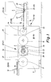
- eine Verpackungsmaschine für Zigaretten in vereinfachter Seitenansicht,
- Fig. 2
- die Verpackungsmaschine gemäß Fig. 1 im Grundriß, teilweise im Horizontalschnitt.
- Fig. 1
- a packaging machine for cigarettes in a simplified side view,
- Fig. 2
- 1 in plan, partly in horizontal section.
Die in den Zeichungen schematisch dargestellte Verpakkungsmaschine ist auf die Fertigung von Zigarettenpakkungen 10 des Typs Weichbecher ausgerichtet. Zu beiden Seiten eines annähernd mittigen Traggestells, nämlich eines kastenförmigen Gehäuses 11, sind Faltaggregate, Förderaggregate etc. für jeweis zwei komplette Fertigungsbahnen 12 und 13 gebildet. Jede dieser Fertigungsbahnen 12, 13 stellt Zigarettenpackungen 10 unabhängig von der anderen Fertigungsbahn her.The packaging machine shown schematically in the drawings is designed for the production of
Die im Bereich jeder Fertigungsbahn 12, 13, also zu beiden Seiten des Gehäuses 11 angeordneten Aggregate sind jeweils komplett für den Verpackungsvorgang. Bei dem gezeigten Beispiel sind in Förderrichtung aufeinanderfolgend ein Aufnahmerevolver 14, ein Stanniolfaltrevolver 15, ein Papierfaltrevolver 16 und ein Trockenrevolver 17 an den beiden Längseiten des Gehäuses 11, nämlich an Seitenwänden 18 und 19 desselben gelagert. Die vorgenannten Revolver 14..17 der beiden Fertigungsbahnen 12 und 13 sind jeweils gleichachsig gelagert, und zwar in Lagerbuchsen 20, 21 des Gehäuses 11. Des weiteren sind die Revolver 14..17 in vertikaler Ebene aufeinander ausgerichtet, derart, daß Zigarettengruppen 22 bzw. (Teil-)Packungen von einem Revolver zum anderen überführbar sind. Die Revolver 14..17 können je nach der Ausgestaltung der Verpackungsmaschine kontinuierlich oder - wie bei dem gezeigten Ausführungsbeispiel - taktweise angetrieben sein.The units arranged in the area of each
Jeder Fertigungsbahn 12, 13 ist bei dem vorliegenden Ausführungsbeispiel ein gesondertes Zigarettenmagazin 23, 24 zugeordnet. Jedem dieser im Aufbau konventionellen Zigarettenmagazine 23, 24 werden Zigarettengruppen 22 durch einen quer zur Förderrichtung hin- und herbewegbaren Doppelschieber 25, 26 entnommen. Dieser gabelförmig ausgebildete Doppelschieber 25, 26 fördert je Arbeitstakt zwei Zigarettengruppen 22 in einen Zigarettenförderer 27, 28, der hier als Taschenkette ausgebildet ist mit an den Seiten und oben offenen Taschen 29 zur Aufnahme einer Zigarettengruppe 22.In the present exemplary embodiment, each
Der endlose Zigarettenförderer 27, 28 endet benachbart zum ersten Revolver, nämlich dem Aufnahmerevolver 14. Dieser liegt in einer zum Zigarettenförder 27, 28 versetzten Ebene, so daß durch quer bewegbare Ausschieber 30, 31 die Zigarettengruppen 22 aus den Taschen 29 des Zigarettenförderers 27, 28 an eine Tasche 32 des Aufnahmerevolvers 14 übergeben werden können.The
Durch den Aufnahmerevolver 14 werden die Zigarettengruppen längs einer Kreisbahn von 180° gefördert bis zur unmittelbaren Nachbarschaft zum nächstfolgenden Revolver, dem Stanniolfaltrevolver 15.The receiving
In der Ebene zwischen dem Aufnahmerevolver 14 und dem Stanniolfaltrevolver 15 wird eine Stanniolzuschnitt 33 in vertikaler, quergerichteter Position bereitgehalten. Wenn eine Zigarettengruppe 22 aus dem Aufnahmerevolver 14 aus- und in eine Tasche des Stanniolfaltrevolvers 15 eingeschoben wird, legt sich der Stanniolzuschnitt 33 in der bekannten Weise U-förmig um die Zigarettengruppe 22 herum.In the plane between the receiving
Während der (taktweisen) Drehbewegung des Stanniolfaltrevolvers 15 längs einer Förderbahn von 180° wird der Stanniolzuschnitt 33 fertig gefaltet. In den Stanniolzuschnitt 33 eingehüllte Zigarettengruppen 22 - Stanniolblöcke - werden aus der jeweils unmittelbar benachbart zum Papierfaltrevolver 16 liegenden Tasche des Stanniolfaltrevolvers 15 aus und in eine Tasche des Papierfaltrevolvers 16 eingeschoben. Dabei legt sich ein weiterer Zuschnitt, nämlich ein Papierzuschnitt 34 wiederum U-förmig um den Stanniolblock herum. Während der Förderung durch den Papierfaltrevolver 16 wird der Papierzuschnitt 34 fertig gefaltet, nämlich unter Bildung eines Weichbechers.During the (intermittent) rotary movement of the
Aus dem Papierfaltrevolver 16 werden - bis auf die äußere Folienumhüllung - fertige Zigarettenpackungen 10 ausgestoßen und dabei in eine Tasche des benachbart angeordneten Trockenrevolvers 17 eingeführt. Dieser sorgt für eine Aushärtung bzw. Befestigung von Leimverbindungen der Faltlappen, die im Bereich des Papierfaltrevolvers 16 angebracht worden sind. Des weiteren wird die Form der Packung im Bereich des Trockenrevolvers 17 in bekannter Weise stabilisiert. Die Zigarettenpackungen 10 bleiben während einer Dreiviertel-Umdrehung des Trockenrevolvers 17 in diesem. Die Packungen werden demnach an der Oberseite in Axialrichtung aus dem Trockenrevolver ausgeschoben auf eine Abförderbahn 35, 36. Die beiden Abförderbahnen 35, 36 führen zu einer querlaufenden Sammelbahn 37, in der die Zigaretten mit den kleinen Stirnseiten in Förderrichtung weisend abtransportiert werden. Die Sammelbahn 37 kann zu einer Folieneinschlagmaschine führen.The paper folding turret 16 - except for the outer Foil wrapping - finished
Die Falt- und Förderorgane der beiden Fertigungsbahnen 12, 13 sind nicht symmetrisch zur Mittelebene der Vorrichtung angeordnet, sondern parallel versetzt. Dadurch ist es möglich, die Zigaretten bzw. Zigarettengruppen 22 und die Packungen 10 beider Fertigungsbahnen 12, 13 gleichgerichtet anzuordnen. Im vorliegenden Falle werden Filterzigaretten verpackt. Wie dargestellt, sind die Filter der Zigaretten beider Fertigungsbahnen 12, 13 zur selben Seite gerichtet. Dies bedeutet eine entsprechende Relativanordnung der Organe. So ist der Zigarettenförderer 27 der (in Fig. 2) oberen Fertigungsbahn 12 in einer Ebene zwischen den Revolvern 14..17 und dem Gehäuse 11 angeordnet. Gleiches gilt für die Position der Abförderbahn 35. Die beiden Ausschieber 30, 31 sind infolge dieser Relativstellung in ihren Ausschubbewegungen gleichgerichtet. Auch die Faltorgane der Faltrevolver 15, 16 sind so angeordnet, daß sie der gleichgerichteten Relativstellung der Zigaretten und Packungen 10 entsprechen.The folding and conveying members of the two
Die Revolver 14..17 sind drehbar mit Antriebswellen 38, 39 in den zugeordneten Lagerbuchsen 20, 21 gelagert. Bei diesem Ausführungsbeispiel ist ein individueller Antrieb für jede Fertigungsbahn 12, 13 vorgesehen. Es handelt sich dabei um ein Schrittschaltgetriebe 40, 41 (Manifold). Auf einer aufrechten Getriebewelle 42 ist jeweils ein um eine vertikale Achse drehend angetriebener Treiber 43 gelagert, der mit einem Schaltstern 44 in Eingriff steht. Dieser wiederum ist auf einem Wellenzapfen 45 eines Hauptzahnrades 46 angebracht. Mit diesem ist auch die Antriebswelle 38, 39 für den Papierfaltrevolver 16 verbunden, so daß der Antrieb des Schrittschaltgetriebes 40, 41 unmittelbar auf diesen Papierfaltrevolver 16 übertragen wird.The
Innerhalb des Gehäuses 11 sind für jede Fertigungsbahn 12, 13 bzw. für die zugeordneten Revolver 14, 15, 17 weitere Antriebszahnräder 47, 48 gelagert, und zwar entsprechend dem Hauptzahnrad 46. Die Antriebszahnräder 47, 48 stehen mit dem Hauptzahnrad 46 in Eingriff, so daß dessen Drehbewegung auf die Antriebszahnräder 47, 48 und letztlich auf die Revolver 14, 15 und 17 übertragen wird.Further
Zur statisch einwandfreien Lagerung sind die gleichachsig angeordneten Antriebswellen 38, 39 mit Zapfenden 49 etwa in der Mitte des Gehäuses 11 in einer fest angeordneten Stützbuchse 50 drehbar gelagert.For statically correct storage, the
Die Getriebewellen 42 der beiden Schrittschaltgetriebe 40, 41 können durch separate Antriebsmotoren angetrieben sein. Denkbar ist aber auch eine Lösung, bei der ein gemeinsamer Antriebsmotor über Kupplungen mit den Schrittschaltgetrieben 40, 41 verbunden ist. Des weiteren kommt eine Lösung in Betracht, bei der beiden Fertigungsbahnen 12, 13 ein gemeinsames Schrittschaltgetriebe zugeordnet ist, von dem die Organe der beiden Fertigungsbahnen 12, 13 abkuppelbar sind.The
Aus Sicherheitsgründen ist bei dem gezeigten Ausführungsbeispiel auf dem Gehäuse 11 mittig eine aufrechte Trennwand 51 angeordnet.For safety reasons, an
Durch die beschriebene Ausbildung der Verpackungsmaschine hat diese eine höhere Leistung als konventionelle zweibahnige Verpackungsmaschinen. So kann bei etwaigen zeitweiligen Betriebsunterbrechungen, Störungen etc. im Bereich einer Fertigungsbahn die andere uneingeschränkt weiterarbeiten.Due to the described design of the packaging machine, it has a higher performance than conventional two-lane packaging machines. In the event of intermittent business interruptions, disruptions etc. in the area of one production line, the other can continue to work without restrictions.
Claims (8)
- Packaging machine for the simultaneous production of a plurality of cigarette packs,- with two parallel production tracks (12, 13) each having folding turrets (15, 16) for the folding of blanks and conveyors (14; 27, 28; 35, 36) for cigarette groups, packaging material and cigarette packs,- in which the folding turrets (15, 16) and conveyors and, if appropriate, further units (drying turret 17) are arranged on opposite sides of a common central supporting stand (housing 11),- and in which the folding turrets (15, 16) can be driven individually independent of one another and are mounted, at one side in each case, equiaxially on both sides of the supporting stand (housing 11).
- Packaging machine according to Claim 1, characterised in that mutually corresponding folding units and/or conveyors and, if appropriate, further units of the two production tracks (12, 13) are mounted equiaxially on both sides of the supporting stand, especially on side walls (18, 19) of the latter.
- Packaging machine according to Claim 1 or 2, characterised in that the supporting stand for folding units, conveyors, etc. is a housing (11) for receiving drives for the folding units, conveyors, etc.
- Packaging machine according to Claim 1 and one or more of the further claims, characterised in that receiving turrets (14), tin foil-folding turrets (15), paper-folding turrets (16), drying turrets (17) and, if appropriate, further units of the two production tracks (12, 13) are driven by means of drives independent of one another.
- Packaging machine according to Claim 1 and one or more of the further claims, characterised in that the receiving turrets (14), tin foil-folding turrets (15), paper-folding turrets (16), drying turrets (17) and, if appropriate, further units of the two production tracks (12, 13) are driven by means of a common gear and can be uncoupled individually from this.
- Packaging machine according to Claim 1 and one or more of the further claims, characterised in that the folding units and/or conveyors of the two production tracks (12, 13) are attached to the housing (11) in a relative position corresponding to parallel displacement, in such a way that cigarettes and cigarette packs (10) of the two production tracks (12, 13) are in the same direction.
- Packaging machine according to Claim 6, characterised in that a cigarette conveyor (27) for feeding cigarette groups (22) to the receiving turret (14) of one production track (12) extends in a plane between the receiving turret (14) and the housing (11), and in that a corresponding cigarette conveyor (28) of the other production track (13) extends in a plane offset outwards relative to the receiving turret (14).
- Packaging machine according to Claim 4 and one or more of the further claims, characterised in that the receiving turret (14), tin foil-folding turret (15), paper-folding turret (16) and, if appropriate, drying turret (17) of each production track (12, 13) are driven by means of an appropriately assigned stepping gear (40, 41) which acts on a drive shaft (38, 39) of one turret, especially of the paper-folding turret (16), the further turrets, especially the receiving turret (14), tin foil-folding turret (15) and drying turret (17), being engaged, via driving gearwheels (47, 48) within the housing (11), to a main gearwheel (46) on the drive shaft (38, 39).
Applications Claiming Priority (2)
| Application Number | Priority Date | Filing Date | Title |
|---|---|---|---|
| DE3639994 | 1986-11-22 | ||
| DE19863639994 DE3639994A1 (en) | 1986-11-22 | 1986-11-22 | PACKING MACHINE, IN PARTICULAR FOR CIGARETTE PACKS |
Publications (3)
| Publication Number | Publication Date |
|---|---|
| EP0268917A2 EP0268917A2 (en) | 1988-06-01 |
| EP0268917A3 EP0268917A3 (en) | 1989-03-22 |
| EP0268917B1 true EP0268917B1 (en) | 1993-01-27 |
Family
ID=6314586
Family Applications (1)
| Application Number | Title | Priority Date | Filing Date |
|---|---|---|---|
| EP87116540A Expired - Lifetime EP0268917B1 (en) | 1986-11-22 | 1987-11-10 | Packaging machine, especially for cigarette packets |
Country Status (6)
| Country | Link |
|---|---|
| US (1) | US4819407A (en) |
| EP (1) | EP0268917B1 (en) |
| JP (1) | JPH0662144B2 (en) |
| BR (1) | BR8706279A (en) |
| CA (1) | CA1302372C (en) |
| DE (2) | DE3639994A1 (en) |
Families Citing this family (17)
| Publication number | Priority date | Publication date | Assignee | Title |
|---|---|---|---|---|
| DE3940296A1 (en) * | 1989-06-24 | 1991-01-10 | Focke & Co | PRODUCTION PLANT FOR THE PRODUCTION OF LARGE UNITS IN THE FORM OF CARTONED CONTAINERS FROM GROUPS OF SMALL PACKS OF PAPER POCKETS |
| DE3931309C1 (en) * | 1989-09-20 | 1990-12-06 | Maschinenfabrik Alfred Schmermund Gmbh & Co, 5820 Gevelsberg, De | |
| DE3941601A1 (en) * | 1989-12-16 | 1991-06-20 | Schmermund Maschf Alfred | CIGARETTE PACKING MACHINE |
| DE3941603A1 (en) * | 1989-12-16 | 1991-06-20 | Schmermund Maschf Alfred | MACHINE FOR PACKING CIGARETTES IN HINGED LID PACKS |
| DE4332810A1 (en) * | 1993-09-27 | 1995-03-30 | Focke & Co | Packaging machine for the manufacture of cigarette packs |
| IT1279728B1 (en) * | 1995-09-25 | 1997-12-16 | Gd Spa | METHOD AND DEVICE FOR THE TRAINING AND TRANSFER OF GROUPS OF CIGARETTES IN A PACKAGING MACHINE WITH MULTIPLE LINES OF |
| US5794417A (en) * | 1997-01-27 | 1998-08-18 | Philip Morris Incorporated | Versatile case packing device |
| IT1299323B1 (en) * | 1998-01-27 | 2000-03-16 | Gd Spa | CONDITIONING MACHINE FOR CIGARETTE PACKAGES. |
| EP1475306B1 (en) * | 2003-05-09 | 2007-03-07 | Hauni Primary International GmbH | Machine for manufacturing packets of cigarettes |
| ITBO20060682A1 (en) * | 2006-10-03 | 2008-04-04 | Sympak Corazza S P A | EQUIPMENT FOR PACKAGING A PRODUCT. |
| JP4912240B2 (en) * | 2007-07-10 | 2012-04-11 | 新日鉄エンジニアリング株式会社 | Attachment changer |
| EP2599720A1 (en) * | 2011-11-30 | 2013-06-05 | Multivac Sepp Haggenmüller GmbH & Co. KG | Multi-track jacket closing machine |
| DE102012019909A1 (en) * | 2012-10-11 | 2014-04-17 | Theegarten-Pactec Gmbh & Co. Kg | High-performance packaging method for packaging, in particular small-sized, products and high-performance packaging device, in particular for carrying out the method |
| NL2011140C2 (en) * | 2013-07-11 | 2015-01-13 | Novuqare B V | Sealer device for the sealing of foils and a support frame of such sealer device. |
| DE102013011884A1 (en) * | 2013-07-17 | 2015-01-22 | Focke & Co. (Gmbh & Co. Kg) | Method and device for producing packages for cigarettes |
| EP2894103B1 (en) | 2014-01-10 | 2016-09-07 | Robert Bosch Gmbh | Method and device for packaging food products into individual portions |
| CN113291523A (en) * | 2021-06-04 | 2021-08-24 | 江西中烟工业有限责任公司 | Novel cigarette rolling, connecting and packaging device |
Family Cites Families (16)
| Publication number | Priority date | Publication date | Assignee | Title |
|---|---|---|---|---|
| US1920615A (en) * | 1929-10-02 | 1933-08-01 | Wood Newspaper Mach Corp | Conveyer |
| US2622734A (en) * | 1949-03-24 | 1952-12-23 | Maui Pineapple Company Ltd | Apparatus for processing crushed pineapple |
| US2646162A (en) * | 1950-12-13 | 1953-07-21 | Erick G Brunsvold | Loading machine for partially filled bags |
| US2810998A (en) * | 1954-02-26 | 1957-10-29 | Niepmann Friedrich | Machine for packing cigarettes |
| FR1320879A (en) * | 1962-02-01 | 1963-03-15 | Tabak & Ind Masch | Arrangement of apparatus and method in cigarette packaging machines |
| GB1034318A (en) * | 1963-09-23 | 1966-06-29 | Schmermund Alfred | Improvements in or relating to packing machines |
| US3537227A (en) * | 1966-05-06 | 1970-11-03 | Ariosto Seragnoli | Automatically controlled wrapping machine,particularly for the cigarette field |
| DE1903728A1 (en) * | 1969-01-25 | 1970-08-13 | Niepmann & Co Maschf Fr | Feeding device for cigarettes on cigarette packing machines |
| IT992093B (en) * | 1973-07-31 | 1975-09-10 | Gd Spa | KINEMATISM OF MACHINE CONDITIONING TRICE OF CIGARETTES IN FAST PACKAGES |
| IT1005299B (en) * | 1974-04-08 | 1976-08-20 | Gd Spa | CONTROL AND ASSERMENT EQUIPMENT IN PLANTS FOR PROCESSING PACKAGES OF CIGARETTES AND SIMILAR ITEMS OF A SUBSTANTIALLY PRISMATIC SHAPE |
| GB1516521A (en) * | 1974-06-11 | 1978-07-05 | Focke Pfuhl Verpack Automat | Wrapping rod-like articles |
| US4044526A (en) * | 1976-10-26 | 1977-08-30 | Imasco Limited | Method and apparatus for packaging tubular articles |
| DE2650684A1 (en) * | 1976-11-05 | 1978-05-11 | Focke Pfuhl Verpack Automat | PACKAGING MACHINE, IN PARTICULAR FOR CIGARETTE PACKAGES |
| CH621981A5 (en) * | 1977-12-29 | 1981-03-13 | Sig Schweiz Industrieges | |
| US4269016A (en) * | 1978-12-01 | 1981-05-26 | Zupack-Gesellschaft Mbh | Plural line bag forming and filling apparatus |
| DE3332950A1 (en) * | 1983-09-13 | 1985-03-28 | Focke & Co, 2810 Verden | METHOD AND DEVICE FOR ENHANCING CIGARETTE PACKS IN FILM CUTS |
-
1986
- 1986-11-22 DE DE19863639994 patent/DE3639994A1/en not_active Withdrawn
-
1987
- 1987-11-10 EP EP87116540A patent/EP0268917B1/en not_active Expired - Lifetime
- 1987-11-10 DE DE8787116540T patent/DE3783874D1/en not_active Expired - Fee Related
- 1987-11-12 CA CA000551710A patent/CA1302372C/en not_active Expired - Lifetime
- 1987-11-19 JP JP62290778A patent/JPH0662144B2/en not_active Expired - Lifetime
- 1987-11-20 US US07/123,479 patent/US4819407A/en not_active Expired - Fee Related
- 1987-11-20 BR BR8706279A patent/BR8706279A/en not_active IP Right Cessation
Also Published As
| Publication number | Publication date |
|---|---|
| EP0268917A3 (en) | 1989-03-22 |
| JPH0662144B2 (en) | 1994-08-17 |
| US4819407A (en) | 1989-04-11 |
| DE3783874D1 (en) | 1993-03-11 |
| CA1302372C (en) | 1992-06-02 |
| JPS63138911A (en) | 1988-06-10 |
| EP0268917A2 (en) | 1988-06-01 |
| DE3639994A1 (en) | 1988-05-26 |
| BR8706279A (en) | 1988-06-28 |
Similar Documents
| Publication | Publication Date | Title |
|---|---|---|
| EP0268917B1 (en) | Packaging machine, especially for cigarette packets | |
| EP0197368B1 (en) | Method and apparatus for packaging cigarettes in particular | |
| EP0001967B1 (en) | Apparatus for packing groups of articles in containers | |
| EP0645307B1 (en) | Packaging machine for the production of cigarette packs | |
| EP1829783B1 (en) | Device and method for producing double packages | |
| DE102008015190A1 (en) | Group formation method and unit for forming a group of packages | |
| EP0315821A2 (en) | Device for feeding blanks to a folding revolver of a packaging machine | |
| EP1763472B1 (en) | Device for producing double block cigarette packages | |
| DE3536791C2 (en) | ||
| EP2093146B1 (en) | Device for the manufacture of flip pack cigarette packets | |
| DE3421261A1 (en) | DEVICE FOR FOLDING AND SEALING THE FRONT WALLS OF TRAY CARTONES | |
| DE60127485T2 (en) | Method and device for producing hinged lid packaging for cigarettes | |
| EP0418687B1 (en) | Bottom-folding packaging machine | |
| DE2718912C2 (en) | ||
| EP0174591A2 (en) | Device for making packages, especially cigarette cartons | |
| DE2711781A1 (en) | DEVICE FOR ASSEMBLING GROUPS CONSTRUCTED FROM A NUMBER OF LINKED, SQUARE-SHAPED OBJECTS | |
| EP0433762B1 (en) | Cigarette packaging machine | |
| WO2003064270A2 (en) | Method and device for producing boxed packaging for cigarettes | |
| DE2645810B2 (en) | Device for manufacturing, filling and closing packages | |
| DE4023025A1 (en) | DEVICE FOR GROUP PACKAGING OF PRODUCTS IN BOXES | |
| EP0433761B1 (en) | Machine for packaging cigarettes in hinged-lid packets | |
| DE1288970B (en) | Packing machine | |
| DE10210762A1 (en) | Device for producing (cigarette) packs and pack blanks | |
| WO2015007371A1 (en) | Method and device for producing packets for cigarettes | |
| DE1486012C (en) | Device for dividing continuously high moving containers |
Legal Events
| Date | Code | Title | Description |
|---|---|---|---|
| PUAI | Public reference made under article 153(3) epc to a published international application that has entered the european phase |
Free format text: ORIGINAL CODE: 0009012 |
|
| AK | Designated contracting states |
Kind code of ref document: A2 Designated state(s): DE FR GB IT |
|
| PUAL | Search report despatched |
Free format text: ORIGINAL CODE: 0009013 |
|
| AK | Designated contracting states |
Kind code of ref document: A3 Designated state(s): DE FR GB IT |
|
| 17P | Request for examination filed |
Effective date: 19890707 |
|
| 17Q | First examination report despatched |
Effective date: 19901031 |
|
| ITF | It: translation for a ep patent filed |
Owner name: STUDIO MASSARI S.R.L. |
|
| GRAA | (expected) grant |
Free format text: ORIGINAL CODE: 0009210 |
|
| AK | Designated contracting states |
Kind code of ref document: B1 Designated state(s): DE FR GB IT |
|
| GBT | Gb: translation of ep patent filed (gb section 77(6)(a)/1977) |
Effective date: 19930208 |
|
| REF | Corresponds to: |
Ref document number: 3783874 Country of ref document: DE Date of ref document: 19930311 |
|
| ET | Fr: translation filed | ||
| PLBE | No opposition filed within time limit |
Free format text: ORIGINAL CODE: 0009261 |
|
| STAA | Information on the status of an ep patent application or granted ep patent |
Free format text: STATUS: NO OPPOSITION FILED WITHIN TIME LIMIT |
|
| 26N | No opposition filed | ||
| PGFP | Annual fee paid to national office [announced via postgrant information from national office to epo] |
Ref country code: FR Payment date: 19971112 Year of fee payment: 11 |
|
| PG25 | Lapsed in a contracting state [announced via postgrant information from national office to epo] |
Ref country code: FR Free format text: LAPSE BECAUSE OF NON-PAYMENT OF DUE FEES Effective date: 19990730 |
|
| REG | Reference to a national code |
Ref country code: FR Ref legal event code: ST |
|
| PGFP | Annual fee paid to national office [announced via postgrant information from national office to epo] |
Ref country code: GB Payment date: 19991110 Year of fee payment: 13 |
|
| PG25 | Lapsed in a contracting state [announced via postgrant information from national office to epo] |
Ref country code: GB Free format text: LAPSE BECAUSE OF NON-PAYMENT OF DUE FEES Effective date: 20001110 |
|
| PGFP | Annual fee paid to national office [announced via postgrant information from national office to epo] |
Ref country code: DE Payment date: 20001115 Year of fee payment: 14 |
|
| GBPC | Gb: european patent ceased through non-payment of renewal fee |
Effective date: 20001110 |
|
| PG25 | Lapsed in a contracting state [announced via postgrant information from national office to epo] |
Ref country code: DE Free format text: LAPSE BECAUSE OF NON-PAYMENT OF DUE FEES Effective date: 20020702 |
|
| PG25 | Lapsed in a contracting state [announced via postgrant information from national office to epo] |
Ref country code: IT Free format text: LAPSE BECAUSE OF NON-PAYMENT OF DUE FEES;WARNING: LAPSES OF ITALIAN PATENTS WITH EFFECTIVE DATE BEFORE 2007 MAY HAVE OCCURRED AT ANY TIME BEFORE 2007. THE CORRECT EFFECTIVE DATE MAY BE DIFFERENT FROM THE ONE RECORDED. Effective date: 20051110 |