EP0268300A2 - Metal form pallet - Google Patents
Metal form pallet Download PDFInfo
- Publication number
- EP0268300A2 EP0268300A2 EP87117103A EP87117103A EP0268300A2 EP 0268300 A2 EP0268300 A2 EP 0268300A2 EP 87117103 A EP87117103 A EP 87117103A EP 87117103 A EP87117103 A EP 87117103A EP 0268300 A2 EP0268300 A2 EP 0268300A2
- Authority
- EP
- European Patent Office
- Prior art keywords
- metal forms
- metal
- pallet
- bottom beam
- forms
- Prior art date
- Legal status (The legal status is an assumption and is not a legal conclusion. Google has not performed a legal analysis and makes no representation as to the accuracy of the status listed.)
- Granted
Links
Images


Classifications
-
- B—PERFORMING OPERATIONS; TRANSPORTING
- B65—CONVEYING; PACKING; STORING; HANDLING THIN OR FILAMENTARY MATERIAL
- B65D—CONTAINERS FOR STORAGE OR TRANSPORT OF ARTICLES OR MATERIALS, e.g. BAGS, BARRELS, BOTTLES, BOXES, CANS, CARTONS, CRATES, DRUMS, JARS, TANKS, HOPPERS, FORWARDING CONTAINERS; ACCESSORIES, CLOSURES, OR FITTINGS THEREFOR; PACKAGING ELEMENTS; PACKAGES
- B65D25/00—Details of other kinds or types of rigid or semi-rigid containers
- B65D25/20—External fittings
- B65D25/22—External fittings for facilitating lifting or suspending of containers
-
- B—PERFORMING OPERATIONS; TRANSPORTING
- B65—CONVEYING; PACKING; STORING; HANDLING THIN OR FILAMENTARY MATERIAL
- B65D—CONTAINERS FOR STORAGE OR TRANSPORT OF ARTICLES OR MATERIALS, e.g. BAGS, BARRELS, BOTTLES, BOXES, CANS, CARTONS, CRATES, DRUMS, JARS, TANKS, HOPPERS, FORWARDING CONTAINERS; ACCESSORIES, CLOSURES, OR FITTINGS THEREFOR; PACKAGING ELEMENTS; PACKAGES
- B65D7/00—Containers having bodies formed by interconnecting or uniting two or more rigid, or substantially rigid, components made wholly or mainly of metal
- B65D7/12—Containers having bodies formed by interconnecting or uniting two or more rigid, or substantially rigid, components made wholly or mainly of metal characterised by wall construction or by connections between walls
- B65D7/14—Containers having bodies formed by interconnecting or uniting two or more rigid, or substantially rigid, components made wholly or mainly of metal characterised by wall construction or by connections between walls of skeleton or like apertured construction, e.g. baskets or carriers formed of wire mesh, of interconnected bands, bars, or rods, or of perforated sheet metal
-
- B—PERFORMING OPERATIONS; TRANSPORTING
- B65—CONVEYING; PACKING; STORING; HANDLING THIN OR FILAMENTARY MATERIAL
- B65D—CONTAINERS FOR STORAGE OR TRANSPORT OF ARTICLES OR MATERIALS, e.g. BAGS, BARRELS, BOTTLES, BOXES, CANS, CARTONS, CRATES, DRUMS, JARS, TANKS, HOPPERS, FORWARDING CONTAINERS; ACCESSORIES, CLOSURES, OR FITTINGS THEREFOR; PACKAGING ELEMENTS; PACKAGES
- B65D2571/00—Bundles of articles held together by packaging elements for convenience of storage or transport, e.g. portable segregating carrier for plural receptacles such as beer cans, pop bottles; Bales of material
- B65D2571/00006—Palletisable loads, i.e. loads intended to be transported by means of a fork-lift truck
- B65D2571/00098—Devices for transporting the load also from above
Definitions
- This invention relates to a pallet to transport a metal form for use in concrete placing.
- a box type container means is currently being used. As shown in Fig. 1, such a container means is built up by welding together L-shaped steel sections 1, 2, ...12. Any given number of metal forms are piled one above another, as for instance, in three rows as shown at 15, and are then conveyed by a crane or other lifting means by fastening wire ropes through hooks secured to the upper end of the container means.
- the metal pallet of this invention requires a small storage space when not in use, while substantially free from deformation.
- This invention features a pallet means for transporting a pile of metal forms having a pair of means spaced apart from each other for holding the opposite ends of metal forms, each member of said pair respectively comprising a bottom beam for holding a lower end of the metal forms; and side beams mounted on lateral ends of the metal forms for retention thereof, wherein the lower beam includes locking means for engaging an interior surface of each longitudinal end of the metal form.
- a pair of pallet means of the present invention each comprises a bottom beam 21 and side beams 22, 23.
- Both the bottom beam 21 and side beams 22, 23 are made of L-shaped steel sections.
- the bottom beam 21 has its opposite ends welded to one end of the side beam 22, 23 so that the bottom beam 21 is placed perpendicular to the side beams 22, 23.
- one face 21a of the bottom beam 21 is disposed within the same plane as those of respective faces 22a, 23a of the side beams 22, 23. Thereby aligning each lateral end of the metal forms being conveyed.
- the other end of the side beams 22, 23 is welded to an upper beam 24 parallel to the bottom beam 21.
- the upper beam 24, made of an L-shaped steel section, with an identical length to the bottom beam 21, is used to stiffen the side beams 22, 23.
- the bottom beam 21 also comprises locking means 30, 31 adapted to engage an inner surface of each longitudinal end of the lowermost-placed metal form.
- Locking means 30, 31 are in the form of locking fingers removably fitted adjacent each end of the bottom beam 21 where the latter joins the side beams 22, 23. Since metal forms have normally U-shaped cross sections, placing its open side downwardly allows the locking means 30, 31 to be inserted through the bottom beam 21, giving the resulting clearance.
- Locking means 30, 31 are used to engage an interior surface of each longitudinal end of the lowest metal form to prevent slippage thereof. To meet such requirements, locking means 30, 31 should be long enough to engage an interior surface of the metal form, but smaller than the depth of the metal form to ensure a more positive retention.
- cylindrical-shaped locking means 30, 31 are shown, other shapes, such as square or plate-like fingers, may be used, so long as they are engageable with an interior surface of the metal form.
- locking means 30 ⁇ , 31 ⁇ are provided adjacent the opposite ends of an upper surface of the bottom beam 24.
- locking means 30 ⁇ , 31 ⁇ are used to retain the upper tier of metal forms whether such forms are of identical or different length than the lower tier.
- a hooking beam 25 which is made of an L-shaped steel section, has one face welded to the bottom and upper beams 21, 24 parallel to side beams 22, 23, so that the welded face serves to strengthen the whole pallet means.
- the hooking beam 25 also has a cutout 26 formed on an upper end of the other face thereof and adapted to received a lifting hook connected to a wire rope.
- the pallet means of the present invention has a lightweight design, weighing about a tenth the weight of conventional container means, for each member of the pair.
- Two square timbers 40, 40 ⁇ are first placed in appropriate positions, on top of which metal forms are piled one above another, say, in two rows within a size defined by the upper beam 24, bottom beam 21 and side beams 22, 23.
- Two square timbers 40, 40 ⁇ are used to provide a spacing between the opposite longitudinal ends of metal forms and the ground, thereby allowing insertion of locking means 30, 31 for engaging the interior surface of the lowest metal form at each corner.
- Locking means 30, 31 are then inserted in place to engage the lowest metal form, while the pallet means are mounted on the metal forms so that the opposite lateral ends of the metal forms are covered by side beams 22, 23.
- an upper tier of metal forms may be placed to engage the locking means, 30 ⁇ , 31 ⁇ .
- a combination of metal forms with the pallet means attached thereto are now ready for transport by fastening wire ropes through slots 26, 26 on the hooking beams 25, 25.
- hooking slots 26, 26 are pulled inwardly by ropes.
- An angular moment occurs in the hooking beams 25, 25, with the uppermost-placed metal form and the upper beam 24 serving as the fulcrum, thereby forcing the lower end of respective hooking beams 25, 25, and hence the bottom beans 21, 21, to be separated away from the metal forms.
- locking means 30, 31 are more intensively forced against the interior surface of the lowest metal form at each longitudinal end, thus enhancing a safe and positive retention.
- the metal forms Upon arrival at a destination, the metal forms are preferably placed on top of two square timbers, as is done before dispatch, to provide a spacing between the opposite ends of the metal form and the ground. Wire ropes are then untied from the hooking holes 26, 26, and the pallet means removed from the opposite later ends of the metal forms. Since the pallet means has no limitation in conveying or handling metal forms, this will contribute to a higher work efficiency.
- the pallet means of this invention presents no obstacle in loading or unloading the metal forms therewith, thereby speeding up the transport and use of metal forms.
- the lightweight design of the pallet means allows mechanized handling of just a few metal forms, instead of the use of manpower, thereby enhancing efficiency of the whole concrete pouring work.
- a pair of pallet means are spaced apart from each other to hold metal forms therebetween, allowing various lengths of metal forms; the pallet means is deformation-free during transport, leading to a prolonged life of the pallet; and the pallet means needs a minimum storage space when not in use.
Abstract
Description
- This invention relates to a pallet to transport a metal form for use in concrete placing.
- To transport a batch of concrete metal forms at one time, a box type container means is currently being used. As shown in Fig. 1, such a container means is built up by welding together L-shaped steel sections 1, 2, ...12. Any given number of metal forms are piled one above another, as for instance, in three rows as shown at 15, and are then conveyed by a crane or other lifting means by fastening wire ropes through hooks secured to the upper end of the container means.
- Because of its one-piece box-type construction, there are problems in loading or unloading the metal forms by such a container means, which is very cumbersome due to
upper beams 1, 3 obstructing the way. The container means also cannot accept metal forms with non-standard lengths. Further limitations are that when empty the container means is relatively heavy in itself and has a very large volume, and produces a problem of handling it on the work site, this results in deformation of the container means as well as a need for a large storage space when not in use. Thus, in practice, when a few pieces of metal forms are moved at a construction site, they are frequently carried by manpower by ignoring such container means, leading to ineffecient concrete placing work. - It is an object of this invention to provide a metal form pallet adapted to receive various size metal forms and easily and safely transport steel forms, thereby increasing the productivity of concrete placing work. The metal pallet of this invention requires a small storage space when not in use, while substantially free from deformation.
- This invention features a pallet means for transporting a pile of metal forms having a pair of means spaced apart from each other for holding the opposite ends of metal forms, each member of said pair respectively comprising a bottom beam for holding a lower end of the metal forms; and side beams mounted on lateral ends of the metal forms for retention thereof, wherein the lower beam includes locking means for engaging an interior surface of each longitudinal end of the metal form.
-
- Fig. 1 is a perspective view of conventional container means.
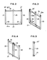
- Fig. 2 is a front view showing a pallet means of one embodiment of the present invention.
- Figs. 3 and 4 are perspective view corresponding to Fig. 2, but showing the pallet means from different directions.
- Fig. 5 is a sectional view taken on lines A - A of Fig. 2.
- Fig. 6 is a perspective view to help explain the operation of the pallet means of one embodiment of the present invention.
- An embodiment of the present invention will now be described by reference to Figs. 2 and 5.
- As shown, a pair of pallet means of the present invention each comprises a
bottom beam 21 andside beams bottom beam 21 andside beams bottom beam 21 has its opposite ends welded to one end of theside beam bottom beam 21 is placed perpendicular to theside beams face 21a of thebottom beam 21 is disposed within the same plane as those ofrespective faces side beams side beams upper beam 24 parallel to thebottom beam 21. Theupper beam 24, made of an L-shaped steel section, with an identical length to thebottom beam 21, is used to stiffen theside beams - The
bottom beam 21 also comprises locking means 30, 31 adapted to engage an inner surface of each longitudinal end of the lowermost-placed metal form. Locking means 30, 31 are in the form of locking fingers removably fitted adjacent each end of thebottom beam 21 where the latter joins theside beams bottom beam 21, giving the resulting clearance. Locking means 30, 31 are used to engage an interior surface of each longitudinal end of the lowest metal form to prevent slippage thereof. To meet such requirements, locking means 30, 31 should be long enough to engage an interior surface of the metal form, but smaller than the depth of the metal form to ensure a more positive retention. Although cylindrical-shaped locking means 30, 31 are shown, other shapes, such as square or plate-like fingers, may be used, so long as they are engageable with an interior surface of the metal form. - Similarly arranged locking means 30ʹ, 31ʹ are provided adjacent the opposite ends of an upper surface of the
bottom beam 24. When metal forms are desired to be moved in a stacked condition, locking means 30ʹ, 31ʹ are used to retain the upper tier of metal forms whether such forms are of identical or different length than the lower tier. - In addition, a
hooking beam 25, which is made of an L-shaped steel section, has one face welded to the bottom andupper beams side beams beam 25 also has acutout 26 formed on an upper end of the other face thereof and adapted to received a lifting hook connected to a wire rope. - Thus, the pallet means of the present invention has a lightweight design, weighing about a tenth the weight of conventional container means, for each member of the pair.
- Next, by reference to Fig. 6, the operation of the pallet means will be explained.
- Two
square timbers 40, 40ʹ are first placed in appropriate positions, on top of which metal forms are piled one above another, say, in two rows within a size defined by theupper beam 24,bottom beam 21 andside beams square timbers 40, 40ʹ are used to provide a spacing between the opposite longitudinal ends of metal forms and the ground, thereby allowing insertion of locking means 30, 31 for engaging the interior surface of the lowest metal form at each corner. Locking means 30, 31 are then inserted in place to engage the lowest metal form, while the pallet means are mounted on the metal forms so that the opposite lateral ends of the metal forms are covered byside beams slots hooking beams hooking slots hooking beams upper beam 24 serving as the fulcrum, thereby forcing the lower end ofrespective hooking beams bottom beans - Upon arrival at a destination, the metal forms are preferably placed on top of two square timbers, as is done before dispatch, to provide a spacing between the opposite ends of the metal form and the ground. Wire ropes are then untied from the
hooking holes - It will be understood that the pallet means of this invention presents no obstacle in loading or unloading the metal forms therewith, thereby speeding up the transport and use of metal forms. In addition, the lightweight design of the pallet means allows mechanized handling of just a few metal forms, instead of the use of manpower, thereby enhancing efficiency of the whole concrete pouring work. A pair of pallet means are spaced apart from each other to hold metal forms therebetween, allowing various lengths of metal forms; the pallet means is deformation-free during transport, leading to a prolonged life of the pallet; and the pallet means needs a minimum storage space when not in use.
Claims (1)
- A pallet means of transporting a pile of metal forms having a pair of means spaced apart from each other and adapted to hold the opposite lateral ends of metal forms, each member of said pair respectively comprising;
a bottom beam (21) for holding a lower end of said metal forms;
said beams mounted on each lateral end of said metal forms for retention thereof, wherein said bottom beam includes locking means (30,31) for engaging an interior surface of said metal form at each longitudinal end.
Applications Claiming Priority (2)
| Application Number | Priority Date | Filing Date | Title |
|---|---|---|---|
| JP1986177594U JPH0118530Y2 (en) | 1986-11-20 | 1986-11-20 | |
| JP177594/86U | 1986-11-20 |
Publications (3)
| Publication Number | Publication Date |
|---|---|
| EP0268300A2 true EP0268300A2 (en) | 1988-05-25 |
| EP0268300A3 EP0268300A3 (en) | 1989-03-15 |
| EP0268300B1 EP0268300B1 (en) | 1992-02-26 |
Family
ID=16033722
Family Applications (1)
| Application Number | Title | Priority Date | Filing Date |
|---|---|---|---|
| EP87117103A Expired - Lifetime EP0268300B1 (en) | 1986-11-20 | 1987-11-19 | Metal form pallet |
Country Status (4)
| Country | Link |
|---|---|
| US (1) | US4828311A (en) |
| EP (1) | EP0268300B1 (en) |
| JP (1) | JPH0118530Y2 (en) |
| DE (1) | DE3776867D1 (en) |
Cited By (1)
| Publication number | Priority date | Publication date | Assignee | Title |
|---|---|---|---|---|
| CN112875043A (en) * | 2021-01-27 | 2021-06-01 | 中国建筑第八工程局有限公司 | Packaging device and packaging method for folding steel support |
Families Citing this family (12)
| Publication number | Priority date | Publication date | Assignee | Title |
|---|---|---|---|---|
| AT1608U1 (en) * | 1996-08-22 | 1997-08-25 | Tonwerk Venus Gmbh | SUPPORT REINFORCEMENT FOR PRE-MADE CHIMNEY STRANDS |
| US5999584A (en) * | 1998-02-23 | 1999-12-07 | Framatome Technologies, Inc. | Reactor head lift apparatus |
| US6983704B1 (en) | 2003-01-31 | 2006-01-10 | Danny Ness | Offshore cargo rack for use in transferring palletized loads between a marine vessel and an offshore platform |
| US8104501B1 (en) | 2008-03-05 | 2012-01-31 | Ness Daniel W | Fluid handling system |
| US8231316B2 (en) | 2009-01-23 | 2012-07-31 | Danny Ness | Offshore cargo rack for use in transferring fluid holding tank loads between a marine vessel and an offshore platform |
| US9523250B2 (en) | 2009-11-17 | 2016-12-20 | Danny Ness | Mixing tank and method of use |
| US8875894B2 (en) | 2010-12-06 | 2014-11-04 | Danny Ness | Offshore cargo rack for use in transferring loads between a marine vessel and an offshore platform |
| BR112014015350A2 (en) | 2011-12-21 | 2017-06-13 | Ness Danny | cargo rack |
| WO2013185135A1 (en) | 2012-06-09 | 2013-12-12 | Danny Ness | Offshore cargo rack for use in transferring loads between a marine vessel and an offshore platform |
| US9346583B2 (en) | 2012-10-23 | 2016-05-24 | Tom Gurtner | Rack construction |
| US9216841B1 (en) | 2013-06-27 | 2015-12-22 | Daniel W. Ness | Offshore cargo rack for use in transferring palletized loads between a marine vessel and an offshore platform |
| WO2017069697A1 (en) * | 2015-10-21 | 2017-04-27 | Imh Equipment Pte Ltd | Lifting pallet |
Citations (3)
| Publication number | Priority date | Publication date | Assignee | Title |
|---|---|---|---|---|
| FR1040979A (en) * | 1951-12-21 | 1953-10-20 | Device facilitating the handling, transport and storage of rigid objects of thin or elongated shape | |
| GB1154247A (en) * | 1966-08-02 | 1969-06-04 | Foster Brothers Ltd | Improvements relating to Pallets |
| FR2259027A1 (en) * | 1974-01-30 | 1975-08-22 | Chapuis Transports | Support frame for transport of elongated tubes etc. - has hinged side member and removable top strut |
Family Cites Families (1)
| Publication number | Priority date | Publication date | Assignee | Title |
|---|---|---|---|---|
| US4518185A (en) * | 1983-09-19 | 1985-05-21 | Mcgraw-Edison Company | Die handling device |
-
1986
- 1986-11-20 JP JP1986177594U patent/JPH0118530Y2/ja not_active Expired
-
1987
- 1987-11-19 EP EP87117103A patent/EP0268300B1/en not_active Expired - Lifetime
- 1987-11-19 US US07/122,899 patent/US4828311A/en not_active Expired - Fee Related
- 1987-11-19 DE DE8787117103T patent/DE3776867D1/en not_active Expired - Fee Related
Patent Citations (3)
| Publication number | Priority date | Publication date | Assignee | Title |
|---|---|---|---|---|
| FR1040979A (en) * | 1951-12-21 | 1953-10-20 | Device facilitating the handling, transport and storage of rigid objects of thin or elongated shape | |
| GB1154247A (en) * | 1966-08-02 | 1969-06-04 | Foster Brothers Ltd | Improvements relating to Pallets |
| FR2259027A1 (en) * | 1974-01-30 | 1975-08-22 | Chapuis Transports | Support frame for transport of elongated tubes etc. - has hinged side member and removable top strut |
Cited By (1)
| Publication number | Priority date | Publication date | Assignee | Title |
|---|---|---|---|---|
| CN112875043A (en) * | 2021-01-27 | 2021-06-01 | 中国建筑第八工程局有限公司 | Packaging device and packaging method for folding steel support |
Also Published As
| Publication number | Publication date |
|---|---|
| EP0268300A3 (en) | 1989-03-15 |
| JPH0118530Y2 (en) | 1989-05-30 |
| JPS6382763U (en) | 1988-05-31 |
| US4828311A (en) | 1989-05-09 |
| EP0268300B1 (en) | 1992-02-26 |
| DE3776867D1 (en) | 1992-04-02 |
Similar Documents
| Publication | Publication Date | Title |
|---|---|---|
| US4191415A (en) | Storage and transportation apparatus | |
| US4828311A (en) | Metal form pallet | |
| US10550588B2 (en) | Peaked roofing pallets | |
| US5833289A (en) | Modular storage system for stacking cylindrical loads | |
| US2369944A (en) | Materials handling pallets adapted for use as accessories in fork lift truck operations | |
| US3430586A (en) | Nestable,corrugated forklift and sling pallet | |
| US4952114A (en) | Device for transporting adjusting frames for scaffolding | |
| US3827744A (en) | Process and apparatus for handling bulk building materials at construction sites | |
| US4529345A (en) | Cargo restraining device for high density loading of shipping drums | |
| US10745190B2 (en) | Transportable harp rack for panels | |
| US3511400A (en) | Nestable,corrugated forklift and sling pallet | |
| JPH07215655A (en) | Pallet device | |
| US5618153A (en) | Arrangement pertaining to the transportation of goods | |
| EP0860378A1 (en) | Container for holding and transporting crush barriers | |
| KR920005597Y1 (en) | Metal form pallet | |
| JP3336414B2 (en) | Handling equipment for long articles | |
| JPS628512Y2 (en) | ||
| JPH0672687A (en) | Container for thick plate | |
| JP3513073B2 (en) | Column-shaped product support member | |
| EP0004207A1 (en) | Apparatus for and method of stacking rectangular objects | |
| JPH07196281A (en) | Cradle | |
| SU1493551A1 (en) | Container | |
| GB2138774A (en) | Method of locating a container | |
| JPH1081331A (en) | Housing pan for lifting/lowering wooden pallet | |
| JPS58162439A (en) | Conveying and stacking method of long scale material and pallet device |
Legal Events
| Date | Code | Title | Description |
|---|---|---|---|
| PUAI | Public reference made under article 153(3) epc to a published international application that has entered the european phase |
Free format text: ORIGINAL CODE: 0009012 |
|
| AK | Designated contracting states |
Kind code of ref document: A2 Designated state(s): DE FR GB |
|
| PUAL | Search report despatched |
Free format text: ORIGINAL CODE: 0009013 |
|
| AK | Designated contracting states |
Kind code of ref document: A3 Designated state(s): DE FR GB |
|
| 17P | Request for examination filed |
Effective date: 19890605 |
|
| 17Q | First examination report despatched |
Effective date: 19901005 |
|
| GRAA | (expected) grant |
Free format text: ORIGINAL CODE: 0009210 |
|
| AK | Designated contracting states |
Kind code of ref document: B1 Designated state(s): DE FR GB |
|
| REF | Corresponds to: |
Ref document number: 3776867 Country of ref document: DE Date of ref document: 19920402 |
|
| ET | Fr: translation filed | ||
| PLBE | No opposition filed within time limit |
Free format text: ORIGINAL CODE: 0009261 |
|
| STAA | Information on the status of an ep patent application or granted ep patent |
Free format text: STATUS: NO OPPOSITION FILED WITHIN TIME LIMIT |
|
| 26N | No opposition filed | ||
| PGFP | Annual fee paid to national office [announced via postgrant information from national office to epo] |
Ref country code: GB Payment date: 19951101 Year of fee payment: 9 |
|
| PGFP | Annual fee paid to national office [announced via postgrant information from national office to epo] |
Ref country code: FR Payment date: 19951116 Year of fee payment: 9 |
|
| PGFP | Annual fee paid to national office [announced via postgrant information from national office to epo] |
Ref country code: DE Payment date: 19960129 Year of fee payment: 9 |
|
| PG25 | Lapsed in a contracting state [announced via postgrant information from national office to epo] |
Ref country code: GB Effective date: 19961119 |
|
| GBPC | Gb: european patent ceased through non-payment of renewal fee |
Effective date: 19961119 |
|
| PG25 | Lapsed in a contracting state [announced via postgrant information from national office to epo] |
Ref country code: FR Effective date: 19970731 |
|
| PG25 | Lapsed in a contracting state [announced via postgrant information from national office to epo] |
Ref country code: DE Effective date: 19970801 |
|
| REG | Reference to a national code |
Ref country code: FR Ref legal event code: ST |