EP0267958B1 - A mechanism for practice mines - Google Patents
A mechanism for practice mines Download PDFInfo
- Publication number
- EP0267958B1 EP0267958B1 EP87904002A EP87904002A EP0267958B1 EP 0267958 B1 EP0267958 B1 EP 0267958B1 EP 87904002 A EP87904002 A EP 87904002A EP 87904002 A EP87904002 A EP 87904002A EP 0267958 B1 EP0267958 B1 EP 0267958B1
- Authority
- EP
- European Patent Office
- Prior art keywords
- plunger
- arming
- mine
- catch plate
- release
- Prior art date
- Legal status (The legal status is an assumption and is not a legal conclusion. Google has not performed a legal analysis and makes no representation as to the accuracy of the status listed.)
- Expired
Links
Images


Classifications
-
- F—MECHANICAL ENGINEERING; LIGHTING; HEATING; WEAPONS; BLASTING
- F42—AMMUNITION; BLASTING
- F42B—EXPLOSIVE CHARGES, e.g. FOR BLASTING, FIREWORKS, AMMUNITION
- F42B8/00—Practice or training ammunition
- F42B8/28—Land or marine mines; Depth charges
Definitions
- the present invention relates to a mechanism assembly intended for practice mines of the kind which are intended to simulate a live mine and which comprise a mine body, the mechanism assembly comprising a mechanism housing mounted on the mine body and incorporating an axially movable and axially rotatable arming plunger which can be depressed manually from outside the mine, to obtain therewith an arming movement which simulates a desired arming function of the mine, and which further incorporates an axially movable release piston which can be depressed from outside of the mine and which is arranged to co-act operatively with the arming plunger in the depressed position thereof, in a manner to influence the arming movement of the plunger.
- a mechanism assembly intended for practice mines of the kind which are intended to simulate a live mine and which comprise a mine body
- the mechanism assembly comprising a mechanism housing mounted on the mine body and incorporating an axially movable and axially rotatable arming plunger which can be depressed manually from outside the mine, to obtain therewith an arming movement
- the object of the invention is therefore to provide a mechanism of the aforesaid kind which will function more reliably than the known mechanism, even after being repeatedly armed and disarmed, and which can be manufactured more readily than the aforesaid known mechanism.
- This object is achieved with a mechanism of the aforesaid kind that has the characterizing features set forth in Claim 1.
- Figure 1 illustrates a substantially hemispherical, empty metallic mine body 1 of the kind which is conventionally found with anti- tank mines and which, in accordance with the invention, forms the mine body of a practice mine which is intended preferably to be laid in a horizontal position.
- the outwardly facing circular orifice of the mine body is covered with a conventional metal cover member 2, the centrally located part of which, however, is modified in accordance with the invention to form a housing 3 which accommodates the inventive mechanism.
- An axially rotatable metallic arming plunger 4 is mounted for axial movement in a bush 5 located in an outer wall 3a of the housing 3, and can be depressed into the housing against the action of a first thrust or compression spring 6.
- the arming plunger 4 consists of an elongated member having a first, cylindrical end-part 4a, which is mounted for axial movement in the bush 5, and intermediate part 4b, which has a rectangular shape in cross-section and which tapers at one end thereof remote from said first end-part 4a into a cylindrical second end-part 4c of smaller diameter of the first mentioned end-part 4a.
- a metal catch plate 7 (c.f. also Figure 3) is non-rotatably connected with the intermediate part 4b of the plunger 4 and extends transversely in relation thereto.
- the non-rotatable connection is achieved through the combination of a non-round aperture provided in the catch plate 7, in the illustrated embodiment an essentially elongated rectangular aperture 8, and an intermediate plunger-part 4b which is of corresponding non-round shape and passes freely through said aperture.
- the catch plate 7 is held axially in place on the intermediate part 4b of the plunger 4 through the abutment of its one, upper side with the bottom surface of the end-part 4a, which therewith forms a supporting shoulder, and through the supporting action of a locking pin 9 which is passed through a hole 10 located in the intermediate part, on the under side of the catch plate.
- the second end-part 4c of the arming plunger 4 is displaceable axially through a hole located in an inner wall 3b of the housing 3.
- the spring 6 therewith encircles the second end-part 4c of the plunger, with the lower end of the spring supported against the radially inner wall 3b of the housing.
- the upper end of the spring 6 bears forcibly against one end of a bearing sleeve 11 which fits over the second end-part 4c of the plunger and is movable axially therealong.
- the other end of the sleeve abuts the under-surface of the catch plate 7.
- the uppersurface of the catch plate 7 is engaged in a horizontally positioned catch plate groove or channel 12 (c.f. Figure 4) provided in the inwardly facing surface of the radially outer wall 3a of the housing 3 ( Figure I), the spring 6 thus striving to hold the catch plates 7 firmly in the groove 12.
- the groove 12 is inclined at an angle v of about 45° towards a metallic release plunger 13, for reasons hereinafter made apparent.
- the release plunger 13 extends parallel with the arming plunger 4 and is mounted for axial movement in the outer wall 3a of the housing 3, depression of the release plunger into the housing being effected against the action of a second thrust or compression spring 14.
- the release plunger 13 consists of an elongated member having a first cylindrical upper end-part 13a, which is mounted for axial movement in a bush 15 provided in the outer wall 3a of the housing 3, a cylindrical intermediate part 13b of smaller diameter than the end-part 13a, and a second cylindrical end-part 13c, a lower end-part, whose diameter is smaller than the diameter of the intermediate part 13b.
- the second end-part 13c of the release plunger 13 is mounted for axial movement in a hole provided in the innerwaii 3b of the housing 3.
- the spring 14 thus encircles the second end-part 13c of said release plunger and is held with the lower end of the spring in abutment with the inner wall 3b of the housing and with the upper end of the spring bearing forcibly against the adjacent end of a first latching device, in the form of a locking sleeve 16 which is fitted over the second end-part 13c and is axially movable therealong.
- the locking sleeve 16 accommodates a second latching device, in the form of a latching sleeve 17 having a conically bevelled upper end which abuts the outer wall 3a of the housing 3.
- the latching sleeve 17 is held in position on the end-part 13c of the release plunger, by means of a locking pin 18 which is inserted through respective holes located in the end-part 13c and the latching sleeve 17, so as to extend transversely to the longitudinal centres thereof.
- Unintentional or accidental depression of the arming plunger 4 and the release plunger 13 is prevented by a rod-shaped safety device 19 which when it its safe, transportation position lies between the upper surface of the outer wall 3a of the housing 3 and the under surface of an arming device 4d, such as an arming lever, located on the arming plunger 4, and the under surface of a circular head 13d on the release plunger 13.
- the arming device 4d and the release head 13d thus constitute actuating means by means of which the mine can be activated manually from outside the mine, so as to obtain the desired simulated arming function.
- the mechanism operates in the following manner.
- the release plunger is moved axially downwards so that the catch plate becomes free from the locking sleeve 16 and so that the bevelled surface on the latching sleeve 17 is located centrally opposite the catch plate 7 instead.
- the arming lever 4d can now be turned until the catch plate 7 has been rotated through about 90-95°, wherewith the catch plate is brought into contact with the bevelled part of the latching sleeve 17.
- the spring 14 effects a wedging action which holds the catch plate 7 firmly against the bevelled part of the latching sleeve 17, as illustrated in Figure 5.
- the mine is now in its simulated armed state.
- the catch plate arrangement and the co-action of the catch plate 7 with the release plunger 13 provides a particularly reliable mechanism which can be armed and disarmed repeatedly a great many times without malfunctioning.
- the inventive mechanism forms part of a conventional lid or cover member of a mine body.
- the mechanism assembly may alternatively form a separate unit which is mounted on the mine body or on the cover member thereof.
Landscapes
- Engineering & Computer Science (AREA)
- Ocean & Marine Engineering (AREA)
- General Engineering & Computer Science (AREA)
- Devices For Conveying Motion By Means Of Endless Flexible Members (AREA)
- Actuator (AREA)
- Transmission Devices (AREA)
- Mechanical Control Devices (AREA)
- Snaps, Bayonet Connections, Set Pins, And Snap Rings (AREA)
- Toys (AREA)
Abstract
Description
- The present invention relates to a mechanism assembly intended for practice mines of the kind which are intended to simulate a live mine and which comprise a mine body, the mechanism assembly comprising a mechanism housing mounted on the mine body and incorporating an axially movable and axially rotatable arming plunger which can be depressed manually from outside the mine, to obtain therewith an arming movement which simulates a desired arming function of the mine, and which further incorporates an axially movable release piston which can be depressed from outside of the mine and which is arranged to co-act operatively with the arming plunger in the depressed position thereof, in a manner to influence the arming movement of the plunger. Such a device is well known in practice and belongs to the state of the art according to Article 54(2).
- With practice or training mines of this kind the torque prevailing at the terminal positions of the axially rotatable arming plunger is taken up by a cylindrical locking pin that passes through a hole extending radially through the arming plunger. It has been found, however, that repeated arming and disarming of the mechanism is liable to result in wear on the hole, such that the pin will not be held firmly therein, due to the resultant clearance between the pin and the hole-defining surfaces, with the accompanying risk that the pin may loosen and fall away.
- Another drawback with known practice mines of this kind is that the provision of the grooves required in the mechanism housing to accommodate and guide the terminal positions of the pin is both difficult and extensive.
- The object of the invention is therefore to provide a mechanism of the aforesaid kind which will function more reliably than the known mechanism, even after being repeatedly armed and disarmed, and which can be manufactured more readily than the aforesaid known mechanism. This object is achieved with a mechanism of the aforesaid kind that has the characterizing features set forth in Claim 1.
- Further features of the invention are set forth in the depending claims.
- The invention will now be described in more detail with reference to the accompanying drawings, which illustrate a preferred embodiment of the inventive mechanism assembly.
- Figure 1 is a cross-sectional view of a practice mine fitted with the inventive mechanism assembly.
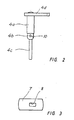
- Figure 2 is a side view of an arming plunger incorporated in the mechanism assembly illustrated in Figure 1.
- Figure 3 is a plan view of a catch plate incorporated in the mechanism illustrated in Figure 1.
- Figure 4 is a cross-sectional view taken on the line IV-IV in Figure 1 and turned through 45°, and illustrates the arming plunger in a disarming or safe position.
- Figure 5 is a cross-sectional view similar to that of Figure 4 but with the arming plunger shown in its arming position.
- Figure 1 illustrates a substantially hemispherical, empty metallic mine body 1 of the kind which is conventionally found with anti- tank mines and which, in accordance with the invention, forms the mine body of a practice mine which is intended preferably to be laid in a horizontal position. The outwardly facing circular orifice of the mine body is covered with a conventional metal cover member 2, the centrally located part of which, however, is modified in accordance with the invention to form a housing 3 which accommodates the inventive mechanism. An axially rotatable metallic arming plunger 4 is mounted for axial movement in a bush 5 located in an
outer wall 3a of the housing 3, and can be depressed into the housing against the action of a first thrust orcompression spring 6. - As will be seen more clearly from Figure 2, the arming plunger 4 consists of an elongated member having a first, cylindrical end-
part 4a, which is mounted for axial movement in the bush 5, and intermediate part 4b, which has a rectangular shape in cross-section and which tapers at one end thereof remote from said first end-part 4a into a cylindrical second end-part 4c of smaller diameter of the first mentioned end-part 4a. - A metal catch plate 7 (c.f. also Figure 3) is non-rotatably connected with the intermediate part 4b of the plunger 4 and extends transversely in relation thereto. In the case of the illustrated embodiment (c.f. in particular Figures 1 and 3) the non-rotatable connection is achieved through the combination of a non-round aperture provided in the
catch plate 7, in the illustrated embodiment an essentially elongatedrectangular aperture 8, and an intermediate plunger-part 4b which is of corresponding non-round shape and passes freely through said aperture. Thecatch plate 7 is held axially in place on the intermediate part 4b of the plunger 4 through the abutment of its one, upper side with the bottom surface of the end-part 4a, which therewith forms a supporting shoulder, and through the supporting action of a locking pin 9 which is passed through ahole 10 located in the intermediate part, on the under side of the catch plate. - The second end-
part 4c of the arming plunger 4 is displaceable axially through a hole located in aninner wall 3b of the housing 3. Thespring 6 therewith encircles the second end-part 4c of the plunger, with the lower end of the spring supported against the radiallyinner wall 3b of the housing. The upper end of thespring 6 bears forcibly against one end of abearing sleeve 11 which fits over the second end-part 4c of the plunger and is movable axially therealong. The other end of the sleeve abuts the under-surface of thecatch plate 7. The uppersurface of thecatch plate 7 is engaged in a horizontally positioned catch plate groove or channel 12 (c.f. Figure 4) provided in the inwardly facing surface of the radiallyouter wall 3a of the housing 3 (Figure I), thespring 6 thus striving to hold thecatch plates 7 firmly in thegroove 12. - As illustrated, the
groove 12 is inclined at an angle v of about 45° towards a metallic release plunger 13, for reasons hereinafter made apparent. The release plunger 13 extends parallel with the arming plunger 4 and is mounted for axial movement in theouter wall 3a of the housing 3, depression of the release plunger into the housing being effected against the action of a second thrust orcompression spring 14. - Similar to the arming plunger 4, the release plunger 13 consists of an elongated member having a first cylindrical upper end-
part 13a, which is mounted for axial movement in a bush 15 provided in theouter wall 3a of the housing 3, a cylindricalintermediate part 13b of smaller diameter than the end-part 13a, and a second cylindrical end-part 13c, a lower end-part, whose diameter is smaller than the diameter of theintermediate part 13b. - The second end-
part 13c of the release plunger 13 is mounted for axial movement in a hole provided in theinnerwaii 3b of the housing 3. Thespring 14 thus encircles the second end-part 13c of said release plunger and is held with the lower end of the spring in abutment with theinner wall 3b of the housing and with the upper end of the spring bearing forcibly against the adjacent end of a first latching device, in the form of alocking sleeve 16 which is fitted over the second end-part 13c and is axially movable therealong. - The
locking sleeve 16 accommodates a second latching device, in the form of a latching sleeve 17 having a conically bevelled upper end which abuts theouter wall 3a of the housing 3. The latching sleeve 17 is held in position on the end-part 13c of the release plunger, by means of alocking pin 18 which is inserted through respective holes located in the end-part 13c and the latching sleeve 17, so as to extend transversely to the longitudinal centres thereof. - Unintentional or accidental depression of the arming plunger 4 and the release plunger 13 is prevented by a rod-
shaped safety device 19 which when it its safe, transportation position lies between the upper surface of theouter wall 3a of the housing 3 and the under surface of anarming device 4d, such as an arming lever, located on the arming plunger 4, and the under surface of acircular head 13d on the release plunger 13. Thearming device 4d and therelease head 13d thus constitute actuating means by means of which the mine can be activated manually from outside the mine, so as to obtain the desired simulated arming function. - The mechanism operates in the following manner.
- When the arming plunger 4 is depressed, by activating the
arming lever 4d, thecatch plate 7 is automatically moved out of the catch-plate groove 12 located in thewall 3a of the housing 3. It is still not possible, however, to turn thelever 4d, due to the fact that in this position the catch plate is still in abutment with an edge part of thelocking sleeve 16 on the release plunger 13, as a result of the inclination of thegroove 12. This latching action is clearly shown in Figure 4. However, by depressing therelease head 13d, and therewith also the release piston 13, the release plunger is moved axially downwards so that the catch plate becomes free from thelocking sleeve 16 and so that the bevelled surface on the latching sleeve 17 is located centrally opposite thecatch plate 7 instead. Thearming lever 4d can now be turned until thecatch plate 7 has been rotated through about 90-95°, wherewith the catch plate is brought into contact with the bevelled part of the latching sleeve 17. When the pressure on therelease head 13d is removed, thespring 14 effects a wedging action which holds thecatch plate 7 firmly against the bevelled part of the latching sleeve 17, as illustrated in Figure 5. The mine is now in its simulated armed state. - The catch plate arrangement and the co-action of the
catch plate 7 with the release plunger 13 provides a particularly reliable mechanism which can be armed and disarmed repeatedly a great many times without malfunctioning. - In the illustrated embodiment the inventive mechanism forms part of a conventional lid or cover member of a mine body. Although not shown, the mechanism assembly may alternatively form a separate unit which is mounted on the mine body or on the cover member thereof.
Claims (7)
Applications Claiming Priority (2)
| Application Number | Priority Date | Filing Date | Title |
|---|---|---|---|
| SE8602480 | 1986-06-02 | ||
| SE8602480A SE453534B (en) | 1986-06-02 | 1986-06-02 | MECHANISM OF AN EXERCISMINA |
Publications (2)
| Publication Number | Publication Date |
|---|---|
| EP0267958A1 EP0267958A1 (en) | 1988-05-25 |
| EP0267958B1 true EP0267958B1 (en) | 1990-04-25 |
Family
ID=20364699
Family Applications (1)
| Application Number | Title | Priority Date | Filing Date |
|---|---|---|---|
| EP87904002A Expired EP0267958B1 (en) | 1986-06-02 | 1987-05-25 | A mechanism for practice mines |
Country Status (4)
| Country | Link |
|---|---|
| US (1) | US4850276A (en) |
| EP (1) | EP0267958B1 (en) |
| SE (1) | SE453534B (en) |
| WO (1) | WO1987007710A1 (en) |
Families Citing this family (3)
| Publication number | Priority date | Publication date | Assignee | Title |
|---|---|---|---|---|
| SE501497C2 (en) * | 1993-03-11 | 1995-02-27 | Ralph H Widenbaeck | Exercise mine and ways to slowly activate it |
| GB9410594D0 (en) * | 1994-05-26 | 1994-07-13 | Kenton Ranssord A | Harmless spray etc producing devices |
| US8887548B1 (en) * | 2012-08-22 | 2014-11-18 | The United States Of America As Represented By The Secretary Of The Navy | Land mine simulator |
Family Cites Families (4)
| Publication number | Priority date | Publication date | Assignee | Title |
|---|---|---|---|---|
| FR864354A (en) * | 1940-03-26 | 1941-04-25 | A & L Guillouard | Land mine with circular plate trigger |
| EP0119383B1 (en) * | 1983-01-12 | 1987-05-06 | NICO-PYROTECHNIK Hanns-Jürgen Diederichs GmbH & Co. KG | Ignition device |
| DE3424698A1 (en) * | 1984-07-05 | 1986-01-16 | Honeywell Gmbh, 6050 Offenbach | Safety device for fuses |
| GB2165928B (en) * | 1984-10-22 | 1988-05-25 | Honeywell Leafield Ltd | Mine simulator |
-
1986
- 1986-06-02 SE SE8602480A patent/SE453534B/en not_active IP Right Cessation
-
1987
- 1987-05-25 WO PCT/SE1987/000259 patent/WO1987007710A1/en not_active Ceased
- 1987-05-25 US US07/145,779 patent/US4850276A/en not_active Expired - Fee Related
- 1987-05-25 EP EP87904002A patent/EP0267958B1/en not_active Expired
Also Published As
| Publication number | Publication date |
|---|---|
| SE8602480L (en) | 1987-12-03 |
| SE453534B (en) | 1988-02-08 |
| SE8602480D0 (en) | 1986-06-02 |
| US4850276A (en) | 1989-07-25 |
| EP0267958A1 (en) | 1988-05-25 |
| WO1987007710A1 (en) | 1987-12-17 |
Similar Documents
| Publication | Publication Date | Title |
|---|---|---|
| US5166458A (en) | Firing mechanism for fast shooting pistol | |
| US4536983A (en) | Reloader for muzzle loaders | |
| US4007563A (en) | Deck anchor | |
| US4188856A (en) | Compressed-gas-actuated switching device | |
| US4302898A (en) | Individual safety firing button for guns | |
| US4793063A (en) | Punch gun | |
| US3998124A (en) | Bomb rack arming unit | |
| US5013197A (en) | Locking bolt for equipment support | |
| US4850276A (en) | Mechanism for practice mines | |
| US20180289153A1 (en) | Firearm Locking and Restraining System | |
| US3994227A (en) | Bounding anti-personnel mine | |
| US4040196A (en) | Rifle | |
| US4523731A (en) | External store release for flight vehicle | |
| DE2423912A1 (en) | Safety mechanism for land mines - has arming and safety devices feature for recovery of armed mines | |
| US7444893B2 (en) | Booster actuator | |
| EP0156763A1 (en) | Method and device for increasing the energy in an electromagnetic fuze system | |
| US2935949A (en) | Combination mine fuze | |
| US3272125A (en) | Three-way fuze | |
| US3884151A (en) | Detonator for land mines | |
| DE102023004551B4 (en) | Device for securing, arming and firing ammunition, and ammunition system | |
| DE1921317C3 (en) | Electromagnetic ignition generator | |
| DE3709235A1 (en) | Safety device for mine detonators | |
| SU1022175A1 (en) | Interlocking device | |
| DE2645914C3 (en) | Sound signal body for underwater sound signal generation | |
| DE1275427B (en) | Trigger for fireworks rockets |
Legal Events
| Date | Code | Title | Description |
|---|---|---|---|
| PUAI | Public reference made under article 153(3) epc to a published international application that has entered the european phase |
Free format text: ORIGINAL CODE: 0009012 |
|
| 17P | Request for examination filed |
Effective date: 19880208 |
|
| AK | Designated contracting states |
Kind code of ref document: A1 Designated state(s): DE NL |
|
| 17Q | First examination report despatched |
Effective date: 19890419 |
|
| GRAA | (expected) grant |
Free format text: ORIGINAL CODE: 0009210 |
|
| AK | Designated contracting states |
Kind code of ref document: B1 Designated state(s): DE NL |
|
| REF | Corresponds to: |
Ref document number: 3762454 Country of ref document: DE Date of ref document: 19900531 |
|
| PLBE | No opposition filed within time limit |
Free format text: ORIGINAL CODE: 0009261 |
|
| STAA | Information on the status of an ep patent application or granted ep patent |
Free format text: STATUS: NO OPPOSITION FILED WITHIN TIME LIMIT |
|
| 26N | No opposition filed | ||
| PGFP | Annual fee paid to national office [announced via postgrant information from national office to epo] |
Ref country code: NL Payment date: 19910531 Year of fee payment: 5 |
|
| PGFP | Annual fee paid to national office [announced via postgrant information from national office to epo] |
Ref country code: DE Payment date: 19910625 Year of fee payment: 5 |
|
| PG25 | Lapsed in a contracting state [announced via postgrant information from national office to epo] |
Ref country code: NL Effective date: 19921201 |
|
| NLV4 | Nl: lapsed or anulled due to non-payment of the annual fee | ||
| PG25 | Lapsed in a contracting state [announced via postgrant information from national office to epo] |
Ref country code: DE Effective date: 19930202 |