EP0267550B1 - Adjustable tilt/swivel/mounting assembly - Google Patents
Adjustable tilt/swivel/mounting assembly Download PDFInfo
- Publication number
- EP0267550B1 EP0267550B1 EP87116393A EP87116393A EP0267550B1 EP 0267550 B1 EP0267550 B1 EP 0267550B1 EP 87116393 A EP87116393 A EP 87116393A EP 87116393 A EP87116393 A EP 87116393A EP 0267550 B1 EP0267550 B1 EP 0267550B1
- Authority
- EP
- European Patent Office
- Prior art keywords
- plate
- platform
- mounting assembly
- base
- axis
- Prior art date
- Legal status (The legal status is an assumption and is not a legal conclusion. Google has not performed a legal analysis and makes no representation as to the accuracy of the status listed.)
- Expired - Lifetime
Links
- 230000005484 gravity Effects 0.000 claims description 2
- 230000000712 assembly Effects 0.000 description 1
- 238000000429 assembly Methods 0.000 description 1
- 238000010276 construction Methods 0.000 description 1
Images


Classifications
-
- F—MECHANICAL ENGINEERING; LIGHTING; HEATING; WEAPONS; BLASTING
- F16—ENGINEERING ELEMENTS AND UNITS; GENERAL MEASURES FOR PRODUCING AND MAINTAINING EFFECTIVE FUNCTIONING OF MACHINES OR INSTALLATIONS; THERMAL INSULATION IN GENERAL
- F16M—FRAMES, CASINGS OR BEDS OF ENGINES, MACHINES OR APPARATUS, NOT SPECIFIC TO ENGINES, MACHINES OR APPARATUS PROVIDED FOR ELSEWHERE; STANDS; SUPPORTS
- F16M11/00—Stands or trestles as supports for apparatus or articles placed thereon ; Stands for scientific apparatus such as gravitational force meters
- F16M11/02—Heads
- F16M11/04—Means for attachment of apparatus; Means allowing adjustment of the apparatus relatively to the stand
- F16M11/06—Means for attachment of apparatus; Means allowing adjustment of the apparatus relatively to the stand allowing pivoting
- F16M11/12—Means for attachment of apparatus; Means allowing adjustment of the apparatus relatively to the stand allowing pivoting in more than one direction
- F16M11/126—Means for attachment of apparatus; Means allowing adjustment of the apparatus relatively to the stand allowing pivoting in more than one direction for tilting and panning
-
- F—MECHANICAL ENGINEERING; LIGHTING; HEATING; WEAPONS; BLASTING
- F16—ENGINEERING ELEMENTS AND UNITS; GENERAL MEASURES FOR PRODUCING AND MAINTAINING EFFECTIVE FUNCTIONING OF MACHINES OR INSTALLATIONS; THERMAL INSULATION IN GENERAL
- F16M—FRAMES, CASINGS OR BEDS OF ENGINES, MACHINES OR APPARATUS, NOT SPECIFIC TO ENGINES, MACHINES OR APPARATUS PROVIDED FOR ELSEWHERE; STANDS; SUPPORTS
- F16M2200/00—Details of stands or supports
- F16M2200/08—Foot or support base
-
- Y—GENERAL TAGGING OF NEW TECHNOLOGICAL DEVELOPMENTS; GENERAL TAGGING OF CROSS-SECTIONAL TECHNOLOGIES SPANNING OVER SEVERAL SECTIONS OF THE IPC; TECHNICAL SUBJECTS COVERED BY FORMER USPC CROSS-REFERENCE ART COLLECTIONS [XRACs] AND DIGESTS
- Y10—TECHNICAL SUBJECTS COVERED BY FORMER USPC
- Y10S—TECHNICAL SUBJECTS COVERED BY FORMER USPC CROSS-REFERENCE ART COLLECTIONS [XRACs] AND DIGESTS
- Y10S248/00—Supports
- Y10S248/917—Video display screen support
- Y10S248/919—Adjustably orientable video screen support
- Y10S248/921—Plural angular
Definitions
- the invention relates to a mounting assembly for an apparatus like a monitor as disclosed in DE-A 3 402 821 and allowing for rotation about a vertical axis and tilting about a horizontal axis.
- planar surfaces for cooperation with corresponding planar surfaces at a spherical platform are provided at a slide element mounted above a base.
- Mounting assemblies for this purpose have been comprised of a base that can be secured to a table top and a platform on which the apparatus is mounted that can be tilted and swiveled with respect to the base. These functions are provided by a spherically shaped bottom surface on the platform that rests in an upwardly extending annular ridge on the base and a straight slot in the spherical bottom of the platform through which a vertical pivot pin that is rigidly mounted to the base extends.
- the platform can only be tilted in the vertical plane of the slot and can be rotated about the pivot pin regardless of where it is in the slot.
- Leads or tubes required for operation of the apparatus are passed between the apparatus and the platform, through an aperture in the bottom spherical surface and an opening in the base that lies inside the annular ridge.
- the amount of swivel is limited by the leads coming in contact with an edge of the opening in the base. This is undesirable as sufficient force can easily be applied to the leads to cause them to be pulled loose.
- the angle through which the platform can be swiveled is limited if the pivot pin is to be inexpensively and securely mounted. Any arrangement of simple means for limiting the angle of swivel so as to avoid contact between the wires and tubes and the edges of the opening in the base is complicated by the tilting of the platform with respect to the base.
- the vertical plane of the tilt is determined by the pin sliding in the slot and the vertical axis about which the platform swivel is the axis of the pin.
- the problem underlying the invention is to provide a mounting assembly for an apparatus like a monitor which allows for a simple construction and assembling/ disassembling.
- a downwardly extending annular ridge is formed on the underside of the base that is coaxial with an upwardly extending annular ridge thereon, and a plate is provided having tabs that contact the downwardly extending annular ridge at various points about its periphery so that the axis of rotation of the plate is the common axis of the annular ridges.
- Means are provided for keeping the plate in contact with the base. This could be accomplished by a pin mounted on the plate and extending through a slot in the spherical bottom surface of the platform but other means could be used, e.g., the plate could rest on the table top in which the base is mounted.
- Leads for the apparatus are entrained between the platform and the base, through ports in the spherical bottom of the platform, through an opening in the base that is within the annular ridges and through an aperture in the plate.
- Restriction of the plane on which the platform is tilted as well as swiveling the plate with the the platform is preferably attained by the sliding action between at least one straight vertical surface extending from the spherical bottom surface of the platform and a straight vertical surface on said plate.
- vertical sleeve-like extensions from the edges of the port are provided that are long enough to pass through the aperture in the plate that is in registration with them. The platform can be made to tilt until an extension strikes the edge of the aperture.
- the maximum amount of swivel can be set at nearly one revolution by interference between an outwardly extending tab and a stop on the base.
- a base B that maybe vacuum formed from plastic has a circular opening 0 surrounded by a downwardly extending annular ridge r 1 .
- a mounting bracket b having outwardly extending flanges f 1 and f 2 is fastened in any suitable manner to the underside of the base B.
- a plate Pi has upwardly extending tabs 2,4,6 and 8 that contact the outside of the ridge r 1 .
- a platform P 2 has a downwardly extending spherical thin wall W. A central radius of the wall W coincides with an axis 10 of the circular opening 0 in the base B when the platform P 2 is in a horizontal position.
- the spherical wall W rests on an annular ridge r 2 shown by a dashed line in FIG 1.
- the ridge r 2 extends upwardly from the base B and is concentric with the downwardly extending ridge ri.
- a straight slit S is formed through the wall W that extends through the axis 10.
- Ports p i and p 2 are formed on either side of the slit S.
- Extensions e 1 and e 2 respectively extend downwardly from the edges of the ports p 1 and p 2 .
- the extensions e 1 and e 2 pass through the opening 0 in the base B and into apertures a 1 and a 2 in the plate P i .
- a monitor M or other apparatus is mounted on the platform P 2 in any suitable manner with its center of gravity preferably in a plane perpendicular to the direction of tilt, passing through the axis 10 and no higher than the center of rotation of the spherical surface W.
- the monitor M is turned about the axis 10 or tilted, the spherical wall W slides on the annular ridge r 2 as required.
- FIG 2 is a cross-section of the parts just described when they are assembled and is taken through the axis 10 and perpendicular to the middle of the slit S.
- a stud s that is fastened to the center of the plate P 1 extends upwardly along the axis 10 through the opening 0 in the base B and through the slit S, and a head h is screwed into the stud s so as to prevent the stud from being drawn through the slit S.
- Upwardly extending flanges f 3 , f 4 , fs and f 6 are formed along the edges of the apertures a 1 and a 2 in Pi respectively, and the extensions e1 and e 2 snugly fit inside of them so that rotation of the platform P 2 on which M is mounted causes the plate Pi to rotate also.
- a tab 12 is provided that extends outwardly from one corner of the plate P 1 so as to strike a tab 14 on the underside of the bracket b at one point in the revolution of Pi.
- the bracket b is annular and is attached to the base B by any such means such as bolts 16 and 18. If desired, a number of rubber feet such as 20 and 22 can be attached in any suitable manner to the flanges fi and f 2 of the bracket b.
- the means for mounting the monitor M on the upper side of the platform P 2 is shown as being a third plate Ps having downwardly extending angles 24 and 26 that fit inside and touch a ridge r that extends upwardly from the platform P 2 .
- a break 28 in the ridge r and a notch n in the third plate Ps provide a path through which leads, not shown, from the back 30 of the monitor M may be passed into the upper side of the spherical wall or shell W. From there they can be passed through the ports pi and p 2 , the extensions e 1 and e 2 , the apertures a 1 and a 2 in the plate Pi and through the opening 0 that is within the annular ridges r 1 and r 2 .
- the bracket b ma y be secured by screws to a table top 32 in a location such that the opening 0 in the base B is axially aligned with an opening O' in the table 32.
- the flanges fs, f 4 , fs, and f 6 form planar surfaces that are perpendicular to a radius from the axis 10 and respectively in sliding surface to surface contact with planar surfaces on the adjacent respective sides of the sleeve-like extensions e 1 and e 2 .
- the surface to surface contact of the planar surfaces causes the plate P 1 to rotate about the axis 10 with the platform P 2 , and the tab 12 and projection 14 limit the swivel to slightly less than one turn. The amount of tilt is limited in this embodiment by the stud s striking the ends of the slot S.
- the tilt could be limited by the extension e 1 and e 2 striking the ridge r 2 in which event, the stud or pin s would prevent the assembly from being pulled apart if one were to attempt to lift the platform P 2 or to tilt the platform P 2 too far. Because the plate Pi determines the axis of rotation of the platform P 2 , the stud s does not need to be circular in cross-section as in the prior art.
- the wires from the apparatus M pass through the notch n in between M and the platform P 2 through one or both extensions e 1 and e 2 through opening O and either or both of the apertures a 1 and a 2 .
Landscapes
- Engineering & Computer Science (AREA)
- General Engineering & Computer Science (AREA)
- Mechanical Engineering (AREA)
- Pivots And Pivotal Connections (AREA)
- Casings For Electric Apparatus (AREA)
- Devices For Indicating Variable Information By Combining Individual Elements (AREA)
Description
- The invention relates to a mounting assembly for an apparatus like a monitor as disclosed in DE-A 3 402 821 and allowing for rotation about a vertical axis and tilting about a horizontal axis.
- In the known mounting assembly planar surfaces for cooperation with corresponding planar surfaces at a spherical platform are provided at a slide element mounted above a base.
- It is often desirable to be able to easily tilt certain types of apparatus in a given plane and to swivel it about a vertical axis in order to make it easier to see images formed thereon and to adjust various controls. Mounting assemblies for this purpose have been comprised of a base that can be secured to a table top and a platform on which the apparatus is mounted that can be tilted and swiveled with respect to the base. These functions are provided by a spherically shaped bottom surface on the platform that rests in an upwardly extending annular ridge on the base and a straight slot in the spherical bottom of the platform through which a vertical pivot pin that is rigidly mounted to the base extends. The platform can only be tilted in the vertical plane of the slot and can be rotated about the pivot pin regardless of where it is in the slot. Leads or tubes required for operation of the apparatus are passed between the apparatus and the platform, through an aperture in the bottom spherical surface and an opening in the base that lies inside the annular ridge. The amount of swivel is limited by the leads coming in contact with an edge of the opening in the base. This is undesirable as sufficient force can easily be applied to the leads to cause them to be pulled loose. Furthermore, the angle through which the platform can be swiveled is limited if the pivot pin is to be inexpensively and securely mounted. Any arrangement of simple means for limiting the angle of swivel so as to avoid contact between the wires and tubes and the edges of the opening in the base is complicated by the tilting of the platform with respect to the base.
- It is to be noted that in the apparatus of the prior art briefly described above, the vertical plane of the tilt is determined by the pin sliding in the slot and the vertical axis about which the platform swivel is the axis of the pin.
- The problem underlying the invention is to provide a mounting assembly for an apparatus like a monitor which allows for a simple construction and assembling/ disassembling.
- This problem is accomplished by claim 1.
- According to this invention, a downwardly extending annular ridge is formed on the underside of the base that is coaxial with an upwardly extending annular ridge thereon, and a plate is provided having tabs that contact the downwardly extending annular ridge at various points about its periphery so that the axis of rotation of the plate is the common axis of the annular ridges. Means are provided for keeping the plate in contact with the base. This could be accomplished by a pin mounted on the plate and extending through a slot in the spherical bottom surface of the platform but other means could be used, e.g., the plate could rest on the table top in which the base is mounted.
- Leads for the apparatus are entrained between the platform and the base, through ports in the spherical bottom of the platform, through an opening in the base that is within the annular ridges and through an aperture in the plate.
- Restriction of the plane on which the platform is tilted as well as swiveling the plate with the the platform is preferably attained by the sliding action between at least one straight vertical surface extending from the spherical bottom surface of the platform and a straight vertical surface on said plate. In a preferred embodiment vertical sleeve-like extensions from the edges of the port are provided that are long enough to pass through the aperture in the plate that is in registration with them. The platform can be made to tilt until an extension strikes the edge of the aperture.
- Since the plate rotates with the platform but does not tilt, the maximum amount of swivel can be set at nearly one revolution by interference between an outwardly extending tab and a stop on the base.
-
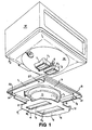
- FIG 1 is an exploded view of the mountin g assembly with a view into the bottom side of the spherical wall of the platform;
- FIG 2 is a cross-sectional view taken perpendicular to the axis of the annular ridges and perpendicular to the radial slit, and;
- FIG 3 is an exploded view of the mounting assembly with a view into the upper side of the spherical wall of the platform.
- The components of the assembly are designated in the same manner in each Figure of the drawings. A base B that maybe vacuum formed from plastic has a circular opening 0 surrounded by a downwardly extending annular ridge r1. A mounting bracket b having outwardly extending flanges f1 and f2 is fastened in any suitable manner to the underside of the base B. A plate Pi has upwardly extending
tabs axis 10 of the circular opening 0 in the base B when the platform P2 is in a horizontal position. The spherical wall W rests on an annular ridge r2 shown by a dashed line in FIG 1. The ridge r2 extends upwardly from the base B and is concentric with the downwardly extending ridge ri. A straight slit S is formed through the wall W that extends through theaxis 10. Ports pi and p2 are formed on either side of the slit S. Extensions e1 and e2 respectively extend downwardly from the edges of the ports p1 and p2. The extensions e1 and e2 pass through the opening 0 in the base B and into apertures a1 and a2 in the plate Pi. A monitor M or other apparatus is mounted on the platform P2 in any suitable manner with its center of gravity preferably in a plane perpendicular to the direction of tilt, passing through theaxis 10 and no higher than the center of rotation of the spherical surface W. As the monitor M is turned about theaxis 10 or tilted, the spherical wall W slides on the annular ridge r2 as required. - FIG 2 is a cross-section of the parts just described when they are assembled and is taken through the
axis 10 and perpendicular to the middle of the slit S. A stud s that is fastened to the center of the plate P1 extends upwardly along theaxis 10 through the opening 0 in the base B and through the slit S, and a head h is screwed into the stud s so as to prevent the stud from being drawn through the slit S. Upwardly extending flanges f3, f4, fs and f6 are formed along the edges of the apertures a1 and a2 in Pi respectively, and the extensions e1 and e2 snugly fit inside of them so that rotation of the platform P2 on which M is mounted causes the plate Pi to rotate also. In order to limit the rotation to one revolution, a tab 12 is provided that extends outwardly from one corner of the plate P1 so as to strike atab 14 on the underside of the bracket b at one point in the revolution of Pi. The bracket b is annular and is attached to the base B by any such means such asbolts - In FIG 3 the means for mounting the monitor M on the upper side of the platform P2 is shown as being a third plate Ps having downwardly extending
angles back 30 of the monitor M may be passed into the upper side of the spherical wall or shell W. From there they can be passed through the ports pi and p2, the extensions e1 and e2, the apertures a1 and a2 in the plate Pi and through the opening 0 that is within the annular ridges r1 and r2. The bracket b ma y be secured by screws to atable top 32 in a location such that the opening 0 in the base B is axially aligned with an opening O' in the table 32. - It can be seen that the flanges fs, f4, fs, and f6 form planar surfaces that are perpendicular to a radius from the
axis 10 and respectively in sliding surface to surface contact with planar surfaces on the adjacent respective sides of the sleeve-like extensions e1 and e2. The surface to surface contact of the planar surfaces causes the plate P1 to rotate about theaxis 10 with the platform P2, and the tab 12 andprojection 14 limit the swivel to slightly less than one turn. The amount of tilt is limited in this embodiment by the stud s striking the ends of the slot S. - The tilt could be limited by the extension e1 and e2 striking the ridge r2 in which event, the stud or pin s would prevent the assembly from being pulled apart if one were to attempt to lift the platform P2 or to tilt the platform P2 too far. Because the plate Pi determines the axis of rotation of the platform P2, the stud s does not need to be circular in cross-section as in the prior art. The wires from the apparatus M pass through the notch n in between M and the platform P2 through one or both extensions e1 and e2 through opening O and either or both of the apertures a1 and a2.
Claims (6)
Applications Claiming Priority (2)
| Application Number | Priority Date | Filing Date | Title |
|---|---|---|---|
| US06/929,547 US4738422A (en) | 1986-11-10 | 1986-11-10 | Adjustable tilt/swivel/cable dress |
| US929547 | 1986-11-10 |
Publications (2)
| Publication Number | Publication Date |
|---|---|
| EP0267550A1 EP0267550A1 (en) | 1988-05-18 |
| EP0267550B1 true EP0267550B1 (en) | 1990-12-27 |
Family
ID=25458032
Family Applications (1)
| Application Number | Title | Priority Date | Filing Date |
|---|---|---|---|
| EP87116393A Expired - Lifetime EP0267550B1 (en) | 1986-11-10 | 1987-11-06 | Adjustable tilt/swivel/mounting assembly |
Country Status (4)
| Country | Link |
|---|---|
| US (1) | US4738422A (en) |
| EP (1) | EP0267550B1 (en) |
| JP (1) | JPS63126016A (en) |
| DE (1) | DE3767130D1 (en) |
Families Citing this family (26)
| Publication number | Priority date | Publication date | Assignee | Title |
|---|---|---|---|---|
| USD316709S (en) | 1988-06-17 | 1991-05-07 | Apple Computer, Inc. | Monitor stand |
| US4852830A (en) * | 1988-07-21 | 1989-08-01 | Apple Computer, Inc. | Computer moniter stand |
| DE8813958U1 (en) * | 1988-11-08 | 1989-01-12 | Steelform AB, Lammhult | Adjustable support for data terminals etc. |
| US4919383A (en) * | 1989-03-30 | 1990-04-24 | Trans World Marketing Corp. | Rotating display |
| US5029795A (en) * | 1989-08-11 | 1991-07-09 | Dexter Ronald P | Camera support stand |
| JPH0394318A (en) * | 1989-09-07 | 1991-04-19 | Toshiba Corp | Portable electronic equipment |
| US4974801A (en) * | 1989-09-26 | 1990-12-04 | Gary Pulsifer | Appliance securing and leveling mechanism |
| US5024415A (en) * | 1989-10-30 | 1991-06-18 | At&T Bell Laboratories | Tilt and swivel apparatus for a display monitor |
| KR930000305Y1 (en) * | 1989-11-30 | 1993-01-25 | 현대전자산업 주식회사 | Tv stand device |
| GB2239390B (en) * | 1989-12-11 | 1994-01-19 | Titus Tool Co Ltd | Turntable |
| JP2708638B2 (en) * | 1991-02-18 | 1998-02-04 | 三菱電機株式会社 | Rotating frame |
| USD336177S (en) | 1991-02-21 | 1993-06-08 | Ark International, Inc. | Locking rotatable storage base for business equipment |
| KR950005926Y1 (en) * | 1992-07-07 | 1995-07-26 | 박경팔 | Video display fixing apparatus |
| US5569895A (en) * | 1993-05-27 | 1996-10-29 | International Business Machines Corporation | I/O assembly for use with point of sale terminals and other computing systems |
| US5518216A (en) * | 1993-11-05 | 1996-05-21 | Acer Peripherals, Inc. | Direction and an angle adjustment apparatus for a video display device |
| US5870280A (en) * | 1997-06-25 | 1999-02-09 | Compal Electronics, Inc. | Base for liquid crystal display having receptacle for accessories |
| JP4883854B2 (en) * | 2001-08-31 | 2012-02-22 | パナソニック株式会社 | Rotating stand |
| TWM281256U (en) * | 2005-02-24 | 2005-11-21 | Compal Electronics Inc | Supporting structure for display monitor |
| CN112824737B (en) * | 2019-11-20 | 2023-11-14 | 海信视像科技股份有限公司 | television |
| USD975068S1 (en) * | 2020-03-27 | 2023-01-10 | Music Express, Llc | Dual-axis swivel speaker mount assembly |
| USD969113S1 (en) | 2020-03-27 | 2022-11-08 | Music Express, Llc | Speaker bracket |
| USD1026872S1 (en) | 2022-05-19 | 2024-05-14 | Music Express Llc | Dual-axis swivel speaker mount |
| US11997452B2 (en) | 2022-05-19 | 2024-05-28 | Music Express Llc | Dual-axis swivel speaker mount assembly and mounting kit |
| USD1030451S1 (en) | 2022-05-19 | 2024-06-11 | Music Express Llc | Speaker mounting plate |
| USD1026871S1 (en) | 2022-05-19 | 2024-05-14 | Music Express Llc | Dual-axis swivel speaker mount |
| USD1034545S1 (en) | 2022-05-19 | 2024-07-09 | Music Express Llc | Speaker mounting plate |
Family Cites Families (12)
| Publication number | Priority date | Publication date | Assignee | Title |
|---|---|---|---|---|
| US4068961A (en) * | 1976-08-23 | 1978-01-17 | Milgo Electronic Corporation | Swivel joint |
| DE7909786U1 (en) * | 1979-04-04 | 1979-07-19 | Nixdorf Computer Ag, 4790 Paderborn | Swivel support for devices. |
| IT1128801B (en) * | 1980-06-05 | 1986-06-04 | Olivetti & Co Spa | DEVICE TO ORIENT A VIDEO EQUIPMENT COMPARED TO A FIXED STRUCTURE |
| US4415136A (en) * | 1981-05-12 | 1983-11-15 | Dentronix Systems, Inc. | Pedestal for consoles |
| US4494720A (en) * | 1981-12-14 | 1985-01-22 | Digital Equipment Corporation | Tilt swivel base |
| GB2115479B (en) * | 1982-02-26 | 1985-10-02 | Plessey Co Plc | Supporting assembly |
| US4564166A (en) * | 1983-01-21 | 1986-01-14 | Delta Data Systems Corporation | Rotary tilt base for video terminal |
| DE3403821C1 (en) * | 1984-02-03 | 1985-01-24 | Siemens AG, 1000 Berlin und 8000 München | Device for holding a terminal or similar office equipment |
| US4533105A (en) * | 1984-04-27 | 1985-08-06 | Zenith Electronics Corporation | Tiltable display monitor assembly |
| US4562988A (en) * | 1984-06-27 | 1986-01-07 | Northern Telecom Limited | Video display mounting mechanism providing pivoting and tilting of the display |
| US4570892A (en) * | 1984-12-11 | 1986-02-18 | Zenith Electronics Corporation | Tiltable rotating display monitor mount |
| US4645153A (en) * | 1985-05-23 | 1987-02-24 | Ncr Corporation | Tilt and swivel support |
-
1986
- 1986-11-10 US US06/929,547 patent/US4738422A/en not_active Expired - Fee Related
-
1987
- 1987-11-06 EP EP87116393A patent/EP0267550B1/en not_active Expired - Lifetime
- 1987-11-06 DE DE8787116393T patent/DE3767130D1/en not_active Expired - Lifetime
- 1987-11-10 JP JP62285132A patent/JPS63126016A/en active Pending
Also Published As
| Publication number | Publication date |
|---|---|
| US4738422A (en) | 1988-04-19 |
| JPS63126016A (en) | 1988-05-30 |
| DE3767130D1 (en) | 1991-02-07 |
| EP0267550A1 (en) | 1988-05-18 |
Similar Documents
| Publication | Publication Date | Title |
|---|---|---|
| US4738422A (en) | Adjustable tilt/swivel/cable dress | |
| EP0042030A1 (en) | Tilt and rotate assembly | |
| US4554590A (en) | Device for positioning video display unit | |
| US4919387A (en) | Tilt and swivel support apparatus | |
| EP0500013A2 (en) | Rotary stand | |
| CA1189843A (en) | Tiltable and/or rotatable support for a display device | |
| SE451817B (en) | VERTICAL ADJUSTABLE SUPPORT FOR WORKERS WITH WORKING WITH A KEYBOARD | |
| JP2002062816A (en) | Computer equipment | |
| WO1991014981A2 (en) | Interlocking assembly for adjustable mounting of a display unit | |
| US5134893A (en) | Adjustable counterweight assembly | |
| US4696450A (en) | Fan motor assembly support frame | |
| KR19990032025U (en) | SWIVEL device of flat panel display device | |
| US6550923B2 (en) | Mirror surface angle adjusting device | |
| US20040159754A1 (en) | Universal adjusting mechanism for tripods | |
| CA1225979A (en) | Adjustable height support device for a video display unit or the like | |
| JP2602937Y2 (en) | Adjustable hinge | |
| JP3064714B2 (en) | Tilt stand | |
| JPH02177396A (en) | Operation board angle regulator | |
| US7750256B2 (en) | Rotary switch assembly | |
| JPH04284738A (en) | Infrared ray remote control light receiving unit for electronic device | |
| JPS629097A (en) | Variable adjusting mechanism | |
| KR19990077049A (en) | Control unit with control panel | |
| JPH0347166Y2 (en) | ||
| JPS6246372Y2 (en) | ||
| JPH08140017A (en) | Turntable mounting structure |
Legal Events
| Date | Code | Title | Description |
|---|---|---|---|
| PUAI | Public reference made under article 153(3) epc to a published international application that has entered the european phase |
Free format text: ORIGINAL CODE: 0009012 |
|
| AK | Designated contracting states |
Kind code of ref document: A1 Designated state(s): DE FR GB |
|
| 17P | Request for examination filed |
Effective date: 19880919 |
|
| 17Q | First examination report despatched |
Effective date: 19890515 |
|
| GRAA | (expected) grant |
Free format text: ORIGINAL CODE: 0009210 |
|
| AK | Designated contracting states |
Kind code of ref document: B1 Designated state(s): DE FR GB |
|
| REF | Corresponds to: |
Ref document number: 3767130 Country of ref document: DE Date of ref document: 19910207 |
|
| ET | Fr: translation filed | ||
| PLBE | No opposition filed within time limit |
Free format text: ORIGINAL CODE: 0009261 |
|
| STAA | Information on the status of an ep patent application or granted ep patent |
Free format text: STATUS: NO OPPOSITION FILED WITHIN TIME LIMIT |
|
| 26N | No opposition filed | ||
| PGFP | Annual fee paid to national office [announced via postgrant information from national office to epo] |
Ref country code: FR Payment date: 19951013 Year of fee payment: 9 |
|
| PGFP | Annual fee paid to national office [announced via postgrant information from national office to epo] |
Ref country code: GB Payment date: 19951026 Year of fee payment: 9 |
|
| PGFP | Annual fee paid to national office [announced via postgrant information from national office to epo] |
Ref country code: DE Payment date: 19951027 Year of fee payment: 9 |
|
| PG25 | Lapsed in a contracting state [announced via postgrant information from national office to epo] |
Ref country code: GB Effective date: 19961106 |
|
| GBPC | Gb: european patent ceased through non-payment of renewal fee |
Effective date: 19961106 |
|
| PG25 | Lapsed in a contracting state [announced via postgrant information from national office to epo] |
Ref country code: FR Effective date: 19970731 |
|
| PG25 | Lapsed in a contracting state [announced via postgrant information from national office to epo] |
Ref country code: DE Effective date: 19970801 |
|
| REG | Reference to a national code |
Ref country code: FR Ref legal event code: ST |