EP0266953B1 - Fuel distributing and metering assembly - Google Patents
Fuel distributing and metering assembly Download PDFInfo
- Publication number
- EP0266953B1 EP0266953B1 EP87309487A EP87309487A EP0266953B1 EP 0266953 B1 EP0266953 B1 EP 0266953B1 EP 87309487 A EP87309487 A EP 87309487A EP 87309487 A EP87309487 A EP 87309487A EP 0266953 B1 EP0266953 B1 EP 0266953B1
- Authority
- EP
- European Patent Office
- Prior art keywords
- fuel
- valve
- downstream
- insert
- primary
- Prior art date
- Legal status (The legal status is an assumption and is not a legal conclusion. Google has not performed a legal analysis and makes no representation as to the accuracy of the status listed.)
- Expired
Links
Images


Classifications
-
- F—MECHANICAL ENGINEERING; LIGHTING; HEATING; WEAPONS; BLASTING
- F02—COMBUSTION ENGINES; HOT-GAS OR COMBUSTION-PRODUCT ENGINE PLANTS
- F02C—GAS-TURBINE PLANTS; AIR INTAKES FOR JET-PROPULSION PLANTS; CONTROLLING FUEL SUPPLY IN AIR-BREATHING JET-PROPULSION PLANTS
- F02C9/00—Controlling gas-turbine plants; Controlling fuel supply in air- breathing jet-propulsion plants
- F02C9/26—Control of fuel supply
- F02C9/263—Control of fuel supply by means of fuel metering valves
Definitions
- the present invention relates to a fuel distributing and metering valve assembly and more particularly such a valve assembly for providing a plurality of separate metered fuel streams from a common fuel flow.
- U.S. Patent No. 2 993 338 issued July 25, 1961 to H.D. Wilsted discloses a fuel spray bar assembly which supplied fuel from an annular fuel manifold extending around the outside of the engine casing and having radially extending tubular spray bars received fuel from the manifold.
- Our British Patent specification GB-A 2 158 570 discloses a fuel staging and distribution system having a plurality of staging valve assemblies actuated mechanically by a common synchronising ring to distribute and stage fuel flow to each of a plurality of spray bars or bundles of spray bars or fuel nozzles in a gas turbine engine.
- a fuel nozzle assembly which comprises a support strut and fuel injection nozzle on the support strut, the strut having fuel inlet means, chamber means receiving fuel from the fuel inlet means, fuel outlet means in fuel flow relation between the chamber means and the nozzle for supplying fuel thereto, and a valve means in the chamber for controlling fuel to the fuel outlet means, the valve means having a rotary valve member, an orifice relative to which the valve member is rotated to control fuel flow to the fuel outlet means and actuated means connected to the valve member and accessible for actuation outside the strut to rotate the valve member relative to the orifice means.
- the valve member is a valve disc having a circumferential shut-off and staging groove movable relative to the metering orifices.
- U.S. Patent No. 2 806 519 issued September 17, 1957 to K.A. Basford, et al discloses a fuel control system for an internal combustion engine with means for compensating for an engine operating variable.
- the system includes a piston/cylinder actuator which varies the extent of eccentric rotation of a spring biased plate valve relative to multiple fuel passages.
- a fueld distributing and metering valves assembly comprising:
- the invention thus includes a fuel distributing and metering valve assembly having a movable valve in a chamber receiving fuel from a source with the valve having multiple valve orifices or openings such as metering slots spaced apart transversely thereon for generating multiple fuel flows from the fuel in the chamber and a valve seat having multiple seat orifices or openings spaced transversely apart and relative to which the valve orifices are moved by movement of the valve to meter each of the multiple fuel flows independently of one another.
- a fuel discharge path is provided from the valve assembly to a fuel nozzle, fuel spray bar, or other fuel injection device requiring separate multiple fuel flows thereto for discharge as separate multiple fuel flows into a gas turbine engine combustor, afterburner and the like.
- the fuel discharge path to each such fuel injection device includes multiple upstream fuel discharge passages transversely spaced apart with each passage receiving a respective one of the metered fuel flows from a respective seat orifice and further includes multiple downstream fuel discharge passages nested longitudinally one inside the other to conduct one fuel flow inside another.
- the nested downstream fuel discharge passages are transversely displaced relative to one or more of the upstream discharge passage and in a preferred embodiment are substantially in line relative to one of the upstream discharge passages.
- the valve assembly includes a transverse fuel discharge passage inter-connecting each of the upstream discharge passages to the respective associated transversely displaced downstream nested discharge passages.
- the innermost downstream discharge passage is substantially coaxial with its associated upstream discharge passage and includes an upstream open end to receive fuel directly from the upstream discharge passage whereas the other downstream discharge passage nested around the innermost downstream discharge passage includes an upstream end which located downstream of the open end of the innermost passage and is inter-connected by a downstream transverse discharge passage to its associated upstream discharge passage, which is transversely displaced relative thereto.
- the fuel valve assembly includes a pair of fuel nozzles on a support strut, each requiring a primary (low) flow and secondary (high) flow fuel stream.
- the valve assembly includes a valve member with two pairs of primary and secondary orifices and a valve seat member with two pairs of primary and secondary orifices for generating two sets of metered primary and secondary fuel flows from a common source of fuel in the chamber for discharge of one set to each nozzle.
- the fuel discharge path for each of the fuel nozzles includes primary and secondary upstream discharge passages transversely spaced apart and longitudinally nested primary and secondary downstream discharge passages with the secondary discharge passage being outside or around the primary discharge passage and displaced transversely from its associated upstream secondary discharge passage and interconnected therewith by a transverse discharge passage.
- the innermost primary downstream discharge passage is coaxially aligned beneath the associated primary upstream discharge passage to receive fuel therefrom, the fuel receiving end of the primary downstream discharge passage being upstream relative to the fuel receiving end of the secondary downstream passage receiving fuel from the transverse passage.
- the multiple upstream and downstream fuel discharge passages are preferably provided in inserts positioned successively beneath the valve seat and the nested downstream discharge passages are formed by hollow tubes positioned one within the other with the inner tube extending upstream farther than those therearound.
- a fuel supply system for a gas turbine engine including a fuel distributing and metering assembly 10 having fuel injector nozzles 12, 14 disposed within the combustor 16 of a gas turbine engine.
- the assembly 10 includes a flange 10a mounted on the combustor or other casing 11 of the engine as is known.
- the pilot nozzle 12 supplies relatively low fuel flow for low engine power operation while the main nozzle 14 supplies relatively high fuel flow for high engine power operation.
- the pilot nozzle operates initially when the assembly 10 is actuated by synchronising ring 22 and the main nozzle 14 subsequently operates in conjunction with the pilot nozzle to provide additional fuel flows to the combustor.
- each assembly includes and actuated arm 24 connected to synchronising ring 22 so that all of the assemblies are actuated in unison by the ring as controlled by a suitable electrohydraulic servo control (not shown) which forms no part of this invention.
- Each fuel distributing and metering assembly 10 has a single fuel inlet 26 connected by a fuel conduit 32 to a single common fuel manifold 34 supplied fuel under pressure by pump 36 and valve 37 through conduit 38.
- each assembly 10 includes an elongate valve body 40 having the flange 10a and inlet fitting 26 integrally thereon as shown. Inside the valve body 10 is a longitudinal cylindrical chamber 42 which houses the internal valve components as now described.
- a rotary valve 50 Extending through a top cap 44 sealed to the end of the valve body by o-ring 46 is a rotary valve 50 having a valve plate 52 and longitudinally extending shaft 54 rotatable about longitudinal axis A through the chamber 42. It is apparent the upper end of the shaft 54 extends outside the cap 44 and is connected to actuated arm 24 for rotation of the shaft 54 by movement of the synchronizing ring which is imparted to the shaft by actuated arm 24.
- An o-ring seal 60 is disposed around the shaft 54 between cap 44 and bushing 62 to prevent fuel leakage therepast.
- the lower end of shaft 54 is guideably mounted on pin 64 also coaxial with axis A for rotation relative thereto.
- a spring 66 Between the lower and upper ends of the shaft 54 is a spring 66. Spring 66 bears upwardly against annular fixed plate 68 and downwardly against fixed annular collar 70 so as to bias the valve plate 52 downwardly against the valve seat 72 to effect positive metal-to-metal sealing.
- the upper portion 42a of longitudinal chamber 42 receives fuel from inlet fitting 26.
- a cylindrical tubular fuel filter 74 is disposed in upper chamber 42a concentric with the longitudinal axis A to filter debris and foreign matter from the fuel prior to its entering chamber 42a.
- Valve seat 72 is carried downstream of valve plate 52 on a first cylindrical disc insert 76 and first insert is carried in turn on second cylindrical disc insert 78 in chamber 42.
- Pin 64 is received in bore 65 in the first insert.
- the second insert 78 is supported axially or longitudinally on annular inner shoulder 80 of the valve body.
- the first insert 76 includes a depending annular flange 82 received in annular recess of the second insert.
- the first insert also includes a circumferential groove 84 in which an o-ring seal 86 is disposed to seal against fuel leakage between the circumference of the first insert and the wall defining cylindrical chamber 42.
- valve seat 72 Mounted upstream atop the first insert 76 is the cylindrical disc shaped valve seat 72.
- the valve seat includes a depending outer annular flange received in recess 92 in the first insert. As shown, the valve seat 72 is stationary in the chamber while the rotary valve 50 is rotatable relative thereto.
- the valve plate 52 of rotary valve 50 includes a primary pilot orifice 100, secondary pilot orifice 102, primary main orifice 104 and secondary main orifice 106 (see Figure 6) extending through the longitudinal or axial thickness, i.e. from one side (outer upstream side in communication with fuel reservoir chamber 42a) of the valve plate to the other side (inner downstream side) in positive sealing contact with the inner side of the valve seat so that fuel flows through these orifices to generate four fuel flow streams, two fuel streams (primary and secondary) for each nozzle 12, 14.
- the valve orifices 100-106 generate four fuel flow streams from the fuel in chamber or reservoir 42a.
- the valve plate 52 also includes a groove 111 partially around the circumference to receive a stop pin 113 projecting upwardly from the valve seat 72 to control the maximum rotary motion of the valve 50.
- Figure 4 shows the valve full open position as will be explained with upstanding stop pin 113 abutted against radial shoulder 111 a of groove 111 and Figure 5 shows the valve full closed position with stop pin 113 abutted against radial shoulder 111 b. In this way, the rotary stroke of valve 50 is controlled.
- valve orifices 100-106 have different configurations to control fuel flow rate differently for each nozzle 12, 14 and for each of the primary and secondary fuel flow rates to each nozzle 12, 14.
- the orifices are angularly and transversely spaced apart about the same circle from axis A.
- the primary pilot orifice 100 and primary main orifice 104 are arcuate narrow slots while the secondary pilot orifice 102 is a wider arcuate slot and the secondary main orifice 106 is a cylindrical bore.
- the length, width and location of the orifice 100-106 can be varied to provide different fuel flows.
- the valve seat 72 includes four orifices 110, 112, 114 and 116 in its inner side mating with the inner side of the valve plate 52 and relative to which the valve orifices 100-106 are moved by rotation of valve 50 to meter the four fuel flow streams as the orifices 100-106 move.
- the valve seat orifices 110-116 are shown alone best in Figure 7 and relative to valve orifices 100-106 in Figures 4 and 5.
- the seat orifices 110-116 extend through the longitudinal thickness of the valve seat 72 into respective larger cylindrical discharge bores 120, 122, 124, 126 angularly and transversely spaced on the outer or downstream side thereof, see Figure 2 and 7 beneath the respective seat orifice.
- valve 50 When the valve 50 is in the closed position of Figure 5 no fuel flow passes through any of the valve orifices 100-106 or seat orifices 110-116.
- the primary pilot fuel flow passes through valve orifice 100, seat orifice 110 and into discharge bore 120 in the valve seat.
- Secondary fuel flow passes through valve orifice 102, seat orifice 112 and into discharge bore 122.
- Primary main fuel flow passes through valve orifice 104, seat orifice 114 and into discharge bore 124.
- Secondary main fuel flow passes through valve orifice 106, seat orifice 116 and into discharge bore 126.
- the primary main orifice 104 Upon slightly further counterclockwise rotation of the valve, the primary main orifice 104 will gradually register with primary main seat orifice 114 to provide metered primary fuel flow to main nozzle 14. Still further rotation of the valve in that direction will gradually register secondary main orifice 106 with secondary main seat orifice 116 to provide metered secondary fuel flow in addition to primary fuel flow to main nozzle 14 while pilot nozzle 12 still receives its primary and secondary fuel flows.
- valve orifices 100-106 gradually register with and gradually expose seat orifices 110-116 to the fuel flow rate through the valve orifices until maximum flow rate is achieved for each fuel flow at the valve open position of Figure 4.
- downstream discharge bores 120-126 are aligned beneath their respective seat orifices 110-116 to receive fuel flow therefrom Figure 7.
- Aligned beneath discharge bores 120-126 in an angularly and transversely spaced array are cylindrical angular spaced discharge bores 130, 132, 134, 136 in the first insert, e.g. see Figure 3, 4 and 8.
- First insert 76 includes cylindrical plugs 137 and 138 in the respective primary pilot and primary main discharge bores 130 and 134.
- Each plug 137, 138 has an open upper end 137a, 138a to receive primary pilot and primary main fuel flow from the respective discharge plug 137, 138 to pass through longitudinal cylindrical discharge passages 137b, 138b in the plugs.
- Passages 137b, 138b in turn communicate with the open upper ends 150a, 154a of primary fuel discharge tubes 150, 154 received in larger diameter counterbores in the downstream side of each plug as shwon in Figures 2 and 8.
- Each plug 137, 138 includes an o-ring seal around its circumference for preventing fuel leakage therepast.
- each plug 137, 138 is tapered conically inwardly and the fuel tubes 150, 154 are brazed or welded to the respective downstream end.
- the secondary pilot and main fuel discharge bores 132, 136 extend through the axial thickness of the first insert 76 to the downstream side thereof without any plugs therein, Figure 8.
- Transverse slots 160, 162 are machined into the upstream side of insert 78 and include a radially defined portion 160a, 162a whose center axis is substantially coaxial with that of the respective discharge bore 132, 136 in the upstream first insert 76.
- the slots 160, 162 also include a straight sided rectilinear portion 160b, 162b extending transversely from the radial portion to downstream discharge bores 170, 172 in the upstream side of the second insert through which tubes 150, 152 extend as shown coaxial therewith.
- each downstream discharge bore 170, 172 Disposed in each downstream discharge bore 170, 172 are plugs 180, 182, respectively, through which tubes 150,154 also extend.
- the plugs 180,182 are disposed downstream or below the upstream side to a selected depth or transverse plane generally the same or co-planar as the selected depth or plane as the bottom of transverse slots 160, 162.
- the plugs 180, 182 include longitudinal cylindrical passages 180a, 182a through which the tubes 150, 154 extend and which define outer annular secondary pilot and main fuel downstream discharge passages 180b, 182b around tubes 150, 154 respectively to receive the respective secondary pilot or main fuel flow through transverse slots 160, 162.
- Each plug 180, 182 includes a larger diameter counterbore in the downstream end thereof receiving the open upstream end of the respective secondary pilot and main fuel tubes 152, 156 as shown.
- the secondary fuel flowing through outer annular passages 180b, 182b is received in the respective tube 152, 156 and flows through the tubes in the outer annular downstream discharge fuel passages around fuel in tubes 150, 154 through strut portion 1 Ob to the respective pilot or main nozzle 12, 14.
- downstream discharge passage 180b and tube 150 for primary and secondary pilot fuel for pilot nozzle 12 are nested longitudinally one inside the other and are in communication with longitudinally nested tubes 150, 152.
- downstream discharge passage 182b and tube 154 for primary and secondary main fuel for main nozzle 14 are nested longitudinally one inside the other and are in communication with longitudinally nested tubes 154, 156.
- Nesting of the primary and secondary pilot discharge passages and primary and secondary main discharge passages longitudinally one inside the other thus begins at a transverse plane generally coincident with the upstream end of plugs 180, 182.
- Each plug 180, 182 includes a circumferential o-ring 181, 183 for fuel sealing purposes.
- longitudinally nested tubes 150, 152 and 154, 156 extend through strut portion 10b to respective fuel nozzles 12, 14 which may be of known construction for injecting pilot and main fuel into the combustor.
Landscapes
- Engineering & Computer Science (AREA)
- Chemical & Material Sciences (AREA)
- Combustion & Propulsion (AREA)
- Mechanical Engineering (AREA)
- General Engineering & Computer Science (AREA)
- Fuel-Injection Apparatus (AREA)
Description
- The present invention relates to a fuel distributing and metering valve assembly and more particularly such a valve assembly for providing a plurality of separate metered fuel streams from a common fuel flow.
- U.S. Patent No. 2 993 338 issued July 25, 1961 to H.D. Wilsted discloses a fuel spray bar assembly which supplied fuel from an annular fuel manifold extending around the outside of the engine casing and having radially extending tubular spray bars received fuel from the manifold.
- Our British Patent specification GB-A 2 158 570 discloses a fuel staging and distribution system having a plurality of staging valve assemblies actuated mechanically by a common synchronising ring to distribute and stage fuel flow to each of a plurality of spray bars or bundles of spray bars or fuel nozzles in a gas turbine engine. A fuel nozzle assembly is described which comprises a support strut and fuel injection nozzle on the support strut, the strut having fuel inlet means, chamber means receiving fuel from the fuel inlet means, fuel outlet means in fuel flow relation between the chamber means and the nozzle for supplying fuel thereto, and a valve means in the chamber for controlling fuel to the fuel outlet means, the valve means having a rotary valve member, an orifice relative to which the valve member is rotated to control fuel flow to the fuel outlet means and actuated means connected to the valve member and accessible for actuation outside the strut to rotate the valve member relative to the orifice means. The valve member is a valve disc having a circumferential shut-off and staging groove movable relative to the metering orifices.
- U.S. Patent No. 2 806 519 issued September 17, 1957 to K.A. Basford, et al discloses a fuel control system for an internal combustion engine with means for compensating for an engine operating variable. The system includes a piston/cylinder actuator which varies the extent of eccentric rotation of a spring biased plate valve relative to multiple fuel passages.
- U.S. Patent No. 3 625 252 issued December 7, 1971 to T.W. Bermel provides a linearly variable fluidic resistor which includes a rotatable valve, multiple resistive paths between first and second fluid chambers, and separate single flow external output connections for the chambers.
- According to the present invention, we now propose a fueld distributing and metering valves assembly comprising:
- (a) a valve body having a fuel inlet and an internal chamber which receives fuel from the inlet;
- (b) a movable valve disposed in the chamber and having spaced apart first and second valve orifices for generating first and second fuel flows;
- (c) a valve seat disposed in the chamber and having spaced apart first and second seat orifices relative to which the respective valve orifices are moved by movement of the valve to meter the first and second fuel flows;
- (d) first and second fuel discharge paths in the chamber downstream of the valve seat for receiving and discharging the respective first and second metered fuel flows including first and second upstream discharge passages spaced apart for receiving the respective first and second metered fuel flows from the respective seat orifices and first and second downstream discharge passage nested longitudinally one within the other and displaced transversely relative to at least one of said first and second upstream discharge passages and including a discharge passage transversely interconnecting said at least one of said first and second upstream discharge passages with the respective one of the first and second downstream discharge passage displaced transversely therefrom, and
- (e) means for moving the valve relative to the valve seat.
- The invention thus includes a fuel distributing and metering valve assembly having a movable valve in a chamber receiving fuel from a source with the valve having multiple valve orifices or openings such as metering slots spaced apart transversely thereon for generating multiple fuel flows from the fuel in the chamber and a valve seat having multiple seat orifices or openings spaced transversely apart and relative to which the valve orifices are moved by movement of the valve to meter each of the multiple fuel flows independently of one another.
- A fuel discharge path is provided from the valve assembly to a fuel nozzle, fuel spray bar, or other fuel injection device requiring separate multiple fuel flows thereto for discharge as separate multiple fuel flows into a gas turbine engine combustor, afterburner and the like.
- The fuel discharge path to each such fuel injection device includes multiple upstream fuel discharge passages transversely spaced apart with each passage receiving a respective one of the metered fuel flows from a respective seat orifice and further includes multiple downstream fuel discharge passages nested longitudinally one inside the other to conduct one fuel flow inside another. The nested downstream fuel discharge passages are transversely displaced relative to one or more of the upstream discharge passage and in a preferred embodiment are substantially in line relative to one of the upstream discharge passages.
- The valve assembly includes a transverse fuel discharge passage inter-connecting each of the upstream discharge passages to the respective associated transversely displaced downstream nested discharge passages.
- In a preferred embodiment of the invention, the innermost downstream discharge passage is substantially coaxial with its associated upstream discharge passage and includes an upstream open end to receive fuel directly from the upstream discharge passage whereas the other downstream discharge passage nested around the innermost downstream discharge passage includes an upstream end which located downstream of the open end of the innermost passage and is inter-connected by a downstream transverse discharge passage to its associated upstream discharge passage, which is transversely displaced relative thereto.
- In another preferred embodiment of the invention, the fuel valve assembly includes a pair of fuel nozzles on a support strut, each requiring a primary (low) flow and secondary (high) flow fuel stream. The valve assembly includes a valve member with two pairs of primary and secondary orifices and a valve seat member with two pairs of primary and secondary orifices for generating two sets of metered primary and secondary fuel flows from a common source of fuel in the chamber for discharge of one set to each nozzle. The fuel discharge path for each of the fuel nozzles includes primary and secondary upstream discharge passages transversely spaced apart and longitudinally nested primary and secondary downstream discharge passages with the secondary discharge passage being outside or around the primary discharge passage and displaced transversely from its associated upstream secondary discharge passage and interconnected therewith by a transverse discharge passage. The innermost primary downstream discharge passage is coaxially aligned beneath the associated primary upstream discharge passage to receive fuel therefrom, the fuel receiving end of the primary downstream discharge passage being upstream relative to the fuel receiving end of the secondary downstream passage receiving fuel from the transverse passage.
- The multiple upstream and downstream fuel discharge passages are preferably provided in inserts positioned successively beneath the valve seat and the nested downstream discharge passages are formed by hollow tubes positioned one within the other with the inner tube extending upstream farther than those therearound.
- An embodiment of this invention will now be described by way of example with reference to the accompanying drawings in which:
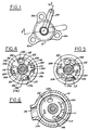
- Figure 1 is a plan view of a fuel distributing and metering assembly of the invention;
- Figure 2 is a longitudinal cross-sectional view along line 2-2 in Figure 1;
- Figure 3 is an enlarged longitudinal cross-sectional view of Figure 2;
- Figure 4 is a plan view of the rotary valve in the open position;
- Figure 5 is a plan view of the rotary valve in the closed position;
- Figure 6 is a section taken along line 6-6 in Figure 2;
- Figure 7 is a section taken along line 7-7 in Figure 2;
- Figure 8 is a section taken along lines 8-8 in Figure 2;
- Figure 9 is a section taken along lines 9-9 in Figure 2;
- Figure 10 is a schematic illustration of a fuel control system employing the fuel distributing and metering assembly shown in the above Figures; and
- Figure 11 is a graph of fuel flow versus rotary valve position for the assembly.
- With reference to Figure 10, a fuel supply system for a gas turbine engine is shown including a fuel distributing and
metering assembly 10 havingfuel injector nozzles combustor 16 of a gas turbine engine. Theassembly 10 includes aflange 10a mounted on the combustor or other casing 11 of the engine as is known. Thepilot nozzle 12 supplies relatively low fuel flow for low engine power operation while themain nozzle 14 supplies relatively high fuel flow for high engine power operation. As will become apparent hereinafter, the pilot nozzle operates initially when theassembly 10 is actuated by synchronisingring 22 and themain nozzle 14 subsequently operates in conjunction with the pilot nozzle to provide additional fuel flows to the combustor. - Although not shown, those skilled in the art will appreciate that a plurality of
assemblies 10 are disposed circumferentially around the combustor and each assembly includes and actuatedarm 24 connected to synchronisingring 22 so that all of the assemblies are actuated in unison by the ring as controlled by a suitable electrohydraulic servo control (not shown) which forms no part of this invention. - Each fuel distributing and
metering assembly 10 has asingle fuel inlet 26 connected by afuel conduit 32 to a singlecommon fuel manifold 34 supplied fuel under pressure bypump 36 andvalve 37 throughconduit 38. - With respect to the fuel distributing and metering assembly of the invention, reference is made initially to Fig. 3 where it can be seen each
assembly 10 includes anelongate valve body 40 having theflange 10a and inlet fitting 26 integrally thereon as shown. Inside thevalve body 10 is a longitudinalcylindrical chamber 42 which houses the internal valve components as now described. - Extending through a
top cap 44 sealed to the end of the valve body by o-ring 46 is a rotary valve 50 having avalve plate 52 and longitudinally extendingshaft 54 rotatable about longitudinal axis A through thechamber 42. It is apparent the upper end of theshaft 54 extends outside thecap 44 and is connected to actuatedarm 24 for rotation of theshaft 54 by movement of the synchronizing ring which is imparted to the shaft by actuatedarm 24. - An o-
ring seal 60 is disposed around theshaft 54 betweencap 44 and bushing 62 to prevent fuel leakage therepast. The lower end ofshaft 54 is guideably mounted onpin 64 also coaxial with axis A for rotation relative thereto. Between the lower and upper ends of theshaft 54 is aspring 66.Spring 66 bears upwardly against annularfixed plate 68 and downwardly against fixedannular collar 70 so as to bias thevalve plate 52 downwardly against thevalve seat 72 to effect positive metal-to-metal sealing. - As shown, the
upper portion 42a oflongitudinal chamber 42 receives fuel from inlet fitting 26. A cylindricaltubular fuel filter 74 is disposed inupper chamber 42a concentric with the longitudinal axis A to filter debris and foreign matter from the fuel prior to its enteringchamber 42a. -
Valve seat 72 is carried downstream ofvalve plate 52 on a firstcylindrical disc insert 76 and first insert is carried in turn on secondcylindrical disc insert 78 inchamber 42.Pin 64 is received in bore 65 in the first insert. As shown, thesecond insert 78 is supported axially or longitudinally on annularinner shoulder 80 of the valve body. Thefirst insert 76 includes a dependingannular flange 82 received in annular recess of the second insert. The first insert also includes acircumferential groove 84 in which an o-ring seal 86 is disposed to seal against fuel leakage between the circumference of the first insert and the wall definingcylindrical chamber 42. - Mounted upstream atop the
first insert 76 is the cylindrical disc shapedvalve seat 72. The valve seat includes a depending outer annular flange received in recess 92 in the first insert. As shown, thevalve seat 72 is stationary in the chamber while the rotary valve 50 is rotatable relative thereto. - The
valve plate 52 of rotary valve 50 includes aprimary pilot orifice 100,secondary pilot orifice 102, primarymain orifice 104 and secondary main orifice 106 (see Figure 6) extending through the longitudinal or axial thickness, i.e. from one side (outer upstream side in communication withfuel reservoir chamber 42a) of the valve plate to the other side (inner downstream side) in positive sealing contact with the inner side of the valve seat so that fuel flows through these orifices to generate four fuel flow streams, two fuel streams (primary and secondary) for eachnozzle reservoir 42a. - The
valve plate 52 also includes a groove 111 partially around the circumference to receive astop pin 113 projecting upwardly from thevalve seat 72 to control the maximum rotary motion of the valve 50. For example, Figure 4 shows the valve full open position as will be explained withupstanding stop pin 113 abutted against radial shoulder 111 a of groove 111 and Figure 5 shows the valve full closed position withstop pin 113 abutted against radial shoulder 111 b. In this way, the rotary stroke of valve 50 is controlled. - As shown best in Figure 6, the valve orifices 100-106 have different configurations to control fuel flow rate differently for each
nozzle nozzle primary pilot orifice 100 and primarymain orifice 104 are arcuate narrow slots while thesecondary pilot orifice 102 is a wider arcuate slot and the secondarymain orifice 106 is a cylindrical bore. Of course, as those skilled in the art will appreciate, the length, width and location of the orifice 100-106 can be varied to provide different fuel flows. - The
valve seat 72 includes fourorifices valve plate 52 and relative to which the valve orifices 100-106 are moved by rotation of valve 50 to meter the four fuel flow streams as the orifices 100-106 move. The valve seat orifices 110-116 are shown alone best in Figure 7 and relative to valve orifices 100-106 in Figures 4 and 5. - The seat orifices 110-116 extend through the longitudinal thickness of the
valve seat 72 into respective larger cylindrical discharge bores 120, 122, 124, 126 angularly and transversely spaced on the outer or downstream side thereof, see Figure 2 and 7 beneath the respective seat orifice. - When the valve 50 is in the closed position of Figure 5 no fuel flow passes through any of the valve orifices 100-106 or seat orifices 110-116. In full open position of Figure 4, the primary pilot fuel flow passes through
valve orifice 100,seat orifice 110 and into discharge bore 120 in the valve seat. Secondary fuel flow passes throughvalve orifice 102,seat orifice 112 and intodischarge bore 122. Primary main fuel flow passes throughvalve orifice 104,seat orifice 114 and intodischarge bore 124. Secondary main fuel flow passes throughvalve orifice 106,seat orifice 116 and intodischarge bore 126. - Referring to Figure 5, which shows the valve closed position it is clear that counterclockwise rotation of the rotary valve 50 will cause the
primary pilot orifice 100 to gradually register withprimary seat orifice 110 before any of the other orifices are registered to provide metered primary fuel to pilotnozzle 12 first. Following flow of the primary pilot fuel flow pastorifices secondary pilot orifice 102 will gradually register withprimary seat orifice 112 to provide metered secondary fuel to pilotnozzle 12 in addition to the primary fuel flow. - Upon slightly further counterclockwise rotation of the valve, the primary
main orifice 104 will gradually register with primarymain seat orifice 114 to provide metered primary fuel flow tomain nozzle 14. Still further rotation of the valve in that direction will gradually register secondarymain orifice 106 with secondarymain seat orifice 116 to provide metered secondary fuel flow in addition to primary fuel flow tomain nozzle 14 whilepilot nozzle 12 still receives its primary and secondary fuel flows. - Those skilled in the art will understand that the four fuel flows are metered to a maximum flow rate as the valve orifices 100-106 gradually register with and gradually expose seat orifices 110-116 to the fuel flow rate through the valve orifices until maximum flow rate is achieved for each fuel flow at the valve open position of Figure 4.
- The fuel flow curve versus rotary position of the valve 50 for the orifices shown in the Figures is illustrated in Figure 11. Flow is plotted in PPH (pints/hour: equivalent to pints x 0.5638 litres/hour.
- As mentioned, downstream discharge bores 120-126 are aligned beneath their respective seat orifices 110-116 to receive fuel flow therefrom Figure 7. Aligned beneath discharge bores 120-126 in an angularly and transversely spaced array are cylindrical angular spaced discharge bores 130, 132, 134, 136 in the first insert, e.g. see Figure 3, 4 and 8.
First insert 76 includescylindrical plugs plug upper end respective discharge plug cylindrical discharge passages 137b, 138b in the plugs.Passages 137b, 138b in turn communicate with the openupper ends 150a, 154a of primaryfuel discharge tubes plug - As shown best in Figure 3, the downstream end of each
plug fuel tubes - The secondary pilot and main fuel discharge bores 132, 136 extend through the axial thickness of the
first insert 76 to the downstream side thereof without any plugs therein, Figure 8. - As will be explained later, primary pilot and primary main fuel flow through the inner downstream discharge passages in
tubes strut portion 10b of the valve body to the pilot andmain nozzles - On the other hand, secondary pilot and main fuel flow discharges from discharge bores 132, 136 in the
first insert 76 intotransverse discharge slots second insert 78, see Fig. 9.Transverse slots insert 78 and include a radially definedportion 160a, 162a whose center axis is substantially coaxial with that of the respective discharge bore 132, 136 in the upstreamfirst insert 76. Theslots rectilinear portion 160b, 162b extending transversely from the radial portion to downstream discharge bores 170, 172 in the upstream side of the second insert through whichtubes - Disposed in each downstream discharge bore 170, 172 are
plugs transverse slots plugs cylindrical passages tubes downstream discharge passages 180b, 182b aroundtubes transverse slots - Each
plug main fuel tubes annular passages 180b, 182b is received in therespective tube tubes main nozzle - As shown best in Figures 2 and 9, the
downstream discharge passage 180b andtube 150 for primary and secondary pilot fuel forpilot nozzle 12 are nested longitudinally one inside the other and are in communication with longitudinally nestedtubes tube 154 for primary and secondary main fuel formain nozzle 14 are nested longitudinally one inside the other and are in communication with longitudinally nestedtubes plugs - Each
plug ring - As shown in Figure 2, longitudinally nested
tubes strut portion 10b torespective fuel nozzles
Claims (20)
Applications Claiming Priority (2)
| Application Number | Priority Date | Filing Date | Title |
|---|---|---|---|
| US06/926,492 US4742685A (en) | 1986-11-04 | 1986-11-04 | Fuel distributing and metering assembly |
| US926492 | 1986-11-04 |
Publications (3)
| Publication Number | Publication Date |
|---|---|
| EP0266953A2 EP0266953A2 (en) | 1988-05-11 |
| EP0266953A3 EP0266953A3 (en) | 1988-08-03 |
| EP0266953B1 true EP0266953B1 (en) | 1990-02-28 |
Family
ID=25453283
Family Applications (1)
| Application Number | Title | Priority Date | Filing Date |
|---|---|---|---|
| EP87309487A Expired EP0266953B1 (en) | 1986-11-04 | 1987-10-27 | Fuel distributing and metering assembly |
Country Status (2)
| Country | Link |
|---|---|
| US (1) | US4742685A (en) |
| EP (1) | EP0266953B1 (en) |
Families Citing this family (12)
| Publication number | Priority date | Publication date | Assignee | Title |
|---|---|---|---|---|
| US5003771A (en) * | 1988-10-13 | 1991-04-02 | United Technologies Corporation | Fuel distribution valve for a combustion chamber |
| US4938418A (en) * | 1988-12-01 | 1990-07-03 | Fuel Systems Textron Inc. | Modular fuel nozzle assembly for gas turbine engines |
| US4941447A (en) * | 1989-02-21 | 1990-07-17 | Colt Industries Inc. | Metering valve |
| US6141968A (en) * | 1997-10-29 | 2000-11-07 | Pratt & Whitney Canada Corp. | Fuel nozzle for gas turbine engine with slotted fuel conduits and cover |
| US6755024B1 (en) * | 2001-08-23 | 2004-06-29 | Delavan Inc. | Multiplex injector |
| GB0605432D0 (en) | 2006-03-17 | 2006-04-26 | Rolls Royce Plc | Component for fuel supply |
| KR100820233B1 (en) * | 2006-10-31 | 2008-04-08 | 한국전력공사 | Combustor, multi combustor including same, and combustion method |
| FR2922995B1 (en) * | 2007-10-31 | 2009-12-04 | Snecma | ANNULAR COMBUSTION CHAMBER FOR A GAS TURBINE ENGINE. |
| US7992390B2 (en) * | 2008-09-23 | 2011-08-09 | Pratt & Whitney Canada Corp. | External rigid fuel manifold |
| US8844500B2 (en) * | 2011-01-22 | 2014-09-30 | Cummins Intellectual Property, Inc. | Enclosure for high pressure fuel rail |
| GB2516445A (en) * | 2013-07-22 | 2015-01-28 | Rolls Royce Plc | A fuel spray nozzle |
| US11434775B2 (en) | 2020-08-31 | 2022-09-06 | Rolls-Royce North American Technologies Inc. | Turbine engine with metered cooling system |
Family Cites Families (13)
| Publication number | Priority date | Publication date | Assignee | Title |
|---|---|---|---|---|
| US1033015A (en) * | 1911-02-25 | 1912-07-16 | Erhard Junghans | Gas-turbine and the like. |
| US2508420A (en) * | 1948-09-21 | 1950-05-23 | Westinghouse Electric Corp | Combustion apparatus |
| US2806519A (en) * | 1949-06-17 | 1957-09-17 | Rolls Royce | Fuel-systems for internal combustion engines with means to compensate for an operating variable |
| US2993338A (en) * | 1958-04-09 | 1961-07-25 | Gen Motors Corp | Fuel spray bar assembly |
| US3335567A (en) * | 1965-11-19 | 1967-08-15 | Gen Electric | Multi-nozzle fuel delivery system |
| US3625252A (en) * | 1968-04-23 | 1971-12-07 | Corning Glass Works | Linearly variable linear fluidic resistor |
| US3516252A (en) * | 1969-02-26 | 1970-06-23 | United Aircraft Corp | Fuel manifold system |
| US3698186A (en) * | 1970-12-24 | 1972-10-17 | United Aircraft Corp | Afterburner combustion apparatus |
| US3793838A (en) * | 1972-09-05 | 1974-02-26 | Gen Electric | Augmenter fuel injection mounting system |
| US3949775A (en) * | 1974-07-12 | 1976-04-13 | General Electric Company | Fuel supply and distribution system |
| GB2036296B (en) * | 1978-11-20 | 1982-12-01 | Rolls Royce | Gas turbine |
| US4312185A (en) * | 1980-02-19 | 1982-01-26 | General Electric Company | Low profile fuel injection system |
| GB2158570B (en) * | 1984-05-10 | 1988-11-30 | Ex Cell O Corp | Mechanically operated fuel control system |
-
1986
- 1986-11-04 US US06/926,492 patent/US4742685A/en not_active Expired - Lifetime
-
1987
- 1987-10-27 EP EP87309487A patent/EP0266953B1/en not_active Expired
Also Published As
| Publication number | Publication date |
|---|---|
| EP0266953A3 (en) | 1988-08-03 |
| US4742685A (en) | 1988-05-10 |
| EP0266953A2 (en) | 1988-05-11 |
Similar Documents
| Publication | Publication Date | Title |
|---|---|---|
| US4742685A (en) | Fuel distributing and metering assembly | |
| US5636980A (en) | Burner apparatus | |
| US6250063B1 (en) | Fuel staging apparatus and methods for gas turbine nozzles | |
| EP1069377B1 (en) | Fuel purging fuel injector | |
| US5881550A (en) | Staged fuel injection system with shuttle valve and fuel injector therefor | |
| US3939871A (en) | Burner block assembly | |
| US4021190A (en) | Burner block valve assembly | |
| US5605287A (en) | Airblast fuel nozzle with swirl slot metering valve | |
| US4938418A (en) | Modular fuel nozzle assembly for gas turbine engines | |
| JP2007517181A (en) | Helical passage fuel distributor and method | |
| CN103765099A (en) | Staged cooling flow nozzle valve | |
| EP0150619B1 (en) | Flow dividing valve | |
| US4590768A (en) | Fuel distribution valve flow trimming and locking means | |
| US20080000538A1 (en) | Multi-Channel, Multi-Phase Flow Metering Valve | |
| WO1998041796A1 (en) | Valve | |
| US7913973B1 (en) | Reverse flow fueldraulic valve | |
| GB2158570A (en) | Mechanically operated fuel control system | |
| CN110529879A (en) | Two-phase fuel nozzle | |
| US2796296A (en) | Nozzle exit valve | |
| US5941074A (en) | Multi-port proportional fuel control valve for gas turbine engine | |
| US2701609A (en) | Fuel distributing apparatus for power plants | |
| US4399943A (en) | Fluid injector | |
| US5694967A (en) | Multi-port proportional flow control valve | |
| JP2017223225A (en) | Liquid fuel control valve for gas turbine engine and method for controlling flow of liquid fuel to engine | |
| US5392994A (en) | Fuel injection nozzle |
Legal Events
| Date | Code | Title | Description |
|---|---|---|---|
| PUAI | Public reference made under article 153(3) epc to a published international application that has entered the european phase |
Free format text: ORIGINAL CODE: 0009012 |
|
| AK | Designated contracting states |
Kind code of ref document: A2 Designated state(s): FR GB |
|
| PUAL | Search report despatched |
Free format text: ORIGINAL CODE: 0009013 |
|
| AK | Designated contracting states |
Kind code of ref document: A3 Designated state(s): FR GB |
|
| 17P | Request for examination filed |
Effective date: 19880909 |
|
| 17Q | First examination report despatched |
Effective date: 19881107 |
|
| GRAA | (expected) grant |
Free format text: ORIGINAL CODE: 0009210 |
|
| AK | Designated contracting states |
Kind code of ref document: B1 Designated state(s): FR GB |
|
| ET | Fr: translation filed | ||
| PLBE | No opposition filed within time limit |
Free format text: ORIGINAL CODE: 0009261 |
|
| STAA | Information on the status of an ep patent application or granted ep patent |
Free format text: STATUS: NO OPPOSITION FILED WITHIN TIME LIMIT |
|
| 26N | No opposition filed | ||
| PGFP | Annual fee paid to national office [announced via postgrant information from national office to epo] |
Ref country code: GB Payment date: 19910926 Year of fee payment: 5 |
|
| PGFP | Annual fee paid to national office [announced via postgrant information from national office to epo] |
Ref country code: FR Payment date: 19911021 Year of fee payment: 5 |
|
| PG25 | Lapsed in a contracting state [announced via postgrant information from national office to epo] |
Ref country code: GB Effective date: 19921027 |
|
| GBPC | Gb: european patent ceased through non-payment of renewal fee |
Effective date: 19921027 |
|
| PG25 | Lapsed in a contracting state [announced via postgrant information from national office to epo] |
Ref country code: FR Effective date: 19930630 |
|
| REG | Reference to a national code |
Ref country code: FR Ref legal event code: ST |