EP0263045A1 - Case comprising a thermally formed container with a hinged cover - Google Patents
Case comprising a thermally formed container with a hinged cover Download PDFInfo
- Publication number
- EP0263045A1 EP0263045A1 EP87420262A EP87420262A EP0263045A1 EP 0263045 A1 EP0263045 A1 EP 0263045A1 EP 87420262 A EP87420262 A EP 87420262A EP 87420262 A EP87420262 A EP 87420262A EP 0263045 A1 EP0263045 A1 EP 0263045A1
- Authority
- EP
- European Patent Office
- Prior art keywords
- housing
- case
- box
- cover
- bosses
- Prior art date
- Legal status (The legal status is an assumption and is not a legal conclusion. Google has not performed a legal analysis and makes no representation as to the accuracy of the status listed.)
- Granted
Links
- 230000005489 elastic deformation Effects 0.000 claims description 2
- 239000010437 gem Substances 0.000 claims 1
- 229910001751 gemstone Inorganic materials 0.000 claims 1
- 238000003856 thermoforming Methods 0.000 description 2
- 240000008042 Zea mays Species 0.000 description 1
- 210000004027 cell Anatomy 0.000 description 1
- 238000009434 installation Methods 0.000 description 1
- 238000003466 welding Methods 0.000 description 1
Images

Classifications
-
- B—PERFORMING OPERATIONS; TRANSPORTING
- B65—CONVEYING; PACKING; STORING; HANDLING THIN OR FILAMENTARY MATERIAL
- B65D—CONTAINERS FOR STORAGE OR TRANSPORT OF ARTICLES OR MATERIALS, e.g. BAGS, BARRELS, BOTTLES, BOXES, CANS, CARTONS, CRATES, DRUMS, JARS, TANKS, HOPPERS, FORWARDING CONTAINERS; ACCESSORIES, CLOSURES, OR FITTINGS THEREFOR; PACKAGING ELEMENTS; PACKAGES
- B65D43/00—Lids or covers for rigid or semi-rigid containers
- B65D43/14—Non-removable lids or covers
- B65D43/16—Non-removable lids or covers hinged for upward or downward movement
- B65D43/163—Non-removable lids or covers hinged for upward or downward movement the container and the lid being made separately
- B65D43/164—Non-removable lids or covers hinged for upward or downward movement the container and the lid being made separately and connected by interfitting hinge elements integrally with the container and the lid formed respectively
Definitions
- the present invention relates to cases or other cases in which the cover is articulated laterally on the sides of a case obtained by the assembly of a thermoformed bottom and a lower back.
- the lateral articulation bosses are provided on projecting lugs integral with the housing and folded against the side walls of the latter during assembly of the cover.
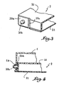
- the case shown in fig. 1 essentially comprises a cover 1, the rear part of which is articulated laterally on a housing 2, which is in the known manner made by assembling (bonding or welding) a thermoformed bottom 20 and a lower back 21.
- thermoformed bottom 20 has on each of its side walls a protruding tab 20 a which, during the thermoforming operation, has been stamped to present a boss 20 b which projects downwards.
- the two tabs 20 a do not in any way interfere with the assembly of the parts 20 and 21, an assembly which in the usual manner determines an overflowing pad which is intended to serve as a stop for the free edge of the cover 1.
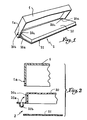
- the lower back, referenced 23 which laterally comprises two projecting legs 23 a , each of which is provided with a boss 23 b turned downwards in the manner shown in FIG. 5.
- the two legs 23 a are folded vertically against the side walls of the bottom 22 (these walls advantageously having depressions 22 a to receive these legs), so that the bosses 23 b , then turned laterally, are capable of being introduced into the perforations 1 a of the cover 1.
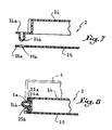
- Fig. 7 and 8 illustrate a third embodiment of the invention, according to which the protruding legs, referenced 24 a and provided with a boss 24 b facing downwards, are integral with the thermoformed bottom 24, as in the case of fig. 2 to 4.
- the back 25 has two equivalent overhanging legs 25 a which are perforated at 25 b and which, after introduction of the bosses 24 b into the perforations 25 b , are joined to the legs 24 a when the back 25 is welded against the bottom 24.
- the double legs 24 a -25 a thus obtained can be folded up as illustrated in fig. 8, so that the bosses 24 b are engaged in the perforations 1 a of the cover 1 to ensure the articulated mounting of the latter on the housing.
Abstract
Description
La présente invention a trait aux écrins ou autres étuis dans lesquels le couvercle s'articule latéralement sur les côtés d'un boîtier obtenu par l'assemblage d'un fond thermoformé et d'un dos inférieur.The present invention relates to cases or other cases in which the cover is articulated laterally on the sides of a case obtained by the assembly of a thermoformed bottom and a lower back.
On sait que dans les écrins de ce genre, le montage articulé du couvercle sur le boîtier est généralement assuré à l'aide de deux rivets ou organes similaires qui sont introduits dans des perforations pratiquées en coïncidence dans les parois latérales du boîtier et du couvercle. On comprend que la pose de ces rivets constitue une opération supplémentaire qui grève de manière non négligeable le prix de revient des articles finis.We know that in cases of this kind, the hinged mounting of the cover on the housing is generally ensured by means of two rivets or similar members which are introduced into perforations formed coincidentally in the side walls of the housing and of the cover. It is understood that the installation of these rivets constitutes an additional operation which significantly increases the cost price of the finished articles.
Aussi a-t-on proposé d'assurer l'articulation du couvercle moyennant encliquetage élastique de bossages latéraux prévus en saillie sur le fond thermoformé, à l'intérieur de perforations ménagées dans les côtés du couvercle. Le montage est quelque peu simplifié, mais il n'en reste pas moins que la réalisation des bossages latéraux implique le plus souvent une reprise des boîtiers après thermoformage, de sorte que le coût reste élevé.It has therefore been proposed to ensure the articulation of the cover by means of elastic snap-fastening of lateral bosses provided projecting from the thermoformed bottom, inside perforations made in the sides of the cover. The assembly is somewhat simplified, but the fact remains that the realization of the lateral bosses generally involves a resumption of the boxes after thermoforming, so that the cost remains high.
C'est à ces inconvénients que la présente invention entend remédier.It is these drawbacks that the present invention intends to remedy.
Suivant l'invention, les bossages latéraux d'articulation sont prévus sur des pattes débordantes solidaires du boîtier et rabattues contre les parois latérales de celui-ci lors du montage du couvercle.According to the invention, the lateral articulation bosses are provided on projecting lugs integral with the housing and folded against the side walls of the latter during assembly of the cover.
Le dessin annexé, donné à titre d'exemple, permettra de mieux comprendre l'invention, les caractéristiques qu'elle présente et les avantages qu'elle est susceptible de procurer :
- Fig. 1 est une vue en perspective d'un écrin établi conformément à l'invention.
- Fig. 2 et 3 et 4 illustrent à échelle très agrandie le mode de réalisation de cet écrin.
- Fig. 5 et 6, respectivement 7 et 8, sont des coupes analogues à celles de fig. 2 et 4, mais correspondant à deux variantes de mise en oeuvre de l'invention.
- Fig. 1 is a perspective view of a case established in accordance with the invention.
- Fig. 2 and 3 and 4 illustrate on a very enlarged scale the embodiment of this case.
- Fig. 5 and 6, respectively 7 and 8, are sections similar to those of FIG. 2 and 4, but corresponding to two variant embodiments of the invention.
L'écrin représenté en fig. 1 comprend essentiellement un couvercle 1 dont la partie arrière s'articule latéralement sur un boîtier 2, lequel est à la façon en soi connue réalisé par assemblage (collage ou soudage) d'un fond thermoformé 20 et d'un dos inférieur 21.The case shown in fig. 1 essentially comprises a
Comme montré en fig. 2, le fond thermoformé 20 comporte sur chacune de ses parois latérales une patte débordante 20 a qui, lors de l'opération de thermoformage, a été emboutie pour présenter un bossage 20 b qui fait saillie vers le bas. Les deux pattes 20 a ne gênent en aucune manière l'assemblage des pièces 20 et 21, assemblage qui détermine à la façon usuelle un patin débordant qui est destiné à servir de butée pour le bord libre du couvercle 1.As shown in fig. 2, the
Lors du montage de ce couvercle 1, il suffit à l'opérateur de relever les deux pattes 20 a et d'introduire, moyennant une déformation élastique momentanée, les bossages 20 b dans des perforations 1 a pratiquées dans les parois latérales du couvercle 1. On obtient de la sorte le montage articulé représenté en fig. 4.When mounting this
On observera que si l'on prend soin de prévoir sur chaque paroi latérale du fond 20, au niveau de la patte débordante 20 a, une partie en dépression telle que celle référencée 20 c, le repliage vers le haut des pattes 20 a ne détermine aucune surépaisseur sur les côtés du fond 20.It will be observed that if care is taken to provide on each side wall of the
Dans la variante de mise en oeuvre illustrée en fig. 5 et 6, c'est le dos inférieur, référencé 23, qui comporte latéralement deux pattes débordantes 23 a dont chacune est pourvue d'un bossage 23 b tourné vers le bas à la manière représentée en fig. 5. Ici également, après assemblage du fond 22 et du dos 23, les deux pattes 23 a sont repliées à la verticale contre les parois latérales du fond 22 (ces parois présentant avantageusement des dépressions 22 a pour recevoir ces pattes), de sorte que les bossages 23 b, alors tournés latéralement, sont susceptibles d'être introduits dans les perforations 1 a du couvercle 1.In the variant of implementation illustrated in FIG. 5 and 6, it is the lower back, referenced 23, which laterally comprises two
Fig. 7 et 8 illustrent un troisième mode de mise en oeuvre de l'invention, suivant lequel les pattes débordantes, référencées 24 a et pourvues d'un bossage 24 b tourné vers le bas, sont solidaires du fond thermoformé 24, comme dans le cas de fig. 2 à 4. Toutefois, le dos 25 comporte deux pattes débordantes 25 a équivalentes qui sont perforées en 25 b et qui, après introduction des bossages 24 b dans les perforations 25 b, sont assemblées aux pattes 24 a lors du soudage du dos 25 contre le fond 24. Les pattes doubles 24 a-25 a ainsi obtenues peuvent être rabattues vers le haut comme illustré en fig. 8, afin que les bossages 24 b soient engagés dans les perforations 1 a du couvercle 1 pour assurer le montage articulé de celui-ci sur le boîtier.Fig. 7 and 8 illustrate a third embodiment of the invention, according to which the protruding legs, referenced 24 a and provided with a boss 24 b facing downwards, are integral with the
On notera que le doublage ainsi réalisé est susceptible d'être adopté dans le cas du mode de mise en oeuvre suivant fig. 5 et 6, le bord libre du fond 22 étant pourvu à cet effet de pattes débordantes 22 b qui ferment les bossages 23 b des pattes 23 a du dos 23.It will be noted that the doubling thus produced is likely to be adopted in the case of the mode of implementation according to FIG. 5 and 6, the free edge of the
Dans tous les cas, le mode d'articulation obtenu est particulièrement robuste et sûr, tout au long de l'utilisation de l'écrin.In all cases, the mode of articulation obtained is particularly robust and safe, throughout the use of the case.
Claims (4)
Priority Applications (1)
| Application Number | Priority Date | Filing Date | Title |
|---|---|---|---|
| AT87420262T ATE56677T1 (en) | 1986-10-01 | 1987-09-30 | BOX CONSISTING OF A HEAT MOLDED CONTAINER WITH A HINGED LID. |
Applications Claiming Priority (2)
| Application Number | Priority Date | Filing Date | Title |
|---|---|---|---|
| FR8613905A FR2604979B1 (en) | 1986-10-01 | 1986-10-01 | IMPROVEMENTS IN BOXES OF THE TYPE WITH THERMOFORMED HOUSING AND ARTICULATED LID |
| FR8613905 | 1986-10-01 |
Publications (2)
| Publication Number | Publication Date |
|---|---|
| EP0263045A1 true EP0263045A1 (en) | 1988-04-06 |
| EP0263045B1 EP0263045B1 (en) | 1990-09-19 |
Family
ID=9339589
Family Applications (1)
| Application Number | Title | Priority Date | Filing Date |
|---|---|---|---|
| EP87420262A Expired - Lifetime EP0263045B1 (en) | 1986-10-01 | 1987-09-30 | Case comprising a thermally formed container with a hinged cover |
Country Status (7)
| Country | Link |
|---|---|
| US (1) | US4819828A (en) |
| EP (1) | EP0263045B1 (en) |
| AT (1) | ATE56677T1 (en) |
| CA (1) | CA1316467C (en) |
| DE (1) | DE3765073D1 (en) |
| ES (1) | ES2017521B3 (en) |
| FR (1) | FR2604979B1 (en) |
Families Citing this family (7)
| Publication number | Priority date | Publication date | Assignee | Title |
|---|---|---|---|---|
| US5076455A (en) * | 1991-04-15 | 1991-12-31 | Coopoer Industries, Inc. | Integral hinge for electrical equipment enclosures |
| US10817768B1 (en) | 2019-12-20 | 2020-10-27 | Capital One Services, Llc | Systems and methods for preventing chip fraud by inserts in chip pocket |
| US10977539B1 (en) | 2019-12-20 | 2021-04-13 | Capital One Services, Llc | Systems and methods for use of capacitive member to prevent chip fraud |
| US10810475B1 (en) | 2019-12-20 | 2020-10-20 | Capital One Services, Llc | Systems and methods for overmolding a card to prevent chip fraud |
| US10888940B1 (en) | 2019-12-20 | 2021-01-12 | Capital One Services, Llc | Systems and methods for saw tooth milling to prevent chip fraud |
| US11049822B1 (en) | 2019-12-20 | 2021-06-29 | Capital One Services, Llc | Systems and methods for the use of fraud prevention fluid to prevent chip fraud |
| US11715103B2 (en) | 2020-08-12 | 2023-08-01 | Capital One Services, Llc | Systems and methods for chip-based identity verification and transaction authentication |
Citations (5)
| Publication number | Priority date | Publication date | Assignee | Title |
|---|---|---|---|---|
| US3015383A (en) * | 1960-08-30 | 1962-01-02 | Shiffman Jerome | Display containers |
| US3841528A (en) * | 1971-09-29 | 1974-10-15 | H Eisenberg | Container for liquids having hinged lid allowing easy stacking |
| US3977744A (en) * | 1975-02-03 | 1976-08-31 | Dewitt F Carlos | Posse box report clip board |
| DE3204101A1 (en) * | 1981-02-07 | 1982-09-23 | Olympus Optical Co., Ltd., Tokyo | STORAGE BOX FOR MAGNETIC TAPE CASSETTES |
| DE3145203A1 (en) * | 1981-11-13 | 1983-05-26 | Walter 7292 Baiersbronn Braun | Cassette for receiving elongate articles |
Family Cites Families (4)
| Publication number | Priority date | Publication date | Assignee | Title |
|---|---|---|---|---|
| US2765949A (en) * | 1953-10-23 | 1956-10-09 | Hillman Swan | Container |
| US3984028A (en) * | 1976-01-26 | 1976-10-05 | Eli Lilly And Company | Container hinge construction |
| US4209090A (en) * | 1979-03-27 | 1980-06-24 | Klein Herbert S | Display package |
| US4211337A (en) * | 1979-06-08 | 1980-07-08 | Minnesota Mining And Manufacturing Company | Multiple-point hinge for double-wall plastic box |
-
1986
- 1986-10-01 FR FR8613905A patent/FR2604979B1/en not_active Expired
-
1987
- 1987-09-25 US US07/101,197 patent/US4819828A/en not_active Expired - Fee Related
- 1987-09-29 CA CA000548161A patent/CA1316467C/en not_active Expired - Fee Related
- 1987-09-30 DE DE8787420262T patent/DE3765073D1/en not_active Expired - Lifetime
- 1987-09-30 EP EP87420262A patent/EP0263045B1/en not_active Expired - Lifetime
- 1987-09-30 ES ES87420262T patent/ES2017521B3/en not_active Expired - Lifetime
- 1987-09-30 AT AT87420262T patent/ATE56677T1/en active
Patent Citations (5)
| Publication number | Priority date | Publication date | Assignee | Title |
|---|---|---|---|---|
| US3015383A (en) * | 1960-08-30 | 1962-01-02 | Shiffman Jerome | Display containers |
| US3841528A (en) * | 1971-09-29 | 1974-10-15 | H Eisenberg | Container for liquids having hinged lid allowing easy stacking |
| US3977744A (en) * | 1975-02-03 | 1976-08-31 | Dewitt F Carlos | Posse box report clip board |
| DE3204101A1 (en) * | 1981-02-07 | 1982-09-23 | Olympus Optical Co., Ltd., Tokyo | STORAGE BOX FOR MAGNETIC TAPE CASSETTES |
| DE3145203A1 (en) * | 1981-11-13 | 1983-05-26 | Walter 7292 Baiersbronn Braun | Cassette for receiving elongate articles |
Also Published As
| Publication number | Publication date |
|---|---|
| ES2017521B3 (en) | 1991-02-16 |
| US4819828A (en) | 1989-04-11 |
| EP0263045B1 (en) | 1990-09-19 |
| FR2604979B1 (en) | 1988-12-09 |
| FR2604979A1 (en) | 1988-04-15 |
| CA1316467C (en) | 1993-04-20 |
| DE3765073D1 (en) | 1990-10-25 |
| ATE56677T1 (en) | 1990-10-15 |
Similar Documents
| Publication | Publication Date | Title |
|---|---|---|
| EP0263045B1 (en) | Case comprising a thermally formed container with a hinged cover | |
| FR2766160A1 (en) | PACKAGING BOX HAVING A CROWN | |
| FR2577782A1 (en) | CONTAINER FOR RECEIVING COVERS AND DISHES FOR SERVICE ON BOARD | |
| EP1174348B1 (en) | Cardboard box and closure device | |
| EP0404688A1 (en) | Removable water tank for domestic appliance and domestic appliance provided with such tank | |
| FR2773190A1 (en) | EXTERIOR DOOR HANDLE ASSEMBLY | |
| EP0935562B1 (en) | Packaging box comprising a cardboard bottom and a transparent lid | |
| FR2710791A1 (en) | Waterproof case for electrical equipment. | |
| EP0117812B1 (en) | Gasket for avionics tray | |
| EP0721857B1 (en) | Device for storing objects, in particular in motor vehicles | |
| FR2720557A1 (en) | Box especially for low voltage electrical equipment. | |
| FR2675778A1 (en) | Device for fixing a lid on a packaging box made of plastic material | |
| EP0802599A1 (en) | Floor outlet for electrical apparatus | |
| FR2530525A1 (en) | CASSETTE FOR RECEIVING TOOLS | |
| FR2789882A1 (en) | HOUSEHOLD APPLIANCE WITH A BASE PROTECTION BAND | |
| EP0027091A1 (en) | Display case | |
| FR2553384A1 (en) | Tray with plastic cover | |
| FR2802897A1 (en) | Cigarette pack is easier to open than prior art and provides easier access to the contents | |
| EP0571293B1 (en) | Polygonal box from sheet material and blank for the manufacture of such a box | |
| FR2701346A1 (en) | Device for inserting and extracting pluggable electronic assemblies | |
| FR2718716A1 (en) | Semi=rigid packaging for bottles | |
| FR1464370A (en) | Jewelry box with protrusions on the inner edges of its two valves for retaining the lining | |
| FR2627167A1 (en) | Cheese packaging box - has polygonal semi rigid base with locating bosses for lid and built in ventilation passage ways | |
| FR2696154A1 (en) | Cardboard box with integral cover - is formed from cardboard blank which is cut-out such that when folded and assemble,it forms parallepiped, with cover formed from cut-out second sheet which slides into slots in first sheet | |
| FR2663908A1 (en) | Support case |
Legal Events
| Date | Code | Title | Description |
|---|---|---|---|
| PUAI | Public reference made under article 153(3) epc to a published international application that has entered the european phase |
Free format text: ORIGINAL CODE: 0009012 |
|
| AK | Designated contracting states |
Kind code of ref document: A1 Designated state(s): AT BE CH DE ES GB GR IT LI LU NL SE |
|
| 17P | Request for examination filed |
Effective date: 19880624 |
|
| 17Q | First examination report despatched |
Effective date: 19900112 |
|
| GRAA | (expected) grant |
Free format text: ORIGINAL CODE: 0009210 |
|
| AK | Designated contracting states |
Kind code of ref document: B1 Designated state(s): AT BE CH DE ES GB GR IT LI LU NL SE |
|
| PG25 | Lapsed in a contracting state [announced via postgrant information from national office to epo] |
Ref country code: SE Effective date: 19900919 Ref country code: NL Effective date: 19900919 Ref country code: GR Free format text: LAPSE BECAUSE OF FAILURE TO SUBMIT A TRANSLATION OF THE DESCRIPTION OR TO PAY THE FEE WITHIN THE PRESCRIBED TIME-LIMIT Effective date: 19900919 Ref country code: AT Effective date: 19900919 |
|
| REF | Corresponds to: |
Ref document number: 56677 Country of ref document: AT Date of ref document: 19901015 Kind code of ref document: T |
|
| PG25 | Lapsed in a contracting state [announced via postgrant information from national office to epo] |
Ref country code: LU Free format text: LAPSE BECAUSE OF NON-PAYMENT OF DUE FEES Effective date: 19900930 |
|
| ITF | It: translation for a ep patent filed |
Owner name: ING. BETTELLO LUIGI |
|
| REF | Corresponds to: |
Ref document number: 3765073 Country of ref document: DE Date of ref document: 19901025 |
|
| GBT | Gb: translation of ep patent filed (gb section 77(6)(a)/1977) | ||
| NLV1 | Nl: lapsed or annulled due to failure to fulfill the requirements of art. 29p and 29m of the patents act | ||
| PLBE | No opposition filed within time limit |
Free format text: ORIGINAL CODE: 0009261 |
|
| STAA | Information on the status of an ep patent application or granted ep patent |
Free format text: STATUS: NO OPPOSITION FILED WITHIN TIME LIMIT |
|
| 26N | No opposition filed | ||
| ITTA | It: last paid annual fee | ||
| PGFP | Annual fee paid to national office [announced via postgrant information from national office to epo] |
Ref country code: ES Payment date: 19910930 Year of fee payment: 5 |
|
| PGFP | Annual fee paid to national office [announced via postgrant information from national office to epo] |
Ref country code: BE Payment date: 19911022 Year of fee payment: 5 |
|
| PGFP | Annual fee paid to national office [announced via postgrant information from national office to epo] |
Ref country code: CH Payment date: 19911127 Year of fee payment: 5 |
|
| PGFP | Annual fee paid to national office [announced via postgrant information from national office to epo] |
Ref country code: GB Payment date: 19920922 Year of fee payment: 6 Ref country code: DE Payment date: 19920922 Year of fee payment: 6 |
|
| PG25 | Lapsed in a contracting state [announced via postgrant information from national office to epo] |
Ref country code: LI Effective date: 19920930 Ref country code: CH Effective date: 19920930 Ref country code: BE Effective date: 19920930 |
|
| PG25 | Lapsed in a contracting state [announced via postgrant information from national office to epo] |
Ref country code: ES Free format text: LAPSE BECAUSE OF EXPIRATION OF PROTECTION Effective date: 19921001 |
|
| BERE | Be: lapsed |
Owner name: S.A. VINCENT-JOURET Effective date: 19920930 |
|
| REG | Reference to a national code |
Ref country code: CH Ref legal event code: PL |
|
| PG25 | Lapsed in a contracting state [announced via postgrant information from national office to epo] |
Ref country code: GB Effective date: 19930930 |
|
| GBPC | Gb: european patent ceased through non-payment of renewal fee |
Effective date: 19930930 |
|
| PG25 | Lapsed in a contracting state [announced via postgrant information from national office to epo] |
Ref country code: DE Effective date: 19940601 |
|
| REG | Reference to a national code |
Ref country code: ES Ref legal event code: FD2A Effective date: 19990601 |
|
| PG25 | Lapsed in a contracting state [announced via postgrant information from national office to epo] |
Ref country code: IT Free format text: LAPSE BECAUSE OF NON-PAYMENT OF DUE FEES;WARNING: LAPSES OF ITALIAN PATENTS WITH EFFECTIVE DATE BEFORE 2007 MAY HAVE OCCURRED AT ANY TIME BEFORE 2007. THE CORRECT EFFECTIVE DATE MAY BE DIFFERENT FROM THE ONE RECORDED. Effective date: 20050930 |