EP0260701B1 - Method of and apparatus for making cartridge shell plate for films - Google Patents
Method of and apparatus for making cartridge shell plate for films Download PDFInfo
- Publication number
- EP0260701B1 EP0260701B1 EP19870113645 EP87113645A EP0260701B1 EP 0260701 B1 EP0260701 B1 EP 0260701B1 EP 19870113645 EP19870113645 EP 19870113645 EP 87113645 A EP87113645 A EP 87113645A EP 0260701 B1 EP0260701 B1 EP 0260701B1
- Authority
- EP
- European Patent Office
- Prior art keywords
- thin
- thin sheets
- sheets
- station
- velvet
- Prior art date
- Legal status (The legal status is an assumption and is not a legal conclusion. Google has not performed a legal analysis and makes no representation as to the accuracy of the status listed.)
- Expired - Lifetime
Links
Images


Classifications
-
- B—PERFORMING OPERATIONS; TRANSPORTING
- B21—MECHANICAL METAL-WORKING WITHOUT ESSENTIALLY REMOVING MATERIAL; PUNCHING METAL
- B21D—WORKING OR PROCESSING OF SHEET METAL OR METAL TUBES, RODS OR PROFILES WITHOUT ESSENTIALLY REMOVING MATERIAL; PUNCHING METAL
- B21D51/00—Making hollow objects
- B21D51/16—Making hollow objects characterised by the use of the objects
- B21D51/26—Making hollow objects characterised by the use of the objects cans or tins; Closing same in a permanent manner
- B21D51/2676—Cans or tins having longitudinal or helical seams
-
- B—PERFORMING OPERATIONS; TRANSPORTING
- B26—HAND CUTTING TOOLS; CUTTING; SEVERING
- B26D—CUTTING; DETAILS COMMON TO MACHINES FOR PERFORATING, PUNCHING, CUTTING-OUT, STAMPING-OUT OR SEVERING
- B26D1/00—Cutting through work characterised by the nature or movement of the cutting member or particular materials not otherwise provided for; Apparatus or machines therefor; Cutting members therefor
- B26D1/56—Cutting through work characterised by the nature or movement of the cutting member or particular materials not otherwise provided for; Apparatus or machines therefor; Cutting members therefor involving a cutting member which travels with the work otherwise than in the direction of the cut, i.e. flying cutter
- B26D1/60—Cutting through work characterised by the nature or movement of the cutting member or particular materials not otherwise provided for; Apparatus or machines therefor; Cutting members therefor involving a cutting member which travels with the work otherwise than in the direction of the cut, i.e. flying cutter and is mounted on a movable carriage
- B26D1/605—Cutting through work characterised by the nature or movement of the cutting member or particular materials not otherwise provided for; Apparatus or machines therefor; Cutting members therefor involving a cutting member which travels with the work otherwise than in the direction of the cut, i.e. flying cutter and is mounted on a movable carriage for thin material, e.g. for sheets, strips or the like
-
- B—PERFORMING OPERATIONS; TRANSPORTING
- B26—HAND CUTTING TOOLS; CUTTING; SEVERING
- B26D—CUTTING; DETAILS COMMON TO MACHINES FOR PERFORATING, PUNCHING, CUTTING-OUT, STAMPING-OUT OR SEVERING
- B26D5/00—Arrangements for operating and controlling machines or devices for cutting, cutting-out, stamping-out, punching, perforating, or severing by means other than cutting
- B26D5/20—Arrangements for operating and controlling machines or devices for cutting, cutting-out, stamping-out, punching, perforating, or severing by means other than cutting with interrelated action between the cutting member and work feed
- B26D5/26—Arrangements for operating and controlling machines or devices for cutting, cutting-out, stamping-out, punching, perforating, or severing by means other than cutting with interrelated action between the cutting member and work feed wherein control means on the work feed means renders the cutting member operative
- B26D5/28—Arrangements for operating and controlling machines or devices for cutting, cutting-out, stamping-out, punching, perforating, or severing by means other than cutting with interrelated action between the cutting member and work feed wherein control means on the work feed means renders the cutting member operative the control means being responsive to presence or absence of work
-
- B—PERFORMING OPERATIONS; TRANSPORTING
- B29—WORKING OF PLASTICS; WORKING OF SUBSTANCES IN A PLASTIC STATE IN GENERAL
- B29C—SHAPING OR JOINING OF PLASTICS; SHAPING OF MATERIAL IN A PLASTIC STATE, NOT OTHERWISE PROVIDED FOR; AFTER-TREATMENT OF THE SHAPED PRODUCTS, e.g. REPAIRING
- B29C63/00—Lining or sheathing, i.e. applying preformed layers or sheathings of plastics; Apparatus therefor
- B29C63/0026—Lining or sheathing, i.e. applying preformed layers or sheathings of plastics; Apparatus therefor an edge face with strip material, e.g. a panel edge
- B29C63/0034—Lining or sheathing, i.e. applying preformed layers or sheathings of plastics; Apparatus therefor an edge face with strip material, e.g. a panel edge the strip material being folded
- B29C63/0039—Lining or sheathing, i.e. applying preformed layers or sheathings of plastics; Apparatus therefor an edge face with strip material, e.g. a panel edge the strip material being folded continuously
-
- G—PHYSICS
- G03—PHOTOGRAPHY; CINEMATOGRAPHY; ANALOGOUS TECHNIQUES USING WAVES OTHER THAN OPTICAL WAVES; ELECTROGRAPHY; HOLOGRAPHY
- G03B—APPARATUS OR ARRANGEMENTS FOR TAKING PHOTOGRAPHS OR FOR PROJECTING OR VIEWING THEM; APPARATUS OR ARRANGEMENTS EMPLOYING ANALOGOUS TECHNIQUES USING WAVES OTHER THAN OPTICAL WAVES; ACCESSORIES THEREFOR
- G03B17/00—Details of cameras or camera bodies; Accessories therefor
- G03B17/28—Locating light-sensitive material within camera
- G03B17/30—Locating spools or other rotatable holders of coiled film
-
- G—PHYSICS
- G03—PHOTOGRAPHY; CINEMATOGRAPHY; ANALOGOUS TECHNIQUES USING WAVES OTHER THAN OPTICAL WAVES; ELECTROGRAPHY; HOLOGRAPHY
- G03C—PHOTOSENSITIVE MATERIALS FOR PHOTOGRAPHIC PURPOSES; PHOTOGRAPHIC PROCESSES, e.g. CINE, X-RAY, COLOUR, STEREO-PHOTOGRAPHIC PROCESSES; AUXILIARY PROCESSES IN PHOTOGRAPHY
- G03C3/00—Packages of films for inserting into cameras, e.g. roll-films, film-packs; Wrapping materials for light-sensitive plates, films or papers, e.g. materials characterised by the use of special dyes, printing inks, adhesives
-
- G—PHYSICS
- G03—PHOTOGRAPHY; CINEMATOGRAPHY; ANALOGOUS TECHNIQUES USING WAVES OTHER THAN OPTICAL WAVES; ELECTROGRAPHY; HOLOGRAPHY
- G03B—APPARATUS OR ARRANGEMENTS FOR TAKING PHOTOGRAPHS OR FOR PROJECTING OR VIEWING THEM; APPARATUS OR ARRANGEMENTS EMPLOYING ANALOGOUS TECHNIQUES USING WAVES OTHER THAN OPTICAL WAVES; ACCESSORIES THEREFOR
- G03B2217/00—Details of cameras or camera bodies; Accessories therefor
- G03B2217/26—Holders for containing light-sensitive material and adapted to be inserted within the camera
- G03B2217/265—Details of light-proofing
-
- Y—GENERAL TAGGING OF NEW TECHNOLOGICAL DEVELOPMENTS; GENERAL TAGGING OF CROSS-SECTIONAL TECHNOLOGIES SPANNING OVER SEVERAL SECTIONS OF THE IPC; TECHNICAL SUBJECTS COVERED BY FORMER USPC CROSS-REFERENCE ART COLLECTIONS [XRACs] AND DIGESTS
- Y10—TECHNICAL SUBJECTS COVERED BY FORMER USPC
- Y10T—TECHNICAL SUBJECTS COVERED BY FORMER US CLASSIFICATION
- Y10T156/00—Adhesive bonding and miscellaneous chemical manufacture
- Y10T156/12—Surface bonding means and/or assembly means with cutting, punching, piercing, severing or tearing
- Y10T156/1317—Means feeding plural workpieces to be joined
- Y10T156/1343—Cutting indefinite length web after assembly with discrete article
-
- Y—GENERAL TAGGING OF NEW TECHNOLOGICAL DEVELOPMENTS; GENERAL TAGGING OF CROSS-SECTIONAL TECHNOLOGIES SPANNING OVER SEVERAL SECTIONS OF THE IPC; TECHNICAL SUBJECTS COVERED BY FORMER USPC CROSS-REFERENCE ART COLLECTIONS [XRACs] AND DIGESTS
- Y10—TECHNICAL SUBJECTS COVERED BY FORMER USPC
- Y10T—TECHNICAL SUBJECTS COVERED BY FORMER US CLASSIFICATION
- Y10T156/00—Adhesive bonding and miscellaneous chemical manufacture
- Y10T156/17—Surface bonding means and/or assemblymeans with work feeding or handling means
- Y10T156/1702—For plural parts or plural areas of single part
- Y10T156/1712—Indefinite or running length work
- Y10T156/1734—Means bringing articles into association with web
-
- Y—GENERAL TAGGING OF NEW TECHNOLOGICAL DEVELOPMENTS; GENERAL TAGGING OF CROSS-SECTIONAL TECHNOLOGIES SPANNING OVER SEVERAL SECTIONS OF THE IPC; TECHNICAL SUBJECTS COVERED BY FORMER USPC CROSS-REFERENCE ART COLLECTIONS [XRACs] AND DIGESTS
- Y10—TECHNICAL SUBJECTS COVERED BY FORMER USPC
- Y10T—TECHNICAL SUBJECTS COVERED BY FORMER US CLASSIFICATION
- Y10T29/00—Metal working
- Y10T29/51—Plural diverse manufacturing apparatus including means for metal shaping or assembling
- Y10T29/5136—Separate tool stations for selective or successive operation on work
- Y10T29/5137—Separate tool stations for selective or successive operation on work including assembling or disassembling station
-
- Y—GENERAL TAGGING OF NEW TECHNOLOGICAL DEVELOPMENTS; GENERAL TAGGING OF CROSS-SECTIONAL TECHNOLOGIES SPANNING OVER SEVERAL SECTIONS OF THE IPC; TECHNICAL SUBJECTS COVERED BY FORMER USPC CROSS-REFERENCE ART COLLECTIONS [XRACs] AND DIGESTS
- Y10—TECHNICAL SUBJECTS COVERED BY FORMER USPC
- Y10T—TECHNICAL SUBJECTS COVERED BY FORMER US CLASSIFICATION
- Y10T29/00—Metal working
- Y10T29/53—Means to assemble or disassemble
- Y10T29/53465—Film or tape cartridge
-
- Y—GENERAL TAGGING OF NEW TECHNOLOGICAL DEVELOPMENTS; GENERAL TAGGING OF CROSS-SECTIONAL TECHNOLOGIES SPANNING OVER SEVERAL SECTIONS OF THE IPC; TECHNICAL SUBJECTS COVERED BY FORMER USPC CROSS-REFERENCE ART COLLECTIONS [XRACs] AND DIGESTS
- Y10—TECHNICAL SUBJECTS COVERED BY FORMER USPC
- Y10T—TECHNICAL SUBJECTS COVERED BY FORMER US CLASSIFICATION
- Y10T83/00—Cutting
- Y10T83/465—Cutting motion of tool has component in direction of moving work
- Y10T83/4766—Orbital motion of cutting blade
- Y10T83/4783—Constantly oriented tool with arcuate cutting path
Definitions
- This invention relates to an apparatus for making a cartridge shell plate, and a method of making a cartridge shell plate.
- Photographic roll films such as 35mm roll films are utilized in the form housed in a cartridge.
- the cartridge is basically composed of a shell plate, a spool housed inside of the shell plate, and caps for closing the upper and lower end portions of the shell plate.
- light-shielding velvet ribbons are adhered to inner surfaces of a film pulling outlet of the shell plate.
- the velvet ribbons are adhered to both end portions of a thin sheet constituting the shell plate before the thin sheet is bent into a cylindrical shape.
- Adherence of the velvet ribbons to the thin sheet has heretofore been carried out by cutting in advance a velvet ribbon web into predetermined lengths to prepare the velvet ribbons, intermittently conveying the thin sheet, and adhering the cut velvet ribbons one after another to the thin sheet while the thin sheet is stationary. Also, an adherence method wherein adherence can be achieved more quickly has been put into practice. In this adherence method, a plurality of thin sheets are conveyed continuously so that the leading edge of each thin sheet almost contacts the trailing edge of the preceding thin sheet, two continuous length velvet ribbon webs are continuously adhered to right and left edge portions of the thin sheets, and then a cutter is inserted between adjacent thin sheets to cut the ribbon webs.
- the small ribbons must be fed one after another, and conveyance of the thin sheets must be stopped for adherence of the ribbons. Therefore, the adherence processing speed can be increased only up to, for example, approximately 40 sheets/minute.
- the cutter must be moved reciprocally for cutting the ribbon webs. Therefore, the adherence processing speed is limited by the reciprocal movement of the cutter, and can be increased only up to, for example, approximately 150 sheets/minute.
- said apparatus comprises a sheet supply unit, a forming station for cutting thin metal sheets sequentially into a predetermined shape and bending same into an approximately ship like cross sectional shape and to adhere velvet ribbons at a velvet ribbon adherence station to right and left edge portions of the thin sheets.
- a stacking unit for collecting the finished pre-fabricated cartridge shell plates was provided.
- the adherence of the velvet ribbons implied difficulties as indicated above.
- Another object of the present invention is to provide a method of making a cartridge shell plate, wherein a thin metal sheet as a material of the cartridge shell plate is utilized efficiently and the cartridge shell plate is formed accurately.
- the present invention provides an apparatus for making a cartridge shell plate, which comprises: a feed means comprising a reciprocating feed bar mechanism for intermittently feeding said thin sheets from the sheet supply unit through the forming station to the velvet ribbon adherence station while maintaining each of said thin sheets in a predetermined orientation adapted to transfer said sheets one after another to a continuous conveyance means of the velvet ribbon adherence station, conveying said thin sheets disposed side by side so that a leading edge of each of the thin sheets contacts or almost contacts a trailing edge of the preceding thin sheet wherein velvet ribbons from velvet ribbon webs are adhered to the opposite right and left edge portions of each of said thin sheets.
- the present invention further provides a method of making cartridge shell plates, which comprises the steps of: conveying thin metal sheets from a sheet supply unit through a forming station to a velvet ribbon adherence station while maintaining them at a predetermined orientation, at the forming station cutting the thin metal sheets sequentially into a predetermined shape and bending them into an approximately ship-like cross-sectional shape, transferring the sheets one after another to a continuous conveyance means of the velvet ribbon adherence station, and conveying said thin sheets disposed side by side so that a leading edge of each of the thin sheets contacts or almost contacts a trailing edge of the preceding thin sheet wherein velvet ribbons from velvet ribbon webs are adhered to the opposite right and left edge portions of each of said thin sheets.
- the apparatus for making a cartridge shell plate in accordance with the present invention wherein the station for forming the thin metal sheets and the station for adhering velvet ribbons to the thin sheets are directly connected with each other by the feed means for feeding the thin sheets one after another by maintaining them in predetermined orientation, it is not necessary to provide a thin sheet stacking device, a conveyance device and a supply device between the two stations as in the conventional apparatus. Therefore, with the apparatus for making a cartridge shell plate in accordance with the present invention, the equipment cost, the operating cost and the personnel expenses in manufacturing of the cartridge can be reduced. As a result, reduction of the cost of the cartridge loaded with a roll film can be achieved.
- the apparatus for making a cartridge shell plate in accordance with the present invention wherein the forming station and the ribbon adherence station are directly connected with each other, there is no risk of the thin sheets being damaged between the two stations as in the case where the thin sheets are stacked, conveyed and supplied between the two stations. Therefore, with the apparatus for making a cartridge shell plate in accordance with the present invention, productivity of the cartridge can be increased. This feature also contributes to reduction of the cost of the cartridge loaded with a roll film.
- the thin metal sheets as the materials for cartridge shell plates can be utilized efficiently, and the amount of the thin metal sheets used can be reduced as compared with the conventional method. As a result, reduction of the cost of the cartridge loaded with a roll film can be achieved.
- the apparatus need not be greatly modified even though the shape of the formed cartridge shell plate is to be changed.
- the processing conditions at one station can be adjusted to appropriate values independently of the other station, and therefore the cartridge shell plate can be formed accurately.
- the cutting process and the bending process are separate from each other, a single die may be used for each process, and expensive dies, e.g. progressive dies, need not be used.
- the use of a feed bar in the present invention enables increase of the processing speed.
- an embodiment of the apparatus for making a cartridge shell plate basically comprises a thin sheet supply unit 110, a forming station 113 composed of a press cutting unit 111 and a press bending unit 112, a ribbon adherence station 116 composed of an adherence unit 114 and a cutting unit 115, a stacking unit 117, and a feed bar 118 for feeding thin metal sheets 120, 120, ... from the forming station 113 to the ribbon adherence station 116.
- the feed bar 118 is provided on its upper surface with claws 119a, 119b and 119c disposed at predetermined intervals, and is intermittently reciprocated in the direction as indicated by the arrow A by a drive unit 121.
- a plurality of the thin metal sheets 120, 120, ... are stacked in the thin sheet supply unit 110, and are supplied one after another onto the feed bar 118 by a known supply means (not shown) constituted by an air suction cup or the like.
- a known supply means not shown
- the feed bar 118 is maintained stationary at the left end position in Figures 1 and 2 (i.e.
- the thin sheet 120 is supplied to the forward side of the left claw 119a (i.e. to the right side thereof in Figures 1 and 2).
- the thin sheet 120 supplied onto the feed bar 118 in this manner has been cut into a rectangular shape so that the length and width dimensions thereof are equal to the developed length and width dimensions of the cartridge shell plate.
- the feed bar 118 is moved forward by a predetermined distance.
- the thin sheet 120 which has been supplied to the forward side of the claw 119a is pushed and moved forward by the claw 119a, and is stopped at a predetermined position in the press cutting unit 111.
- the thin sheet 120 which has been supplied previously to the aforesaid thin sheet 120 supplied to the forward side of the claw 119a is fed by the claw 119b from the press cutting unit 111 to the press bending unit 112.
- the thin sheet 120 which has been supplied previously to the thin sheet 120 supplied to the forward side of the claw 119b is transferred from the press bending unit 112 onto a bucket conveyor 122 as will be described in detail later.
- the press cutting unit 111 is constituted by a known pressing device, and cuts the four corner portions of the rectangular thin sheet 120 so that the thin sheet 120 has a shape as shown in Figure 5B.
- a pressing device of the press bending unit 112 is also activated to bend the right and left edge portions of the thin sheet 120 which has already been cut by the press cutting unit 111.
- the thin sheet 120 is formed to have an approximately ship-like cross-sectional shape as shown in Figure 5C.
- FIG. 3 shows the lower section of the press bending unit 112, as viewed in the direction as indicated by the arrow B in Figure 2, and Figure 4 shows the feed bar 118 and the bucket conveyor 122.
- the pressing device of the press bending unit 112 is provided with an upper die 123 and lower dies 124, 124, and rails 125 and 126 are disposed between the lower dies 124, 124.
- the rails 125 and 126 extend from the position below the thin sheet supply unit 110 to the position of entry into a bucket 127 of the bucket conveyor 122.
- a recess 129 is formed at the center of a thin sheet supporting surface 128 of each of the buckets 127, 127, ..., and the rails 125 and 126 extend up to the position as indicated by the arrow C in Figure 4.
- the buckets 127, 127, ... are continuously moved by a sprocket wheel 132 in the direction as indicated by the arrow D.
- each of the claws 119a, 119b and 119c of the feed bar 118 opposite to the surface coming into contact with the thin sheet 120 is formed obliquely, and each of the claws 119a, 119b and 119c is projected from an upper surface 118a of the feed bar 118 by being urged by a spring 130.
- the feed bar 118 returns to its original position after feeding the thin sheets 120, 120, 120 forward, i.e.
- the claws 119b and 119c come into contact with the thin sheets 120, 120 at the press cutting unit 111 and the press bending unit 112 and are depressed by the thin sheets 120, 120 in the course of passage through the press cutting unit 111 and the press bending unit 112. Therefore, the thin sheets 120, 120 located at the press cutting unit 111 and the press bending unit 112 are not returned toward the thin sheet supply unit 110.
- the thin sheet 120 fed along the rails 125 and 126 from the press cutting unit 111 to the press bending unit 112 is moved up by guide members (not shown), located on the lower dies 124, 124, and then placed on the rails 125 and 126 when the upper die 123 is moved down.
- small-diameter bucket claws 131, 131 protrude from the right and left edge portions of the thin sheet supporting surface 128 of each bucket 127.
- the feed bar 118 feeds the thin sheet 120, which has been formed into the shape as shown in Figure 5C, onto the bucket 127 up to a position spaced from the position of contact with the bucket claws 131, 131 and returns to the original position.
- the thin sheet 120 thus fed is pushed by the bucket claws 131, 131 of the next bucket 127 up to the position of contact with the bucket claws 131, 131 of the bucket 127 on which the thin sheet 120 is supported.
- the thin sheets 120, 120, ... are disposed side by side on the bucket conveyor 122 so that no space or only slight spaces intervene among the thin sheets 120, 120, ..., and are conveyed continuously in this condition.
- the thin sheets 120, 120, ... are continuously conveyed so that right edge portions 120a, 120a, ... and the left edge portions 120b, 120b, ... thereof as shown in Figure 5C are respectively aligned in a line.
- the thin sheets 120, 120, ... are thus fed to the adherence unit 114.
- continuous length velvet ribbon webs 135a and 135b on which an adhesive has been applied are pushed against the right edge portions 120a, 120a, ... and the left edge portions 120b, 120b, ... of the thin sheets 120, 120, ... by rollers 137, 137, ....
- the velvet ribbon webs 135a and 135b are continuously adhered to the right edge portions 120a, 120a, ... and the left edge portions 120b, 120b, ....
- the thin sheets 120, 120, ... thus connected by the velvet ribbon webs 135a and 135b are sent to the cutting unit 115.
- the velvet ribbon webs 135a and 135b are cut between adjacent thin sheets 120, 120 by, for example, a cutter 138 swung in synchronization with the operation of the bucket conveyor 122.
- the thin sheet 120 formed to have an approximately ship-like cross-sectional shape and having velvet ribbons 135a' and 135b' adhered to the right edge portion 120a and the left edge portion 120b is obtained.
- the thin sheets 120, 120, ... provided with the velvet ribbons 135a' and 135b' in the manner as mentioned above are sent to and stacked at the stacking unit 117.
- the thin sheets 120, 120, ... are then bent into a cylindrical shape so that the velvet ribbons 135a' and 135b' are superposed one upon the other, and used as cartridge shell plates.
- an apparatus for carrying out the embodiment of the method of making a cartridge shell plate basically comprises a thin sheet supply station 110, a corner portion cutting station 111, a small-diameter bending station 112, a folding station 113, a both-edge bending station 114, thin sheet conveyance rails 115, 115 extending below the stations 110 to 114, and a feed bar 116 intermittently reciprocating in the direction as indicated by the arrow A between the rails 115, 115.
- the stations 110 to 114 are disposed so that the thin sheets setting sections are at equal intervals.
- the feed bar 116 is provided with five claws 118, 118, ... (only one claw 118 is shown in Figure 13) each of which is projected upward of a upper surface 116a of the feed bar 116 by being urged by a spring 117.
- the claws 118, 118, ... are disposed at the same intervals as the intervals of the thin sheet setting sections of the stations 110 to 114.
- the thin sheet supply station 110 houses a plurality of thin metal sheets 120, 120, ... stacked one upon another, and the thin sheets 120, 120, ... are supplied one after another onto the rails 115, 115 and the feed bar 116 by a known supply means (not shown) constituted by an air suction cup or the like.
- the feed bar 116 is maintained stationary at the left end position in Figure 12, and the thin sheet 120 is supplied to the forward side of the left end claw 118 (i.e. to the right side thereof in Figure 12).
- the thin sheet 120 supplied onto the feed bar 116 in this manner has been cut into a rectangular shape so that the length and width dimensions thereof are equal to the developed length and width dimensions of the cartridge shell plate.
- the feed bar 116 is moved forward by a distance equal to the intervals of the claws 118, 118, .... As a result, the thin sheet 120 which has been supplied to the forward side of the left end claw 118 is pushed and moved forward by the claw 118, and is stopped at a predetermined position in the corner portion cutting station 111.
- the feed bar 116 is moved in this manner, the thin sheet 120 which has been present in the corner portion cutting station 111 is fed to the small-diameter bending station 112, and the thin sheet 120 which has been present in the small-diameter bending station 112 is fed to the folding station 113.
- the corner portion cutting station 111 is constituted by a known pressing device, and cuts four corner portions of the rectangular thin sheet 120 so that the thin sheet 120 has a shape as shown in Figure 8B. Simultaneously with activation of the corner portion cutting station 111 as mentioned above, the small-diameter bending station 112, the folding station 113 and the both-edge bending station 114 are activated.
- the small-diameter bending station 112 is constituted by a pressing device, and imparts small-diameter bends R, R to two cut corner portions of the thin sheet 120 as shown in Figure 8c.
- the bends R, R facilitate fitting of cartridge caps to the thin sheet 120 bent into a cylindrical shape as shown in Figure 9.
- the folding station 113 folds the edge portion 120a of the thin sheet 120 and forms the thin sheet 120 into the shape as shown in Figure 8D. Thereafter, the both-edge bending station 114 bends the edge portion 120a and the other edge portion 120b of the thin sheet 120 into a predetermined shape by press forming.
- the thin sheet 120 is formed to have an approximately ship-like cross-sectional shape as shown in Figure 8E.
- the thin sheets 120, 120, ... formed in this manner are ejected one after another by the feed bar 116 out of the both-edge bending station 114, and fed into, for example, a velvet ribbon adherence station (not shown), directly or after being stacked one upon another.
- a velvet ribbon adherence station (not shown), directly or after being stacked one upon another.
- velvet ribbons are adhered to the edge portions 120a and 120b of each thin sheet 120.
- the thin sheet 120 is bent into a cylindrical shape so that velvet ribbons 152, 152 are superposed one upon the other, as shown in Figure 9.
- a spool around which a film has been wound is inserted into the thin sheet 120 bent cylindrically, and caps are fitted to the thin sheet 120.
- the bending into the cylindrical shape, insertion of the spool, and fitting of caps are carried out in accordance with a known method.
- each of the claws 118, 118, ... of the feed bar 116 opposite to the surface coming into contact with the thin sheet 120 is formed obliquely.
- the claws 118, 118, ... come into contact with the thin sheets 120, 120, ... at the stations 111 to 114 and are depressed by the thin sheets 120, 120, ... in the course of passage through the stations 111 to 114. Therefore, the thin sheets 120, 120, ... located at the stations 111 to 114 are not returned toward the thin sheet supplying station 110.
- the folding angle at the folding station 113 may be changed slightly in accordance with the width of the port and the post-processes. In this embodiment, changes of the folding angle can be achieved by changing the link length of the folding station 113.
- the small-diameter bending station 112, the folding station 113 and the both-edge bending station 114 may be replaced by a single press forming device. Also in such a case, the four corner cutting shape of the thin sheet 120 can be changed simply by changing the dies at the corner portion cutting station 111. The shapes at the other sections can be changed simply by changing the dies of the press forming device.
- the cartridge shell plate can be formed from a 3,360mm2 thin sheet 120 in the case of the 135 film.
- a 3,486mm2 thin sheet is necessary per cartridge shell plate for the 135 film for example.
- Figure 12 shows an embodiment of the apparatus for adhering ribbons to a cartridge shell plate in accordance with the present invention
- Figure 13 shows a pressure adherence unit 10 in the embodiment shown in Figure 12
- Figures 14 and 15 show in detail the major part of a ribbon cutting unit 20 in the embodiment shown in Figure 12.
- Thin metal sheets 11, 11, ... which are to be bent into a cylindrical shape for use as cartridge shell plates have in advance been printed, painted, cut into a predetermined shape, and formed to have an approximately ship-like cross-sectional shape as shown in Figure 13.
- the thin sheets 11, 11, ... formed in this manner are supplied one after another from a supply unit 12 onto a conveyance means 13 constituted by a belt conveyor or the like. At this time, each of the thin sheets 11, 11, ...
- the thin sheets 11, 11, ... pass below a pair of high-frequency heaters 14, 14, and left and right edge portions of the thin sheets 11, 11, ..., i.e. the upper and lower edge portions thereof in Figure 12, are heated by the heaters 14, 14.
- the heated thin sheets 11, 11, ... are placed one after another on a continuously operated bucket conveyor 15 which conveys them in the direction as indicated by the arrow A from a pressure adherence unit 10 to a stacking unit 30 via a ribbon cutting unit 20.
- small-diameter claws 17, 17 protrude at right and left edge portions of the thin sheet supporting surface of each of buckets 16, 16, ... of the bucket conveyor 15.
- the positions of the thin sheets 11, 11, ... are determined by the claws 17, 17, ... so that the thin sheets 11, 11, ... are disposed side by side with a slight space intervening between the leading edge of each thin sheet 11 and the trailing edge of the preceding thin sheet 11, and the thin sheets 11, 11, ... are conveyed continuously in this condition.
- continuous length velvet ribbon webs 21a and 21b whose back surfaces have been coated with an adhesive are applied respectively on rollers 22a and 22b and tension rollers (not shown) or the like.
- the velvet ribbon webs 21a and 21b are stored in the form of rolls wound around supply shafts (not shown), and the leading end portions thereof are adhered to the right and left edge portions of the thin sheets 11, 11, ... in the direction as indicated by the arrow A.
- Adherence of the velvet ribbon webs 21a and 21b is effected by supplying the velvet ribbon webs 21a and 21b with the adhesive-coated surfaces facing down, pushing the velvet ribbon web 21a against the right edge portions 11a, 11a, ... of the thin sheets 11, 11, ...
- the continuous length velvet ribbon webs 21a and 21b adhered to the thin sheets 11, 11, ... in the manner as mentioned above are moved together with the thin sheets 11, 11, ... which are being conveyed. Therefore, the thin sheets 11, 11, ... conveyed one after another are connected together by the velvet ribbon webs 21a and 21b and fed into the ribbon cutting unit 20 in this condition.
- the ribbon cutting unit 20 is composed of a ribbon cutting mechanism 25a disposed beside the right edge portions 11a, 11a, ... of the thin sheets 11, 11, ... and a ribbon cutting mechanism 25b disposed beside the left edge portions 11b, 11b, ... of the thin sheets 11, 11, ....
- the ribbon cutting mechanisms 25a and 25b are symmetric in shape with respect to each other, and therefore cutting of the velvet ribbon webs 21a and 21b will be described below by taking the ribbon cutting mechanism 25a as an example.
- the ribbon cutting mechanism 25a is provided with a loop-like chain 26, and a plurality of cutter units 27, 27, ... (by way of example, eight cutter units 27, 27, ... in this embodiment) disposed in an equally spaced relation to each other and coupled with the chain 26.
- the chain 26 is disposed so that it is parallel with the bucket conveyor 15 by the side of the thin sheets 11, 11, ... to which the velvet ribbon web 21a has been adhered.
- sprocket wheels 28, 28 around which the chain 26 is wound are connected to, for example, a drive unit of the bucket conveyor 15 and are rotated continuously to move the chain 26 in the direction as indicated by the arrow B at a speed equal to the movement speed of the bucket conveyor 15. Therefore, the cutter units 27, 27, ... are moved beside the thin sheets 11, 11, ... in the same direction and at the same speed as the movement of the thin sheets 11, 11, ....
- Each of the cutter units 27, 27, ... is provided with two cutters 29, 29. While the cutter unit 27 is being moved beside each thin sheet 11 in synchronization therewith, the cutters 29, 29 are activated to cut the velvet ribbon web 21a at the leading edge and the trailing edge of the thin sheet 11.
- FIG 14 is a plan view of the cutter unit 27, and Figure 4 is an elevational view of the same located beside the thin sheets 11, 11, ..., as viewed from the right side of Figure 1.
- each cutter 29 is swingable in the direction as indicated by the arrow C around a swing shaft 31.
- the cutter unit 27 is provided with a work holder 33 swingable in the direction as indicated by the arrow D around a swing shaft 32.
- the cutter unit 27 is provided with a locating pin 34 supported moveably in the direction as indicated by the arrow E (i.e. in the horizontal direction), and a rear end of the locating pin 34, i.e. the left end thereof in Figure 15, is secured to a movement member 36 on which a roller 35 is supported rotatably.
- the path of movement of the cutter unit 27 is defined by movement defining rollers 37, 38, 39 and 40.
- the locating pin 34 is urged rearward by a spring 41, so that the roller 35 contacts a plate cam 42 as shown in Figure 14.
- each cutter 29 is connected with a verticaly extending connection member 44, a roller 45 is rotatably supported on the lower end portion of the connection member 44, and the connection member 44 is urged upward by a spring 46. Therefore, as shown in Figure 16, the roller 45 contacts a bottom surface of a plate cam 47.
- the roller 35 advances onto a protrusion 42a of the plate cam 42.
- the locating pin 34 is moved toward the bucket conveyor 15 against the urging force of the spring 41, and the leading end portion of the locating pin 34 fits into a locating hole 16a of one of the buckets 16, 16, ..., thereby to ensure the movement of the cutter unit 27 in synchronization with the movement of the bucket 16.
- the movement member 36 moves toward the bucket conveyor 15.
- the work holder 33 which has been maintained at the waiting position spaced upward from the thin sheet 11 is swung clockwise in Figure 15, and holds the velvet ribbon web 21a from above.
- the cutter unit 27 arrives at the ribbon cutting position as shown in Figure 14.
- the roller 45 enters a recess 47a of the plate cam 47. Therefore, the connection member 44 is moved up by the urging force of the spring 46, and the cutters 29, 29 which have been maintained at the waiting positions spaced downward from the thin sheet 11 are swung counter-clockwise in Figure 15, enter between the thin sheet 11 and the adjacent thin sheets 11, 11, and cut the velvet ribbon web 21a at two positions.
- the cutter units 27, 27, ... are secured to the chain 26 at intervals two times the array intervals of the thin sheets 11, 11, ....
- the cutter units 27, 27, ... repeat the aforesaid operations one after another to cut the velvet ribbon web 21a at each of the thin sheets 11, 11, ....
- the cutter unit 27 is moved together with the thin sheet 11 after the velvet ribbon web 21a has been cut by the cutter unit 27 in the manner as mentioned above, the cutters 29, 29 are moved down from the thin sheet 11 by the action of the plate cam 47, and the work holder 33 is moved up from the velvet ribbon web 21a.
- the cutters 29, 29 and the work holder 33 return to their waiting positions.
- the other velvet ribbon web 21b is cut in the same manner as mentioned above by the ribbon cutting mechanism 25b.
- the thin sheets 11, 11, ... on which velvet ribbons formed by cutting from the velvet ribbon webs 21a and 21b are adhered to the right and left edge portions are conveyed by the bucket conveyor 15 to the stacking unit 30 and are stacked one upon another.
- the thin sheets 11, 11, ... stacked in this manner are then bent into a cylindrical shape and supplied to a process for forming the cartridge shell plates.
Description
- This invention relates to an apparatus for making a cartridge shell plate, and a method of making a cartridge shell plate.
- Photographic roll films such as 35mm roll films are utilized in the form housed in a cartridge. As is well known, the cartridge is basically composed of a shell plate, a spool housed inside of the shell plate, and caps for closing the upper and lower end portions of the shell plate. Also, light-shielding velvet ribbons are adhered to inner surfaces of a film pulling outlet of the shell plate. As disclosed in, for example, Japanese Unexamined Patent Publication No. 59(1984)-143841, the velvet ribbons are adhered to both end portions of a thin sheet constituting the shell plate before the thin sheet is bent into a cylindrical shape.
- Adherence of the velvet ribbons to the thin sheet has heretofore been carried out by cutting in advance a velvet ribbon web into predetermined lengths to prepare the velvet ribbons, intermittently conveying the thin sheet, and adhering the cut velvet ribbons one after another to the thin sheet while the thin sheet is stationary. Also, an adherence method wherein adherence can be achieved more quickly has been put into practice. In this adherence method, a plurality of thin sheets are conveyed continuously so that the leading edge of each thin sheet almost contacts the trailing edge of the preceding thin sheet, two continuous length velvet ribbon webs are continuously adhered to right and left edge portions of the thin sheets, and then a cutter is inserted between adjacent thin sheets to cut the ribbon webs.
- However, with the aforesaid method wherein the ribbons cut in advance are adhered one after another to the thin sheets, the small ribbons must be fed one after another, and conveyance of the thin sheets must be stopped for adherence of the ribbons. Therefore, the adherence processing speed can be increased only up to, for example, approximately 40 sheets/minute.
- Also, with the aforesaid method wherein continuous length ribbon webs are continuously adhered to a plurality of thin sheets and are then cut, the cutter must be moved reciprocally for cutting the ribbon webs. Therefore, the adherence processing speed is limited by the reciprocal movement of the cutter, and can be increased only up to, for example, approximately 150 sheets/minute.
- It has been common to use an apparatus from making a cartridge shell plate for the manufacture of a cylindrical cartridge for accommodating photographic film, said apparatus comprises a sheet supply unit, a forming station for cutting thin metal sheets sequentially into a predetermined shape and bending same into an approximately ship like cross sectional shape and to adhere velvet ribbons at a velvet ribbon adherence station to right and left edge portions of the thin sheets. Finally, a stacking unit for collecting the finished pre-fabricated cartridge shell plates was provided. However, the adherence of the velvet ribbons implied difficulties as indicated above.
- Accordingly, it is an objective of the present invention to provide an apparatus for making a cartridge shell plate, which enables reduction of the equipment cost, the operating cost and the personnel expenses.
- Another object of the present invention is to provide a method of making a cartridge shell plate, wherein a thin metal sheet as a material of the cartridge shell plate is utilized efficiently and the cartridge shell plate is formed accurately.
- In order to perform said objective, the present invention provides an apparatus for making a cartridge shell plate, which comprises:
a feed means comprising a reciprocating feed bar mechanism for intermittently feeding said thin sheets from the sheet supply unit through the forming station to the velvet ribbon adherence station while maintaining each of said thin sheets in a predetermined orientation adapted to transfer said sheets one after another to a continuous conveyance means of the velvet ribbon adherence station, conveying said thin sheets disposed side by side so that a leading edge of each of the thin sheets contacts or almost contacts a trailing edge of the preceding thin sheet wherein velvet ribbons from velvet ribbon webs are adhered to the opposite right and left edge portions of each of said thin sheets. - The present invention further provides a method of making cartridge shell plates, which comprises the steps of:
conveying thin metal sheets from a sheet supply unit through a forming station to a velvet ribbon adherence station while maintaining them at a predetermined orientation,
at the forming station cutting the thin metal sheets sequentially into a predetermined shape and bending them into an approximately ship-like cross-sectional shape,
transferring the sheets one after another to a continuous conveyance means of the velvet ribbon adherence station, and
conveying said thin sheets disposed side by side so that a leading edge of each of the thin sheets contacts or almost contacts a trailing edge of the preceding thin sheet wherein velvet ribbons from velvet ribbon webs are adhered to the opposite right and left edge portions of each of said thin sheets. - With the apparatus for making a cartridge shell plate in accordance with the present invention wherein the station for forming the thin metal sheets and the station for adhering velvet ribbons to the thin sheets are directly connected with each other by the feed means for feeding the thin sheets one after another by maintaining them in predetermined orientation, it is not necessary to provide a thin sheet stacking device, a conveyance device and a supply device between the two stations as in the conventional apparatus. Therefore, with the apparatus for making a cartridge shell plate in accordance with the present invention, the equipment cost, the operating cost and the personnel expenses in manufacturing of the cartridge can be reduced. As a result, reduction of the cost of the cartridge loaded with a roll film can be achieved.
- Also, with the apparatus for making a cartridge shell plate in accordance with the present invention wherein the forming station and the ribbon adherence station are directly connected with each other, there is no risk of the thin sheets being damaged between the two stations as in the case where the thin sheets are stacked, conveyed and supplied between the two stations. Therefore, with the apparatus for making a cartridge shell plate in accordance with the present invention, productivity of the cartridge can be increased. This feature also contributes to reduction of the cost of the cartridge loaded with a roll film.
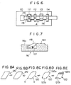
- With the method of making a cartridge shell plate in accordance with the present invention wherein the thin sheets having the dimensions as defined above are used and the four corner portions of each of the thin sheets are cut into predetermined shapes, it is possible to eliminate the problem that a large area of the thin metal sheet is wasted as in the case of the conventional method wherein, as shown in Figure 16, a thin metal sheet 50 larger than the developed dimensions of a cartridge shell plate as indicated by the broken line is punched out by use of a general-purpose pressing device 51 and is bent (as shown in Figure 17, with the conventional method, bending is generally carried out up to the step of processing the thin sheet 50 to have an approximately ship-like cross-sectional shape and then velvet ribbons 52, 52 are adhered to right and left edge portions of the thin sheet 50). Therefore, with the method of making a cartridge shell plate in accordance with the present invention, the thin metal sheets as the materials for cartridge shell plates can be utilized efficiently, and the amount of the thin metal sheets used can be reduced as compared with the conventional method. As a result, reduction of the cost of the cartridge loaded with a roll film can be achieved.
- Also, with the method of making a cartridge shell plate in accordance with the present invention wherein cutting of four corner portions of each thin sheet and bending of the thin sheet are carried out at independent work stations, the apparatus need not be greatly modified even though the shape of the formed cartridge shell plate is to be changed.
- Further, the processing conditions at one station can be adjusted to appropriate values independently of the other station, and therefore the cartridge shell plate can be formed accurately. Moreover, the cutting process and the bending process are separate from each other, a single die may be used for each process, and expensive dies, e.g. progressive dies, need not be used. Also, the use of a feed bar in the present invention enables increase of the processing speed.
- Other preferred embodiments of the present invention are laid down in the subclaims. In the following, the present invention is explained in greater detail by means of several embodiments thereof in conjunction with the accompanying drawings, wherein:
- Figures 1 and 2 are a plan view and a side view showing an embodiment of the apparatus for making a cartridge shell plate in accordance with the present invention,
- Figures 3 and 4 are a partially cutaway elevational view and a side view showing a part of the embodiment shown in Figure 7,
- Figures 5A to 5D are perspective views showing the steps for forming the cartridge shell plate by the apparatus for making a cartridge shell plate in accordance with the present invention,
- Figure 6 is a plan view showing an example of the apparatus for carrying out an embodiment of the method of making a cartridge shell plate in accordance with the present invention,
- Figure 7 is a sectional side view showing a part of the thin sheet conveyance means in the apparatus shown in Figure 12,
- Figures 8A to 8E are perspective views showing the steps of forming the cartridge shell plate by the method of making a cartridge shell plate in accordance with the present invention,
- Figure 9 is a perspective view showing the cartridge shell plate formed by the method of making a cartridge shell plate in accordance with the present invention and then bent into a cylindrical shape,
- Figures 10 and 11 are explanatory views showing the conventional method of making a cartridge shell plate,
- Figure 12 is a plan view showing an embodiment of the apparatus for adhering ribbons to a cartridge shell plate in accordance with the present invention,
- Figure 13 is a perspective view showing the pressure adherence unit for adhering velvet ribbon webs in the embodiment shown in Figure 12,
- Figures 14 and 15 are a plan view and a partially cutaway elevational view showing the ribbon cutting mechanism in the embodiment shown in Figure 12,
- Figure 16 is a side view showing a part of the ribbon cutting mechanism, and
- Figure 17 is a side view showing the thin sheet conveyance means in the embodiment shown in Figure 12.
- An embodiment of the apparatus for making a cartridge shell plate in accordance with the present invention will hereinbelow be described with reference to Figures 1 to 4 and Figures 5A to 5D.
- Referring to Figures 1 and 2, an embodiment of the apparatus for making a cartridge shell plate basically comprises a thin
sheet supply unit 110, a formingstation 113 composed of apress cutting unit 111 and apress bending unit 112, aribbon adherence station 116 composed of anadherence unit 114 and acutting unit 115, astacking unit 117, and afeed bar 118 for feedingthin metal sheets station 113 to theribbon adherence station 116. - The
feed bar 118 is provided on its upper surface withclaws drive unit 121. A plurality of thethin metal sheets sheet supply unit 110, and are supplied one after another onto thefeed bar 118 by a known supply means (not shown) constituted by an air suction cup or the like. At the time one of thethin sheets feed bar 118 is maintained stationary at the left end position in Figures 1 and 2 (i.e. at the position as indicated by the chain line in Figure 2), and thethin sheet 120 is supplied to the forward side of theleft claw 119a (i.e. to the right side thereof in Figures 1 and 2). As shown in Figure 5A, thethin sheet 120 supplied onto thefeed bar 118 in this manner has been cut into a rectangular shape so that the length and width dimensions thereof are equal to the developed length and width dimensions of the cartridge shell plate. - After the
thin sheet 120 is supplied onto thefeed bar 118, thefeed bar 118 is moved forward by a predetermined distance. As a result, thethin sheet 120 which has been supplied to the forward side of theclaw 119a is pushed and moved forward by theclaw 119a, and is stopped at a predetermined position in thepress cutting unit 111. At this time, thethin sheet 120 which has been supplied previously to the aforesaidthin sheet 120 supplied to the forward side of theclaw 119a is fed by theclaw 119b from thepress cutting unit 111 to thepress bending unit 112. Also, thethin sheet 120 which has been supplied previously to thethin sheet 120 supplied to the forward side of theclaw 119b is transferred from thepress bending unit 112 onto abucket conveyor 122 as will be described in detail later. Thepress cutting unit 111 is constituted by a known pressing device, and cuts the four corner portions of the rectangularthin sheet 120 so that thethin sheet 120 has a shape as shown in Figure 5B. At the time the pressing device of thepress cutting unit 111 is operated as mentioned above, a pressing device of thepress bending unit 112 is also activated to bend the right and left edge portions of thethin sheet 120 which has already been cut by thepress cutting unit 111. By the bending operation, thethin sheet 120 is formed to have an approximately ship-like cross-sectional shape as shown in Figure 5C. - Feeding of the
thin sheets bucket conveyor 122 will hereinbelow be described with reference to Figures 3 and 4. Figure 3 shows the lower section of thepress bending unit 112, as viewed in the direction as indicated by the arrow B in Figure 2, and Figure 4 shows thefeed bar 118 and thebucket conveyor 122. As shown in Figure 3, the pressing device of thepress bending unit 112 is provided with anupper die 123 and lower dies 124, 124, and rails 125 and 126 are disposed between the lower dies 124, 124. Therails sheet supply unit 110 to the position of entry into abucket 127 of thebucket conveyor 122. Specifically, as shown in Figure 4, arecess 129 is formed at the center of a thinsheet supporting surface 128 of each of thebuckets rails buckets sprocket wheel 132 in the direction as indicated by the arrow D. On the other hand, as shown in Figure 4, the surface of each of theclaws feed bar 118 opposite to the surface coming into contact with thethin sheet 120 is formed obliquely, and each of theclaws upper surface 118a of thefeed bar 118 by being urged by aspring 130. When thefeed bar 118 returns to its original position after feeding thethin sheets feed bar 118 returns leftward in Figures 1 and 2, theclaws thin sheets press cutting unit 111 and thepress bending unit 112 and are depressed by thethin sheets press cutting unit 111 and thepress bending unit 112. Therefore, thethin sheets press cutting unit 111 and thepress bending unit 112 are not returned toward the thinsheet supply unit 110. Thethin sheet 120 fed along therails press cutting unit 111 to thepress bending unit 112 is moved up by guide members (not shown), located on the lower dies 124, 124, and then placed on therails upper die 123 is moved down. - As shown in Figure 4, small-
diameter bucket claws sheet supporting surface 128 of eachbucket 127. Thefeed bar 118 feeds thethin sheet 120, which has been formed into the shape as shown in Figure 5C, onto thebucket 127 up to a position spaced from the position of contact with thebucket claws thin sheet 120 thus fed is pushed by thebucket claws next bucket 127 up to the position of contact with thebucket claws bucket 127 on which thethin sheet 120 is supported. In this manner, thethin sheets bucket conveyor 122 so that no space or only slight spaces intervene among thethin sheets - In the manner as mentioned above, the
thin sheets right edge portions left edge portions thin sheets adherence unit 114. At theadherence unit 114, continuous length velvet ribbon webs 135a and 135b on which an adhesive has been applied are pushed against theright edge portions left edge portions thin sheets rollers right edge portions left edge portions thin sheets cutting unit 115. At thecutting unit 115, the velvet ribbon webs 135a and 135b are cut between adjacentthin sheets cutter 138 swung in synchronization with the operation of thebucket conveyor 122. As a result, as shown in Figure 5D, thethin sheet 120 formed to have an approximately ship-like cross-sectional shape and having velvet ribbons 135a' and 135b' adhered to theright edge portion 120a and theleft edge portion 120b is obtained. - The
thin sheets unit 117. Thethin sheets - An embodiment of the method of making a cartridge shell plate in accordance with the present invention will hereinbelow be described with reference to Figures 6 to 9.
- Referring to Figure 6, an apparatus for carrying out the embodiment of the method of making a cartridge shell plate basically comprises a thin
sheet supply station 110, a cornerportion cutting station 111, a small-diameter bending station 112, afolding station 113, a both-edge bending station 114, thin sheet conveyance rails 115, 115 extending below thestations 110 to 114, and afeed bar 116 intermittently reciprocating in the direction as indicated by the arrow A between therails stations 110 to 114 are disposed so that the thin sheets setting sections are at equal intervals. - As shown in Figure 7, the
feed bar 116 is provided with fiveclaws claw 118 is shown in Figure 13) each of which is projected upward of aupper surface 116a of thefeed bar 116 by being urged by aspring 117. Theclaws stations 110 to 114. The thinsheet supply station 110 houses a plurality ofthin metal sheets thin sheets rails feed bar 116 by a known supply means (not shown) constituted by an air suction cup or the like. At the time one of thethin sheets feed bar 116 is maintained stationary at the left end position in Figure 12, and thethin sheet 120 is supplied to the forward side of the left end claw 118 (i.e. to the right side thereof in Figure 12). As shown in Figure 8A, thethin sheet 120 supplied onto thefeed bar 116 in this manner has been cut into a rectangular shape so that the length and width dimensions thereof are equal to the developed length and width dimensions of the cartridge shell plate. - After the
thin sheet 120 is supplied onto thefeed bar 116, thefeed bar 116 is moved forward by a distance equal to the intervals of theclaws thin sheet 120 which has been supplied to the forward side of theleft end claw 118 is pushed and moved forward by theclaw 118, and is stopped at a predetermined position in the cornerportion cutting station 111. At the time thefeed bar 116 is moved in this manner, thethin sheet 120 which has been present in the cornerportion cutting station 111 is fed to the small-diameter bending station 112, and thethin sheet 120 which has been present in the small-diameter bending station 112 is fed to thefolding station 113. The cornerportion cutting station 111 is constituted by a known pressing device, and cuts four corner portions of the rectangularthin sheet 120 so that thethin sheet 120 has a shape as shown in Figure 8B. Simultaneously with activation of the cornerportion cutting station 111 as mentioned above, the small-diameter bending station 112, thefolding station 113 and the both-edge bending station 114 are activated. - The small-
diameter bending station 112 is constituted by a pressing device, and imparts small-diameter bends R, R to two cut corner portions of thethin sheet 120 as shown in Figure 8c. The bends R, R facilitate fitting of cartridge caps to thethin sheet 120 bent into a cylindrical shape as shown in Figure 9. Thefolding station 113 folds theedge portion 120a of thethin sheet 120 and forms thethin sheet 120 into the shape as shown in Figure 8D. Thereafter, the both-edge bending station 114 bends theedge portion 120a and theother edge portion 120b of thethin sheet 120 into a predetermined shape by press forming. - By the press forming at the both-
edge bending station 114, thethin sheet 120 is formed to have an approximately ship-like cross-sectional shape as shown in Figure 8E. Thethin sheets feed bar 116 out of the both-edge bending station 114, and fed into, for example, a velvet ribbon adherence station (not shown), directly or after being stacked one upon another. At the velvet ribbon adherence station, velvet ribbons are adhered to theedge portions thin sheet 120. Then thethin sheet 120 is bent into a cylindrical shape so thatvelvet ribbons thin sheet 120 bent cylindrically, and caps are fitted to thethin sheet 120. The bending into the cylindrical shape, insertion of the spool, and fitting of caps are carried out in accordance with a known method. - As shown in Figure 7, the surface of each of the
claws feed bar 116 opposite to the surface coming into contact with thethin sheet 120 is formed obliquely. When thefeed bar 116 returns to its original position after feeding thethin sheets feed bar 16 returns leftward in Figure 6, theclaws thin sheets stations 111 to 114 and are depressed by thethin sheets stations 111 to 114. Therefore, thethin sheets stations 111 to 114 are not returned toward the thinsheet supplying station 110. - The folding angle at the
folding station 113 may be changed slightly in accordance with the width of the port and the post-processes. In this embodiment, changes of the folding angle can be achieved by changing the link length of thefolding station 113. - The small-
diameter bending station 112, thefolding station 113 and the both-edge bending station 114 may be replaced by a single press forming device. Also in such a case, the four corner cutting shape of thethin sheet 120 can be changed simply by changing the dies at the cornerportion cutting station 111. The shapes at the other sections can be changed simply by changing the dies of the press forming device. - With the aforesaid embodiment of the method of making a cartridge shell plate wherein the
thin sheet 120 cut to have dimensions equal to the developed length and width dimensions of the cartridge shell plate is used, the cartridge shell plate can be formed from a 3,360mm²thin sheet 120 in the case of the 135 film. In the case where the cartridge shell plate is formed by use of a general-purpose pressing device as in the conventional method, a 3,486mm² thin sheet is necessary per cartridge shell plate for the 135 film for example. Thus, with the method in accordance with the present invention, the amount of the thin metal sheets used can be reduced by approximately 3.8% as compared with the conventional method. - The present invention will hereinbelow be described in further detail with reference to the accompanying drawings.
- Figure 12 shows an embodiment of the apparatus for adhering ribbons to a cartridge shell plate in accordance with the present invention, Figure 13 shows a
pressure adherence unit 10 in the embodiment shown in Figure 12, and Figures 14 and 15 show in detail the major part of aribbon cutting unit 20 in the embodiment shown in Figure 12.Thin metal sheets thin sheets supply unit 12 onto a conveyance means 13 constituted by a belt conveyor or the like. At this time, each of thethin sheets thin sheet 11 is bent into a cylindrical shape faces up. In the course of conveyance of thethin sheets thin sheets frequency heaters thin sheets heaters - The heated
thin sheets bucket conveyor 15 which conveys them in the direction as indicated by the arrow A from apressure adherence unit 10 to a stackingunit 30 via aribbon cutting unit 20. As shown in detail in Figure 6, small-diameter claws buckets bucket conveyor 15. The positions of thethin sheets claws thin sheets thin sheet 11 and the trailing edge of the precedingthin sheet 11, and thethin sheets pressure adherence station 10, continuous lengthvelvet ribbon webs 21a and 21b whose back surfaces have been coated with an adhesive are applied respectively onrollers velvet ribbon webs 21a and 21b are stored in the form of rolls wound around supply shafts (not shown), and the leading end portions thereof are adhered to the right and left edge portions of thethin sheets velvet ribbon webs 21a and 21b is effected by supplying thevelvet ribbon webs 21a and 21b with the adhesive-coated surfaces facing down, pushing thevelvet ribbon web 21a against the right edge portions 11a, 11a, ... of thethin sheets thin sheets rollers 23b. In this manner, thevelvet ribbon webs 21a and 21b are adhered respectively to the right edge portions 11a, 11a, ... of the heatedthin sheets - The continuous length
velvet ribbon webs 21a and 21b adhered to thethin sheets thin sheets thin sheets velvet ribbon webs 21a and 21b and fed into theribbon cutting unit 20 in this condition. Theribbon cutting unit 20 is composed of a ribbon cutting mechanism 25a disposed beside the right edge portions 11a, 11a, ... of thethin sheets ribbon cutting mechanism 25b disposed beside the left edge portions 11b, 11b, ... of thethin sheets ribbon cutting mechanisms 25a and 25b are symmetric in shape with respect to each other, and therefore cutting of thevelvet ribbon webs 21a and 21b will be described below by taking the ribbon cutting mechanism 25a as an example. As shown in Figure 12, the ribbon cutting mechanism 25a is provided with a loop-like chain 26, and a plurality ofcutter units cutter units chain 26. Thechain 26 is disposed so that it is parallel with thebucket conveyor 15 by the side of thethin sheets velvet ribbon web 21a has been adhered. Also,sprocket wheels chain 26 is wound are connected to, for example, a drive unit of thebucket conveyor 15 and are rotated continuously to move thechain 26 in the direction as indicated by the arrow B at a speed equal to the movement speed of thebucket conveyor 15. Therefore, thecutter units thin sheets thin sheets cutter units cutters cutter unit 27 is being moved beside eachthin sheet 11 in synchronization therewith, thecutters velvet ribbon web 21a at the leading edge and the trailing edge of thethin sheet 11. The operations of thecutters - Figure 14 is a plan view of the
cutter unit 27, and Figure 4 is an elevational view of the same located beside thethin sheets cutter 29 is swingable in the direction as indicated by the arrow C around aswing shaft 31. Also, thecutter unit 27 is provided with awork holder 33 swingable in the direction as indicated by the arrow D around aswing shaft 32. Also, thecutter unit 27 is provided with a locatingpin 34 supported moveably in the direction as indicated by the arrow E (i.e. in the horizontal direction), and a rear end of the locatingpin 34, i.e. the left end thereof in Figure 15, is secured to amovement member 36 on which aroller 35 is supported rotatably. The path of movement of thecutter unit 27 is defined bymovement defining rollers pin 34 is urged rearward by aspring 41, so that theroller 35 contacts aplate cam 42 as shown in Figure 14. On the other hand, eachcutter 29 is connected with a verticaly extendingconnection member 44, aroller 45 is rotatably supported on the lower end portion of theconnection member 44, and theconnection member 44 is urged upward by aspring 46. Therefore, as shown in Figure 16, theroller 45 contacts a bottom surface of aplate cam 47. - Slightly before the
cutter unit 27 arrives at the ribbon cutting position, i.e. the position as shown in Figure 3, theroller 35 advances onto a protrusion 42a of theplate cam 42. As a result, the locatingpin 34 is moved toward thebucket conveyor 15 against the urging force of thespring 41, and the leading end portion of the locatingpin 34 fits into a locating hole 16a of one of thebuckets cutter unit 27 in synchronization with the movement of thebucket 16. Also, as the locatingpin 34 is moved in this manner, themovement member 36 moves toward thebucket conveyor 15. Therefore, thework holder 33 which has been maintained at the waiting position spaced upward from thethin sheet 11 is swung clockwise in Figure 15, and holds thevelvet ribbon web 21a from above. Thereafter, thecutter unit 27 arrives at the ribbon cutting position as shown in Figure 14. At this time, theroller 45 enters a recess 47a of theplate cam 47. Therefore, theconnection member 44 is moved up by the urging force of thespring 46, and thecutters thin sheet 11 are swung counter-clockwise in Figure 15, enter between thethin sheet 11 and the adjacentthin sheets velvet ribbon web 21a at two positions. Thecutter units chain 26 at intervals two times the array intervals of thethin sheets cutter units velvet ribbon web 21a at each of thethin sheets cutter unit 27 is moved together with thethin sheet 11 after thevelvet ribbon web 21a has been cut by thecutter unit 27 in the manner as mentioned above, thecutters thin sheet 11 by the action of theplate cam 47, and thework holder 33 is moved up from thevelvet ribbon web 21a. Thus thecutters work holder 33 return to their waiting positions. The other velvet ribbon web 21b is cut in the same manner as mentioned above by theribbon cutting mechanism 25b. - The
thin sheets velvet ribbon webs 21a and 21b are adhered to the right and left edge portions are conveyed by thebucket conveyor 15 to the stackingunit 30 and are stacked one upon another. Thethin sheets
Claims (17)
- An apparatus for making a cartridge shell plate for the manufacture of a cylindrical cartridge for accommodating a photographic film, comprising a sheet supply unit (110), a forming station (113) for cutting thin metal sheets (120) sequentially into a predetermined shape and bending same into an approximately ship-like cross-sectional shape, a velvet ribbon adherence station (116) to adhere velvet ribbons to right and left edge portions of the thin sheets (120), and a stacking unit (117) for collecting the finished prefabricated cartridge shell plates,
characterised by,
a feed means comprising a reciprocating feed bar mechanism (118, 119, 121) for intermittently feeding said thin sheets (120) from the sheet supply unit (110) through the forming station (113) to the velvet ribbon adherence station (116) while maintaining each of said thin sheets (120) in a predetermined orientation adapted to transfer said sheets (120) one after another to a continuous conveyance means (15) of the velvet ribbon adherence station (116), conveying said thin sheets (120) disposed side by side so that a leading edge of each of the thin sheets (120) contacts or almost contacts a trailing edge of the preceding thin sheet (120) wherein velvet ribbons (135a', 135b') from velvet ribbon webs (135a, 135b) are adhered to the opposite right and left edge portions of each of said thin sheets (120). - An apparatus as claimed in claim 1, characterised in that, the feed bar mechanism comprises a feed bar (118) intermittently reciprocated and provided with a plurality of claws (119a, 119b, 119c) disposed along the feed bar (118) at predetermined intervals for pushing forward said thin sheets (120), each of said claws (119a, 119b, 119c) having an oblique surface opposite to a surface which is adapted to engage a thin sheet (120) each of said claws (119a, 119b, 119c) being urged by a spring (130) to protrude from an upper surface of the feed bar during a feed operation of the feed bar (118) and to be depressable during a return cycle of the feed bar (118).
- An apparatus as claimed in Claims 1 and 2, characterised in that, the velvet ribbon adherence station (116) is provided with a bucket conveyor (122) composed of a plurality of buckets (127) each for supporting a single thin sheet (120) thereon.
- An apparatus as claimed in Claim 3, characterised in that, small diameter bucket claws (131) are provided to protrude from thin sheet supporting surfaces (128) of the bucket (127) for defining the positions of said thin sheets (120) disposed on said buckets (127).
- An apparatus as claimed in at least one of the preceding claims 1 to 4, characterised in that, each of said thin sheets (120) has length and width dimensions equal to the developed length and width dimensions of the finished prefabricated cartridge shell plate.
- An apparatus as claimed in at least one of the preceding Claims 1 to 5, characterised in that, the thin sheet supply unit (110) is disposed above the feed bar (118).
- An apparatus as claimed in at least one of the preceding claims 1 to 6, characterised in that, the forming station (113) comprises a press cutting unit (111) and a press bending unit (112) disposed downstream of the press cutting unit (111).
- An apparatus as claimed in Claim 7, characterised in that, the press cutting unit (111) comprises a corner portion cutting station, the press bending unit (112) comprises a small-diameter bending station, the forming station (113) comprises a folding station, the velvet ribbon adherent station (116) comprises an adherence unit (114) and a cutting unit (115), with thin sheet conveyance rails extending below the thin sheet supply unit (110) and the aforeindicated means (111-114), with a feed bar (118) being supported to intermittently reciprocate in the lengthwise direction between rails.
- An apparatus as claimed in at least one of the preceding Claims 1 to 8, wherein said velvet ribbon adhering station (116) comprises:
a conveyance means (13) for continuously conveying a plurality of said thin sheets (11) disposed side by side so that a leading edge of each of said thin sheets is adjacent to a trailing edge of the preceding thin sheet (11),
a pressure adherence means (10) for pushing two continuous length velvet ribbon webs (21a, 21b), on which an adhesive has been applied, respectively against right and left edge portions of said thin sheets (11) which are being conveyed, thereby to continuously adhere said velvet ribbon webs (21a, 21b) to said right and left edge portions of said thin sheets (11), and
a velvet ribbon cutting mechanism (20) for cutting the velvet ribbon webs (21a, 21b) characterised in that, the velvet ribbon cutting mechanism (20) comprises a plurality of circulating cutter units (27) so that said cutter units (27) are moved beside said thin sheets (11), to which said velvet ribbon webs (21a, 21b) have been adhered, in the same direction as the direction of conveyance of said thin sheets and in synchronization with same, said cutter units (27) comprising swinging cutters (29), which are being moved in synchronization with said thin sheets (11), so that said cutters enter between the leading edge and the trailing edge of said thin sheets (11) adjacent to each other and cut said velvet ribbon webs (21a, 21b). - An apparatus as claimed in Claim 9 characterised in that, said conveyance means (13) comprises a bucket conveyor composed of a plurality of buckets (16) each for supporting a single thin sheet (11) thereon.
- An apparatus as claimed in Claim 10 characterised in that, small-diameter claws (17) are provided to protrude from thin sheet supporting surfaces of said buckets (16) for defining the positions of said thin sheets (11) disposed on said buckets (16) so that the leading edge of each of said thin sheets (11) is adjacent to the trailing edge of the preceding thin sheet(11).
- An apparatus as defined in at least one of the preceding claims 9 to 11, characterised in that, two ribbon cutting mechanisms (20) are disposed one on velvet either side of said thin sheets (11) to which said velvet ribbon webs (21a, 21b) have been adhered, and said cutter units (27) of each of said velvet ribbon cutting mechanisms (20) are secured at equal
intervals to a loop-like chain (26) rotated at the same speed as the conveyance means (13) of said thin sheets (11). - An apparatus as claimed in at least one of the preceding Claims 9 to 12, characterised in that, each of said cutter units (27) is provided with a work holder (33) swingable for holding said velvet ribbon web (21a, 21b).
- An apparatus as claimed in at least one of the preceding Claims 9 to 13, characterised in that, each of said cutter units (27) is provided with a locating pin (34) for engaging with a locating hole (16c) of said conveyance means (13), thereby to ensure the synchronous movement of said cutter unit (27) with respect to said thin sheet (11).
- A method of making cartridge shell plates, through an apparatus as claimed in Claim 1, characterised by
conveying thin metal sheets (10) from a sheet supply unit (110) through a forming station (113) to a velvet ribbon adherence station (116) while maintaining them at a predetermined orientation,
at the forming station (113) cutting four corner portions of each of the thin metal sheets (120) sequentially into a predetermined shape and bending them into an approximately ship-like cross-sectional shape,
transferring the sheets (120) one after another to a continuous conveyance means (118,119) of the velvet ribbon adherence station (116), and
conveying said thin sheets (120) disposed side by side so that a leading edge of each of the thin sheets (120) contacts or almost contacts a trailing edge of the preceding thin sheet (120) wherein velvet ribbons (135a',135b') from velvet ribbon webs (135a,135b) are adhered to the opposite right and left edge portions of each of said thin sheets. - A method of making cartridge shell plates as claimed in Claim 15, characterised in that before adhering velvet ribbons to right and left edge portions of each of said cartridge shell plates, the following steps are performed:
intermittently conveying the thin metal sheets (120) which have been cut so that each of said thin sheets (120) has length and width dimensions equal to the developed length and width dimensions of a cartridge shell plate one after another by the conveyance means (118,119), said metal sheets (120) are conveyed such that each top surface is to form an inner side of a completed film cartridge,
cutting four corner portions of each of said thin sheets (120) into predetermined shapes and then bending each of said thin sheets (120) so that it has a predetermined, approximately ship-like cross-sectional shape at a cutting process station (111) and a bending process station (112) disposed along said conveyance means (118,119) and,
conveying said cartridge shell plates in a way that the inner surface of each shell plate maintains top. - A method of making a cartridge shell plate as claimed in Claim 15, characterised by the steps of
cutting four corner portions of each of said thin sheets (11, 120) into said predetermined shapes
adhering velvet ribbons (135a', 135b') to right and left edge portions of each of said thin sheets (11, 120) from a pair of continuous velvet ribbon webs (135a, 135b),
subsequently cutting said velvet ribbon webs (21a, 21b, 135a, 135b) between the front and trailing edges of adjacent thin sheets (11, 120) and stacking the pre-manufactured cartridge shell plates into a container (117) for bending into a cylindrical shape to insert a film spool therein and attach end caps on the cylindrically bent cartridge shell plate from both sides.
Priority Applications (1)
| Application Number | Priority Date | Filing Date | Title |
|---|---|---|---|
| EP19920100883 EP0480913B1 (en) | 1986-09-18 | 1987-09-17 | Apparatus for adhering ribbons to cartridge shell plate |
Applications Claiming Priority (6)
| Application Number | Priority Date | Filing Date | Title |
|---|---|---|---|
| JP219942/86 | 1986-09-18 | ||
| JP21994286A JPH0686268B2 (en) | 1986-09-18 | 1986-09-18 | Ribbon sticking device for patrone body plate |
| JP231423/86 | 1986-09-30 | ||
| JP23142286A JPS6385625A (en) | 1986-09-30 | 1986-09-30 | Apparatus for producing barrel sheet of film cartridge |
| JP231422/86 | 1986-09-30 | ||
| JP23142386A JPS6385626A (en) | 1986-09-30 | 1986-09-30 | Apparatus for producing barrel sheet of film cartridge |
Related Child Applications (1)
| Application Number | Title | Priority Date | Filing Date |
|---|---|---|---|
| EP92100883.5 Division-Into | 1987-09-17 |
Publications (3)
| Publication Number | Publication Date |
|---|---|
| EP0260701A2 EP0260701A2 (en) | 1988-03-23 |
| EP0260701A3 EP0260701A3 (en) | 1989-12-13 |
| EP0260701B1 true EP0260701B1 (en) | 1994-12-28 |
Family
ID=27330379
Family Applications (2)
| Application Number | Title | Priority Date | Filing Date |
|---|---|---|---|
| EP19920100883 Expired - Lifetime EP0480913B1 (en) | 1986-09-18 | 1987-09-17 | Apparatus for adhering ribbons to cartridge shell plate |
| EP19870113645 Expired - Lifetime EP0260701B1 (en) | 1986-09-18 | 1987-09-17 | Method of and apparatus for making cartridge shell plate for films |
Family Applications Before (1)
| Application Number | Title | Priority Date | Filing Date |
|---|---|---|---|
| EP19920100883 Expired - Lifetime EP0480913B1 (en) | 1986-09-18 | 1987-09-17 | Apparatus for adhering ribbons to cartridge shell plate |
Country Status (3)
| Country | Link |
|---|---|
| US (2) | US4862579A (en) |
| EP (2) | EP0480913B1 (en) |
| DE (2) | DE3751500T2 (en) |
Families Citing this family (11)
| Publication number | Priority date | Publication date | Assignee | Title |
|---|---|---|---|---|
| JPH0833624B2 (en) * | 1988-05-13 | 1996-03-29 | 富士写真フイルム株式会社 | Film winding supply method and device |
| JPH0616953B2 (en) * | 1989-05-16 | 1994-03-09 | 東洋製罐株式会社 | Equipment for manufacturing outer cans for dry batteries |
| DE3928683A1 (en) * | 1989-08-30 | 1991-03-07 | Agfa Gevaert Ag | METHOD FOR PRODUCING FILM TAPES |
| JP2785152B2 (en) * | 1990-04-26 | 1998-08-13 | コニカ株式会社 | Patrone body forming equipment |
| US5246521A (en) * | 1990-07-12 | 1993-09-21 | Fuji Photo Film Co., Ltd. | Film container, teremp and method of bonding teremp to shell plate of film cartridge |
| US5125254A (en) * | 1990-12-06 | 1992-06-30 | Eastman Kodak Company | Apparatus for forming a very open shell for lateral loading of product |
| JP2744855B2 (en) * | 1991-04-17 | 1998-04-28 | 富士写真フイルム株式会社 | Method and apparatus for attaching telem to photo film patrone |
| JP3109777B2 (en) * | 1993-03-11 | 2000-11-20 | 富士写真フイルム株式会社 | Photo film cartridge body plate stacking device |
| US5766411A (en) * | 1995-08-28 | 1998-06-16 | Paragon Trade Brands. Inc. | Apparatus for producing a garment with barrier device |
| US20030033706A1 (en) * | 2001-08-14 | 2003-02-20 | Fuji Photo Film Co., Ltd. | Method and apparatus for manufacturing film cartridge plate |
| KR101909111B1 (en) * | 2016-08-24 | 2018-10-17 | 박길미 | Apparatus for attaching a reflecting film for LED mounting frame |
Family Cites Families (25)
| Publication number | Priority date | Publication date | Assignee | Title |
|---|---|---|---|---|
| US1780049A (en) * | 1928-10-01 | 1930-10-28 | Seattle Astoria Iron Works | Feed device for can-body-forming machines |
| US2407253A (en) * | 1943-10-28 | 1946-09-10 | Guy O Conner | Forming machine |
| US2682909A (en) * | 1947-06-06 | 1954-07-06 | M B Claff & Sons Inc | Machine for making reinforced webs |
| US3053130A (en) * | 1958-06-03 | 1962-09-11 | Koppers Co Inc | Chain tool carrier with longitudinally overlapping cutters |
| US3228272A (en) * | 1963-01-18 | 1966-01-11 | Reynolds Metals Co | Method and apparatus for bending and cutting a partially slitted long tube to produce a plurality of relatively short tubes |
| US3466961A (en) * | 1965-06-01 | 1969-09-16 | Vni I P Konsturktorsky I Metal | Cutting elements of flying shears |
| US3364551A (en) * | 1965-10-23 | 1968-01-23 | Kahle Engineering Company | Means for assembling cartridges |
| US3533881A (en) * | 1966-04-14 | 1970-10-13 | Globe Ind Inc | Method and machine for combining elongated metal panels with core boards |
| SE324973B (en) * | 1968-11-19 | 1970-06-15 | Moelnlycke Ab | |
| AT327653B (en) * | 1973-05-18 | 1976-02-10 | Boehler & Co Ag Geb | CUTTING DEVICE |
| US3908342A (en) * | 1973-10-26 | 1975-09-30 | Fmc Corp | Heat sealing machine |
| US3877626A (en) * | 1974-05-21 | 1975-04-15 | Nat Acceptance Company Of Amer | Apparatus for cutting a continuous element of indeterminate length into predetermined lengths |
| JPS5531539Y2 (en) * | 1974-08-02 | 1980-07-28 | ||
| US4114550A (en) * | 1977-03-14 | 1978-09-19 | Toyo Seikan Kaisha, Ltd. | Apparatus for use in an automatic and continuous manufacture line for manufacturing the outer cylindrical cases of dry cells |
| US4106420A (en) * | 1977-03-24 | 1978-08-15 | Hokkai Can Co., Ltd. | Apparatus for forming cans |
| US4087312A (en) * | 1977-08-01 | 1978-05-02 | Maltese Peter C | Feeding-applying lettering tape |
| US4224888A (en) * | 1978-06-08 | 1980-09-30 | Hokkai Can Co., Ltd. | Method for forming cans |
| JPS5577949A (en) * | 1978-12-07 | 1980-06-12 | Fuji Kiki Kogyo Kk | Molding device of photographic patrone or the like |
| US4404720A (en) * | 1979-06-26 | 1983-09-20 | Western Electric Company, Inc. | Apparatus for forming a metallic tape into a tube having an overlapped seam |
| CA1146129A (en) * | 1980-08-22 | 1983-05-10 | Edmund Radzins | Apparatus for applying elastic ribbon segments to diapers |
| DE3118210A1 (en) * | 1981-05-08 | 1982-12-02 | Agfa-Gevaert Ag, 5090 Leverkusen | CAPSULE FOR A FILM CARTRIDGE AND METHOD FOR THE PRODUCTION THEREOF |
| GB2129339A (en) * | 1982-10-29 | 1984-05-16 | Kenneth Carter | A method of forming a sheet |
| JPS59143841A (en) * | 1983-02-03 | 1984-08-17 | Fuji Photo Film Co Ltd | Winding method and device for film |
| US4680079A (en) * | 1984-03-16 | 1987-07-14 | Fujitsu Limited | Printed circuit board laminating apparatus |
| US4581970A (en) * | 1985-01-10 | 1986-04-15 | Hanson Douglas R | Machine for prescoring English muffins or the like |
-
1987
- 1987-09-17 DE DE19873751500 patent/DE3751500T2/en not_active Expired - Lifetime
- 1987-09-17 EP EP19920100883 patent/EP0480913B1/en not_active Expired - Lifetime
- 1987-09-17 DE DE19873750921 patent/DE3750921T2/en not_active Expired - Lifetime
- 1987-09-17 EP EP19870113645 patent/EP0260701B1/en not_active Expired - Lifetime
- 1987-09-18 US US07/098,656 patent/US4862579A/en not_active Expired - Lifetime
-
1988
- 1988-05-09 US US07/190,800 patent/US4891089A/en not_active Expired - Lifetime
Also Published As
| Publication number | Publication date |
|---|---|
| DE3751500T2 (en) | 1996-02-22 |
| DE3751500D1 (en) | 1995-10-05 |
| EP0260701A2 (en) | 1988-03-23 |
| EP0260701A3 (en) | 1989-12-13 |
| EP0480913B1 (en) | 1995-08-30 |
| EP0480913A3 (en) | 1992-11-04 |
| DE3750921D1 (en) | 1995-02-09 |
| DE3750921T2 (en) | 1995-05-11 |
| EP0480913A2 (en) | 1992-04-15 |
| US4862579A (en) | 1989-09-05 |
| US4891089A (en) | 1990-01-02 |
Similar Documents
| Publication | Publication Date | Title |
|---|---|---|
| EP0260701B1 (en) | Method of and apparatus for making cartridge shell plate for films | |
| US4314403A (en) | Machine for automatically stacking plate groups for storage batteries | |
| CA1243417A (en) | Printed circuit board laminating apparatus | |
| CA1073671A (en) | Method and apparatus for manufacture of swatch bearing sheets | |
| CN100415469C (en) | Apparatus and method for making cellular shade material | |
| US2772880A (en) | Sheet stacker | |
| JP2010247291A (en) | Flat plate punching device | |
| JPH07112753B2 (en) | Method and apparatus for making a self-adhesive sticky note block | |
| US5609556A (en) | Method and apparatus for manufacturing bags with strap-shaped carrying handles | |
| AU651905B2 (en) | An apparatus for feeding sheet-like blanks to a deep-drawing machine | |
| JPH081773A (en) | Device for producing blank for collar of pack with hinged lid having circular or polygonal longitudinal edge part | |
| JP3604041B2 (en) | Lid member mounting method and device | |
| US4326704A (en) | Tipping machine | |
| JPH1034770A (en) | Semiautomatic box making apparatus and folding working-table for the same | |
| JPH0553256B2 (en) | ||
| JPH0686268B2 (en) | Ribbon sticking device for patrone body plate | |
| GB2151979A (en) | Face veneer manufacturing apparatus | |
| JPH0426282B2 (en) | ||
| US6159326A (en) | Method of and apparatus for applying light-shield member to photosensitive member | |
| US4589947A (en) | Straw adhering apparatus for beverage vessels | |
| US6488800B1 (en) | Method for changing pulling off a cover web of a production roll to a storing roll | |
| US4818328A (en) | Process for manufacturing sacks, bags, and the like | |
| HU194093B (en) | Method and apparatus for assembling materials to be compressed particularly furniture industrial workpiece and coating material | |
| US1302735A (en) | Machine for affixing stamps and the like. | |
| JPS6385626A (en) | Apparatus for producing barrel sheet of film cartridge |
Legal Events
| Date | Code | Title | Description |
|---|---|---|---|
| PUAI | Public reference made under article 153(3) epc to a published international application that has entered the european phase |
Free format text: ORIGINAL CODE: 0009012 |
|
| AK | Designated contracting states |
Kind code of ref document: A2 Designated state(s): DE NL |
|
| RHK1 | Main classification (correction) |
Ipc: B26D 1/60 |
|
| PUAL | Search report despatched |
Free format text: ORIGINAL CODE: 0009013 |
|
| AK | Designated contracting states |
Kind code of ref document: A3 Designated state(s): DE NL |
|
| 17P | Request for examination filed |
Effective date: 19900312 |
|
| 17Q | First examination report despatched |
Effective date: 19910614 |
|
| GRAA | (expected) grant |
Free format text: ORIGINAL CODE: 0009210 |
|
| AK | Designated contracting states |
Kind code of ref document: B1 Designated state(s): DE NL |
|
| PG25 | Lapsed in a contracting state [announced via postgrant information from national office to epo] |
Ref country code: NL Effective date: 19941228 |
|
| XX | Miscellaneous (additional remarks) |
Free format text: TEILANMELDUNG 92100883.5 EINGEREICHT AM 17/09/87. |
|
| REF | Corresponds to: |
Ref document number: 3750921 Country of ref document: DE Date of ref document: 19950209 |
|
| NLV1 | Nl: lapsed or annulled due to failure to fulfill the requirements of art. 29p and 29m of the patents act | ||
| PLBE | No opposition filed within time limit |
Free format text: ORIGINAL CODE: 0009261 |
|
| STAA | Information on the status of an ep patent application or granted ep patent |
Free format text: STATUS: NO OPPOSITION FILED WITHIN TIME LIMIT |
|
| 26N | No opposition filed | ||
| PGFP | Annual fee paid to national office [announced via postgrant information from national office to epo] |
Ref country code: DE Payment date: 20061031 Year of fee payment: 20 |