EP0260435A1 - Composite building panels - Google Patents
Composite building panels Download PDFInfo
- Publication number
- EP0260435A1 EP0260435A1 EP87111611A EP87111611A EP0260435A1 EP 0260435 A1 EP0260435 A1 EP 0260435A1 EP 87111611 A EP87111611 A EP 87111611A EP 87111611 A EP87111611 A EP 87111611A EP 0260435 A1 EP0260435 A1 EP 0260435A1
- Authority
- EP
- European Patent Office
- Prior art keywords
- laths
- core panel
- composite building
- building element
- frame
- Prior art date
- Legal status (The legal status is an assumption and is not a legal conclusion. Google has not performed a legal analysis and makes no representation as to the accuracy of the status listed.)
- Granted
Links
Images


Classifications
-
- E—FIXED CONSTRUCTIONS
- E04—BUILDING
- E04C—STRUCTURAL ELEMENTS; BUILDING MATERIALS
- E04C2/00—Building elements of relatively thin form for the construction of parts of buildings, e.g. sheet materials, slabs, or panels
- E04C2/30—Building elements of relatively thin form for the construction of parts of buildings, e.g. sheet materials, slabs, or panels characterised by the shape or structure
- E04C2/38—Building elements of relatively thin form for the construction of parts of buildings, e.g. sheet materials, slabs, or panels characterised by the shape or structure with attached ribs, flanges, or the like, e.g. framed panels
- E04C2/386—Building elements of relatively thin form for the construction of parts of buildings, e.g. sheet materials, slabs, or panels characterised by the shape or structure with attached ribs, flanges, or the like, e.g. framed panels with a frame of unreconstituted or laminated wood
-
- E—FIXED CONSTRUCTIONS
- E04—BUILDING
- E04C—STRUCTURAL ELEMENTS; BUILDING MATERIALS
- E04C2/00—Building elements of relatively thin form for the construction of parts of buildings, e.g. sheet materials, slabs, or panels
- E04C2/30—Building elements of relatively thin form for the construction of parts of buildings, e.g. sheet materials, slabs, or panels characterised by the shape or structure
- E04C2/38—Building elements of relatively thin form for the construction of parts of buildings, e.g. sheet materials, slabs, or panels characterised by the shape or structure with attached ribs, flanges, or the like, e.g. framed panels
- E04C2/382—Building elements of relatively thin form for the construction of parts of buildings, e.g. sheet materials, slabs, or panels characterised by the shape or structure with attached ribs, flanges, or the like, e.g. framed panels with a frame of concrete or other stone-like substance
-
- E—FIXED CONSTRUCTIONS
- E04—BUILDING
- E04C—STRUCTURAL ELEMENTS; BUILDING MATERIALS
- E04C2/00—Building elements of relatively thin form for the construction of parts of buildings, e.g. sheet materials, slabs, or panels
- E04C2/30—Building elements of relatively thin form for the construction of parts of buildings, e.g. sheet materials, slabs, or panels characterised by the shape or structure
- E04C2/38—Building elements of relatively thin form for the construction of parts of buildings, e.g. sheet materials, slabs, or panels characterised by the shape or structure with attached ribs, flanges, or the like, e.g. framed panels
- E04C2/384—Building elements of relatively thin form for the construction of parts of buildings, e.g. sheet materials, slabs, or panels characterised by the shape or structure with attached ribs, flanges, or the like, e.g. framed panels with a metal frame
Definitions
- the present invention relates to composite building elements and in particular to composite building panels which have various applications in the building industry, for example for building walls, floors, ceilings and roofs.
- One popular method of building a wall is to build a timber frame which is then filled with glass wool. Since these timber frames are not highly shear resistant, a plywood sheathing is usually nailed to the timber frame. However, the plywood sheathing is relatively expensive and it does not always provide the building element with sufficient shear resistance. Insufficient shear resistance is also experienced when a chip board is nailed to the timber frame instead of plywood. The use of a chip board is furthermore disadvantageous because of the excessive weight of the chip board which is required to obtain satisfactory strength.
- GB patent specification 1 587 012 it is suggested to close a wall space defined by the timber frames of a building with a foamed polyurethane or a foamed polystyrene.
- such timber frames of which the wall space is filled with foamed polyurethane or polystyrene sheets have several disadvantages when building the walls.
- the size of the frame and of the foam sheet or slab must be very well adjusted to each other in order to avoid gaps between the frame and the foam sheet or slab.
- Special seals have been suggested in GB patent specification 1 587 012 in order to fill such difficult to avoid gaps, but such seals increase the installation costs.
- the timber frame has much lower insulation properties than the foam sheet or slab and therefore forms thermal bridges in the building panel.
- a module block which consists of two parallel fiber plates. To each fiber plate two parallel laths are fixed. For connecting the two fiber plates with each other, side plates, for example fiber plates or chip boards, are fixed to the laths perpendicularly to the first two fiber plates.Between the four plates, an insulation material such as rock-wool is placed. However, fiber-plates, ply-wood or chip boards of heavy weight are required for providing sufficient shear strength to the module block. Furthermore, the side plates produced of fiber plates, chip board or ply-wood boards have insufficient insulation properties and therefore form thermal bridges in the module block.
- a composite building element which does not only have good insulation properties but also high strength, in particular high shear resistance. It is also desirable to provide a building element which can be prefabricated and easily installed and which preferably has a relatively low weight.
- the present invention provides a composite building element which comprises
- the composite building element of the present invention has a surprisingly high resistance to shearing forces. Furthermore, the composite building element of the present invention does not provide thermal bridges.
- the composite building element comprises a core panel 1 of a rigid foamed material of an expanded synthetic resin, such rigid foamed polyurethane or rigid foamed polystyrene.
- the core panel 1 is a rigid extruded polystyrene panel which has a density of from 20 kg/m 3 , preferably of from 30 kg/m 3 , to 60 kg/m 3 , preferably to 50 kg/m 3 .
- the core panel is moisture resistant.
- the thickness of the core panel 1 depends on the desired insulating properties and strength of the building element. Preferably, the thickness is from 30 mm to 200 mm, most preferably from 50 mm to 120 mm.
- the length and width of the panel is not critical. Usual lengths are from 2 to 6 m, preferably from 2 to 3 m. Usual widths are from 0.6 to 12 m, preferably from 1 to 5.
- a stiff back frame 3 and a stiff front frame 5 are fixed to the back surface 2 and front surface of the core panel 1.
- the frames 3, 5 have essentially the same length and same width as the length and width of the core panel 1, however, it is not necessary that the length and width of the frames 3, 5 are exactly the same as those of the core panel 1.
- the back frame 3 consists of a first set of at least two parallel laths 7a, 7b and a second set of at least two parallel laths 7c, 7d which are perpendicular to the laths 7a, 7b. As illustrated by Fig. 1, the back frame 3 can be subdivided by one or more additional laths 8 which are preferably parallel to the main laths 7c, 7d.
- the laths 7a, 7b, 7c, 7d and 8 can be produced of any sufficiently strong and stiff material to resist forces which are applied perpendicularly to the smallest cross-section of the back frame 3, i.e. to the cross-section along line A-A and perpendicularly to the plane defined by the back frame 3.
- Usual materials are for example wood, metal, concrete or hard plastic materials.
- the main laths 7a, 7b, 7c, 7d have preferably a cross-section of from 20 x 20 mm to 150 x 150 mm, most preferably of from 50 x 50 mm to 100 x 100 mm.
- the additional lath 8 can have the same cross-section.
- the cross-section of the additional lath 8 is smaller, for example from 20 x 20 mm to 80 x 80 mm, preferably from 25 x 25 mm to 50 x 50 mm.
- Fig. 1 illustrates that the back frame 3 and the front frame 5 are not in contact with each other. Therefore, the composite building element of the present invention does not provide the undesired thermal bridges through the thickness of the building element.
- the back frame 3 and front frame 5 can be fixed to the core panel 1 in any suitable means, preferably by applying an adhesive such as a polyurethane adhesive between the adjacent surfaces of the back frame 3 and the core panel 1 and between the adjacent surfaces of the front frame 5 and the core panel 1.
- the main back laths 7a, 7b, 7c, 7d and optionally the additional back lath 8 can be fixed to each other by any suitable means to build the back frame 3 such as nailing or gluing
- the corners of the back frame 3 can be reinforced, for example by metal plates which are fixed to the corners of the back frame 3 and to the core panel 1.
- Fig. 2 illustrates the same embodiment of the composite building element of the present invention as Fig. 1, however, Fig. 2 represents a perspective front view on the building element.
- Fig. 2 illustrates a core panel 1 as described with reference to Fig. 1.
- a stiff front frame 5 is fixed to the front surface 12 of the core panel 1:
- the front frame 5 is built of a first set of at least two parallel laths 9a, 9b and a second set of at least two parallel laths 9c, 9d which are perpendicular to the first set of laths 9a, 9b.
- the frame consisting of the main laths 9a, 9b, 9c, 9d can be subdivided by one or more optional additional front laths 10.
- the front laths 9a, 9b, 9c, 9d and 10 can have the same dimension as the back laths 7a, 7b, 7c, 7d and 8 described with reference to Fig. 1. Cut out along the edges of the front surface 12 of the core panel 1 are rabbets (see 14a and 14b in Fig. 3) which have essentially the same widths and depths as the widths and thickness of the main front laths 9a, 9b, 9c, 9d.
- the front surface 12 of the core panel 1 is further provided with a groove (see 16 in Fig. 3) extending parallel to the edges of the core panel 1 and which has essentially the same dimensions as the cross-section of the additional front lath 10.
- the front laths 9a, 9b, 9c, 9d and 10 are placed in these rabbets and this groove and fixed to the core panel 1.
- the back surface 2 of the core'panel 1 can be provided with rabbets and/or one or more grooves.
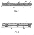
- a type of cross-section of the main back laths 7e, 7f and of the additional back lath 18 is illustrated which allows the attachment of a fire protection material 30, such as a gypsum layer, directly to the back surface 2 of the core panel 1.
- a fire protection material 30 such as a gypsum layer
- Fig. 7 illustrates a cross-section through an embodiment of the composite building element similar to that illustrated by Fig. 5.
- the front surface 12 of the core panel 1 is not provided with grooves or rabbets.
- the following example illustrates the composite building element of the present invention and its shear resistance compared to known building elements used in the industry.
- the core panel consists of rigid extruded polystyrene foam of a density of about 45 kg/m 3.
- the length of the panel is 240 cm, the width 120 cm and the thickness 80 mm.
- the stiff back frame is built of four main spruce laths of 75 mm x 5S mm cross-section and an additional spruce lath of 40 mm x 55 mm cross-section. In the corners, the main timber frame built by the spruce laths of 75 mm x 55 mm cross-section is reinforced by diagonally divided square steel nail plates of 300 mm side length and a thickness of 2 mm.
- the steel plates are nailed irregularly and glued with a polyurethane adhesive to the back frame and to the core panel.
- the stiff front frame is built of four main spruce laths and an additional spruce lath of 50 mm x 30 mm cross-section.
- the back and front timber frames are glued with a polyurethane adhesive to the back and front surfaces of the core panel.
- a spruce frame of 240 cm length and the same width is produced of
- the shear resistance of this frame is provided by a sheet of 8 mm plywood nailed with nails (2.1 x 45 mm) on each lath and stud of the frame, every 15 cm on the studs and the two outside laths and every 30 cm on the three middle 1 4 ths.
- a gypsum plaster board is nailed to the other side of the frame. The space between these two faces is filled with a glass fiber insulation of 100 mm thickness.
- the same frame as described in Comparative Example A is produced.
- the shear resistance is provided on both sides by a sheet of 12 mm chipboard nailed with nails (2.8 x 55, mm) every 15 cm on the studs and the two outside laths and every 30 cm on the three middle laths of the frame.
- the space between the two chipboard sheets is filled with a glass fiber insulation of 100 mm thickness.
Abstract
Description
- The present invention relates to composite building elements and in particular to composite building panels which have various applications in the building industry, for example for building walls, floors, ceilings and roofs.
- One popular method of building a wall is to build a timber frame which is then filled with glass wool. Since these timber frames are not highly shear resistant, a plywood sheathing is usually nailed to the timber frame. However, the plywood sheathing is relatively expensive and it does not always provide the building element with sufficient shear resistance. Insufficient shear resistance is also experienced when a chip board is nailed to the timber frame instead of plywood. The use of a chip board is furthermore disadvantageous because of the excessive weight of the chip board which is required to obtain satisfactory strength.
- In GB
patent specification 1 587 012 it is suggested to close a wall space defined by the timber frames of a building with a foamed polyurethane or a foamed polystyrene. However, such timber frames of which the wall space is filled with foamed polyurethane or polystyrene sheets have several disadvantages when building the walls. First, the size of the frame and of the foam sheet or slab must be very well adjusted to each other in order to avoid gaps between the frame and the foam sheet or slab. Special seals have been suggested in GBpatent specification 1 587 012 in order to fill such difficult to avoid gaps, but such seals increase the installation costs. Furthermore, the timber frame has much lower insulation properties than the foam sheet or slab and therefore forms thermal bridges in the building panel. - In DE-A-2816935 (equivalent to US-A-4193244) a module block is disclosed which consists of two parallel fiber plates. To each fiber plate two parallel laths are fixed. For connecting the two fiber plates with each other, side plates, for example fiber plates or chip boards, are fixed to the laths perpendicularly to the first two fiber plates.Between the four plates, an insulation material such as rock-wool is placed. However, fiber-plates, ply-wood or chip boards of heavy weight are required for providing sufficient shear strength to the module block. Furthermore, the side plates produced of fiber plates, chip board or ply-wood boards have insufficient insulation properties and therefore form thermal bridges in the module block.
- Therefore, it is desirable to provide a composite building element which does not only have good insulation properties but also high strength, in particular high shear resistance. It is also desirable to provide a building element which can be prefabricated and easily installed and which preferably has a relatively low weight.
- The present invention provides a composite building element which comprises
- a) a core panel of a rigid foamed material of an expanded synthetic resin and
- b) two stiff frames of essentially the same length and the same width as the length and width of the core panel which frames are bonded to the back and front surface of the core panel.
- The composite building element of the present invention has a surprisingly high resistance to shearing forces. Furthermore, the composite building element of the present invention does not provide thermal bridges.
-
- Fig. 1 illustrates a back perspective view on a first embodiment on the composite building element of the present invention.
- Fig. 2 illustrates a front perspective view on the first embodiment on the composite building element.
- Fig. 3 represents a schematic illustration of the cross-section of the composite building element along line A-A in Figs. 1 and 2.
- Fig. 4 to 7 are schematic illustrations of the cross-section of further embodiments of the composite building element of the invention.
- The composite building element of the present invention will be further described with reference to the drawings.
- With reference to Fig. 1, the composite building element comprises a
core panel 1 of a rigid foamed material of an expanded synthetic resin, such rigid foamed polyurethane or rigid foamed polystyrene. Preferably, thecore panel 1 is a rigid extruded polystyrene panel which has a density of from 20 kg/m3, preferably of from 30 kg/m3, to 60 kg/m3, preferably to 50 kg/m3. Most preferably, the core panel is moisture resistant. The thickness of thecore panel 1 depends on the desired insulating properties and strength of the building element. Preferably, the thickness is from 30 mm to 200 mm, most preferably from 50 mm to 120 mm. The length and width of the panel is not critical. Usual lengths are from 2 to 6 m, preferably from 2 to 3 m. Usual widths are from 0.6 to 12 m, preferably from 1 to 5. - A stiff back frame 3 and a stiff
front frame 5 are fixed to theback surface 2 and front surface of thecore panel 1. Theframes 3, 5 have essentially the same length and same width as the length and width of thecore panel 1, however, it is not necessary that the length and width of theframes 3, 5 are exactly the same as those of thecore panel 1. The back frame 3 consists of a first set of at least twoparallel laths 7a, 7b and a second set of at least twoparallel laths laths 7a, 7b. As illustrated by Fig. 1, the back frame 3 can be subdivided by one or moreadditional laths 8 which are preferably parallel to themain laths laths main laths additional lath 8 can have the same cross-section. In general, the cross-section of theadditional lath 8 is smaller, for example from 20 x 20 mm to 80 x 80 mm, preferably from 25 x 25 mm to 50 x 50 mm. Fig. 1 illustrates that the back frame 3 and thefront frame 5 are not in contact with each other. Therefore, the composite building element of the present invention does not provide the undesired thermal bridges through the thickness of the building element. The back frame 3 andfront frame 5 can be fixed to thecore panel 1 in any suitable means, preferably by applying an adhesive such as a polyurethane adhesive between the adjacent surfaces of the back frame 3 and thecore panel 1 and between the adjacent surfaces of thefront frame 5 and thecore panel 1. - The
main back laths additional back lath 8 can be fixed to each other by any suitable means to build the back frame 3 such as nailing or gluing If desired, the corners of the back frame 3 can be reinforced, for example by metal plates which are fixed to the corners of the back frame 3 and to thecore panel 1. - Fig. 2 illustrates the same embodiment of the composite building element of the present invention as Fig. 1, however, Fig. 2 represents a perspective front view on the building element. Fig. 2 illustrates a
core panel 1 as described with reference to Fig. 1. A stifffront frame 5 is fixed to thefront surface 12 of the core panel 1: Thefront frame 5 is built of a first set of at least twoparallel laths parallel laths laths main laths front laths 10. Thefront laths back laths front surface 12 of thecore panel 1 are rabbets (see 14a and 14b in Fig. 3) which have essentially the same widths and depths as the widths and thickness of themain front laths front surface 12 of thecore panel 1 is further provided with a groove (see 16 in Fig. 3) extending parallel to the edges of thecore panel 1 and which has essentially the same dimensions as the cross-section of the additionalfront lath 10. Thefront laths core panel 1. - As an alternative or in addition to the rabbets and groove(s) in the
front surface 12 of thecore panel 1, theback surface 2 of thecore'panel 1 can be provided with rabbets and/or one or more grooves. -
- Fig. 1 and 2 illustrate composite building elements of rectangular shape. In some cases however, it may be desirable that the core panel does not have a rectangular back or front surface but that is has surfaces of a triangular or trapezoid shape. Such shapes are for example preferred when building the portion of a wall which will be in contact with a sloped roof. In such a case, the two stiff frames are adjusted to the shape of the core panel. In one embodiment of the frames, each frame consists of one set of at least two parallel laths, a lath which is perpendicular to this set of parallel laths and one lath which is neither parallel nor perpendicular to this set of parallel laths.
- Fig. 3 illustrates a cross-section along the line A-A in Figs. 1 and 2. Fig. 3 illustrates how the
main back laths additional back lath 8 are arranged on theback surface 2 of thecore panel 1. Thefront surface 12 of thecore panel 1 is provided withrabbets groove 16. The main front laths 9c, 9d and the additionalfront lath 10 are placed in theserabbets groove 16 respectively and fixed to thecore panel 1. - Fig. 4 illustrates how the composite building panel described with reference to Fig. 3 can be combined with other materials to build a complete wall. An
interior finishing layer 20, for example a wood sheet or a gypsum plaster board is attached to the main back laths 7c, 7d and to theadditional lath 8 as well as to themain back laths 7a, 7b (not shown). Thereby aspace 22 is built which allows any pipes and electric cables to be fit into the building element in a convenient way. Thefront surface 12 of thecore panel 1 is covered with anexternal rendering 24. - Fig. 5 illustrates a cross-section through another embodiment of the composite building element of the present invention. The main front laths 9e, 9f, the main
front laths front lath 11 are not flush with thefront surface 12 of thecore panel 1 but are protruding. Anexternal finishing material 26 such as a wood cladding can be attached to the main front laths 9e, 9f, to the mainfront laths front lath 11 whereby asecond space 28 in addition tospace 22 is provided. - In Fig. 6 a type of cross-section of the
main back laths 7e, 7f and of theadditional back lath 18 is illustrated which allows the attachment of afire protection material 30, such as a gypsum layer, directly to theback surface 2 of thecore panel 1. - Fig. 7 illustrates a cross-section through an embodiment of the composite building element similar to that illustrated by Fig. 5. However, the
front surface 12 of thecore panel 1 is not provided with grooves or rabbets. - The following example illustrates the composite building element of the present invention and its shear resistance compared to known building elements used in the industry.
- A type of composite building element illustrated in Figs. 1 to 3 is tested. The core panel consists of rigid extruded polystyrene foam of a density of about 45 kg/m3. The length of the panel is 240 cm, the width 120 cm and the thickness 80 mm. The stiff back frame is built of four main spruce laths of 75 mm x 5S mm cross-section and an additional spruce lath of 40 mm x 55 mm cross-section. In the corners, the main timber frame built by the spruce laths of 75 mm x 55 mm cross-section is reinforced by diagonally divided square steel nail plates of 300 mm side length and a thickness of 2 mm. The steel plates are nailed irregularly and glued with a polyurethane adhesive to the back frame and to the core panel. The stiff front frame is built of four main spruce laths and an additional spruce lath of 50 mm x 30 mm cross-section. The back and front timber frames are glued with a polyurethane adhesive to the back and front surfaces of the core panel.
- A spruce frame of 240 cm length and the same width is produced of
- - 5 parallel laths of 240 cm length placed at equal distance from each other, the middle lath has a cross-section of 45 x 97 mm and the other four laths have a cross-section of 36 x 97 mm, and
- - a pair of studs of 36 x 97 mm cross-section which are perpendicular to the set of 5 parallel laths. Each stud is fixed to each lath with two nails of 3.3 x 90 mm.
- The shear resistance of this frame is provided by a sheet of 8 mm plywood nailed with nails (2.1 x 45 mm) on each lath and stud of the frame, every 15 cm on the studs and the two outside laths and every 30 cm on the three middle 14ths. A gypsum plaster board is nailed to the other side of the frame. The space between these two faces is filled with a glass fiber insulation of 100 mm thickness.
- The same frame as described in Comparative Example A is produced. The shear resistance is provided on both sides by a sheet of 12 mm chipboard nailed with nails (2.8 x 55, mm) every 15 cm on the studs and the two outside laths and every 30 cm on the three middle laths of the frame. The space between the two chipboard sheets is filled with a glass fiber insulation of 100 mm thickness.
- For testing the shear resistance of the building elements, two identical composite building panels of the Example are installed vertically side by side, fixed firmly to the floor and interconnected. One panel of each of Comparative Examples A and B is also installed vertically and fixed . firmly to the floor. Across the surface of the panels variable horizontal shearing forces are applied near the upper edge of the panels. The following table illustrates the weight of the building elements, the horizontal shearing force (load) which needs to be applied until the building element breaks, the horizontal shearing force (load) which is necessary to cause 5 mm deflection of the building element in the cases where a) no vertical load and b) additionally 2.5 kN vertical load is applied and the insulation properties of the building elements.
-


Claims (7)
Priority Applications (1)
| Application Number | Priority Date | Filing Date | Title |
|---|---|---|---|
| AT87111611T ATE50612T1 (en) | 1986-08-15 | 1987-08-11 | BUILDING COMPOSITE PANEL. |
Applications Claiming Priority (2)
| Application Number | Priority Date | Filing Date | Title |
|---|---|---|---|
| CH3290/86 | 1986-08-15 | ||
| CH3290/86A CH670671A5 (en) | 1986-08-15 | 1986-08-15 |
Publications (2)
| Publication Number | Publication Date |
|---|---|
| EP0260435A1 true EP0260435A1 (en) | 1988-03-23 |
| EP0260435B1 EP0260435B1 (en) | 1990-02-28 |
Family
ID=4252786
Family Applications (1)
| Application Number | Title | Priority Date | Filing Date |
|---|---|---|---|
| EP87111611A Expired - Lifetime EP0260435B1 (en) | 1986-08-15 | 1987-08-11 | Composite building panels |
Country Status (8)
| Country | Link |
|---|---|
| EP (1) | EP0260435B1 (en) |
| AT (1) | ATE50612T1 (en) |
| AU (1) | AU596683B2 (en) |
| CH (1) | CH670671A5 (en) |
| DE (1) | DE3761775D1 (en) |
| ES (1) | ES2013279B3 (en) |
| NO (1) | NO171647C (en) |
| NZ (1) | NZ221389A (en) |
Cited By (3)
| Publication number | Priority date | Publication date | Assignee | Title |
|---|---|---|---|---|
| WO2004059098A1 (en) * | 2002-12-30 | 2004-07-15 | Rozarijo Juric | Fast-construction wall panels |
| WO2011154539A1 (en) * | 2010-06-11 | 2011-12-15 | Module Home Future Bvba | Building system |
| JP2017057555A (en) * | 2015-09-14 | 2017-03-23 | 大建工業株式会社 | Panel and door with decorative joint |
Families Citing this family (7)
| Publication number | Priority date | Publication date | Assignee | Title |
|---|---|---|---|---|
| WO2002081841A1 (en) | 2001-04-03 | 2002-10-17 | James Hardie Research Pty Limited | Fiber cement siding planks, methods of making and installing |
| US8297018B2 (en) | 2002-07-16 | 2012-10-30 | James Hardie Technology Limited | Packaging prefinished fiber cement products |
| US8281535B2 (en) | 2002-07-16 | 2012-10-09 | James Hardie Technology Limited | Packaging prefinished fiber cement articles |
| US7993570B2 (en) | 2002-10-07 | 2011-08-09 | James Hardie Technology Limited | Durable medium-density fibre cement composite |
| US7998571B2 (en) | 2004-07-09 | 2011-08-16 | James Hardie Technology Limited | Composite cement article incorporating a powder coating and methods of making same |
| MX2008013202A (en) | 2006-04-12 | 2009-01-09 | James Hardie Int Finance Bv | A surface sealed reinforced building element. |
| DE102014112987A1 (en) * | 2014-09-09 | 2016-03-10 | Holz Element Produktion Gmbh & Co. Kg | module element |
Citations (1)
| Publication number | Priority date | Publication date | Assignee | Title |
|---|---|---|---|---|
| DE2816935A1 (en) * | 1977-04-19 | 1978-11-02 | Sture Lennart Samuelsson | MODULAR BLOCK AND SYSTEM FOR HOUSE CONSTRUCTION |
Family Cites Families (3)
| Publication number | Priority date | Publication date | Assignee | Title |
|---|---|---|---|---|
| US3305986A (en) * | 1962-08-07 | 1967-02-28 | Foam Products Corp | Insulated enclosures and panels therefor |
| CA1124482A (en) * | 1978-06-28 | 1982-06-01 | Cano Thermo Systems Inc. | Panel structure and building structures made therefrom |
| DE3440297A1 (en) * | 1984-11-05 | 1986-05-22 | Greschbach, Manfred, 7637 Ettenheim | PANEL SHAPED WALL ELEMENT |
-
1986
- 1986-08-15 CH CH3290/86A patent/CH670671A5/de not_active IP Right Cessation
-
1987
- 1987-08-10 AU AU76734/87A patent/AU596683B2/en not_active Ceased
- 1987-08-10 NZ NZ221389A patent/NZ221389A/en unknown
- 1987-08-11 ES ES87111611T patent/ES2013279B3/en not_active Expired - Lifetime
- 1987-08-11 EP EP87111611A patent/EP0260435B1/en not_active Expired - Lifetime
- 1987-08-11 DE DE8787111611T patent/DE3761775D1/en not_active Expired - Fee Related
- 1987-08-11 AT AT87111611T patent/ATE50612T1/en not_active IP Right Cessation
- 1987-08-14 NO NO873431A patent/NO171647C/en not_active IP Right Cessation
Patent Citations (1)
| Publication number | Priority date | Publication date | Assignee | Title |
|---|---|---|---|---|
| DE2816935A1 (en) * | 1977-04-19 | 1978-11-02 | Sture Lennart Samuelsson | MODULAR BLOCK AND SYSTEM FOR HOUSE CONSTRUCTION |
Cited By (4)
| Publication number | Priority date | Publication date | Assignee | Title |
|---|---|---|---|---|
| WO2004059098A1 (en) * | 2002-12-30 | 2004-07-15 | Rozarijo Juric | Fast-construction wall panels |
| HRP20021035B1 (en) * | 2002-12-30 | 2011-02-28 | Jurić Rozarijo | Wall panels for fast construction of structures |
| WO2011154539A1 (en) * | 2010-06-11 | 2011-12-15 | Module Home Future Bvba | Building system |
| JP2017057555A (en) * | 2015-09-14 | 2017-03-23 | 大建工業株式会社 | Panel and door with decorative joint |
Also Published As
| Publication number | Publication date |
|---|---|
| ATE50612T1 (en) | 1990-03-15 |
| EP0260435B1 (en) | 1990-02-28 |
| NO171647B (en) | 1993-01-04 |
| NO873431D0 (en) | 1987-08-14 |
| AU596683B2 (en) | 1990-05-10 |
| CH670671A5 (en) | 1989-06-30 |
| NO873431L (en) | 1988-02-16 |
| AU7673487A (en) | 1988-02-18 |
| DE3761775D1 (en) | 1990-04-05 |
| NO171647C (en) | 1993-04-14 |
| ES2013279B3 (en) | 1990-05-01 |
| NZ221389A (en) | 1991-12-23 |
Similar Documents
| Publication | Publication Date | Title |
|---|---|---|
| US6205729B1 (en) | Asymmetric structural insulated panel | |
| US10024057B2 (en) | Construction panel system and methods of assembly thereof | |
| US5899037A (en) | Composite wall structure | |
| US6209284B1 (en) | Asymmetric structural insulated panels for use in 2X stick construction | |
| US5685124A (en) | Wall, ceiling or roof elements with heat insulation properties on one side and sound insulation properties on the other | |
| US4603531A (en) | Structural panels | |
| US5483778A (en) | Modular panel system having a releasable tongue member | |
| US4304080A (en) | Construction beam | |
| EP0536161A1 (en) | Floor construction. | |
| EP0260435B1 (en) | Composite building panels | |
| WO1994013897A1 (en) | Foam sandwich enclosure with interlocking integral frame | |
| US5617700A (en) | Prefabricated building panel | |
| US6032434A (en) | Half-timber frame and half-timber compartment element | |
| US6330775B1 (en) | Prefabricated building wall structure | |
| DE4413953A1 (en) | Wall, ceiling or roof element for panel-type buildings | |
| US20040226255A1 (en) | Composite beam | |
| FI98398C (en) | Wall element | |
| US20050102962A1 (en) | Timber block | |
| KR20130055945A (en) | The insulation complex panel with structural wood and the construct method of wall therewith | |
| JP2022520979A (en) | Building studs, wall structures with such building studs, and methods for forming wall structures. | |
| JPH11131683A (en) | Composite panel | |
| US4490955A (en) | Residential wall construction | |
| JP2561588B2 (en) | Construction method of partition in building | |
| JP2000170305A (en) | Sound insulation floor panel and sound insulation floor panel mounting structure | |
| TW218905B (en) |
Legal Events
| Date | Code | Title | Description |
|---|---|---|---|
| PUAI | Public reference made under article 153(3) epc to a published international application that has entered the european phase |
Free format text: ORIGINAL CODE: 0009012 |
|
| AK | Designated contracting states |
Kind code of ref document: A1 Designated state(s): AT BE CH DE ES FR GB IT LI NL SE |
|
| 17P | Request for examination filed |
Effective date: 19880603 |
|
| 17Q | First examination report despatched |
Effective date: 19890605 |
|
| GRAA | (expected) grant |
Free format text: ORIGINAL CODE: 0009210 |
|
| RAP1 | Party data changed (applicant data changed or rights of an application transferred) |
Owner name: THE DOW CHEMICAL COMPANY |
|
| AK | Designated contracting states |
Kind code of ref document: B1 Designated state(s): AT BE CH DE ES FR GB IT LI NL SE |
|
| PG25 | Lapsed in a contracting state [announced via postgrant information from national office to epo] |
Ref country code: LI Effective date: 19900228 Ref country code: CH Effective date: 19900228 |
|
| REF | Corresponds to: |
Ref document number: 50612 Country of ref document: AT Date of ref document: 19900315 Kind code of ref document: T |
|
| ET | Fr: translation filed | ||
| REF | Corresponds to: |
Ref document number: 3761775 Country of ref document: DE Date of ref document: 19900405 |
|
| ITF | It: translation for a ep patent filed |
Owner name: ING. A. GIAMBROCONO & C. S.R.L. |
|
| REG | Reference to a national code |
Ref country code: CH Ref legal event code: PL |
|
| PLBE | No opposition filed within time limit |
Free format text: ORIGINAL CODE: 0009261 |
|
| STAA | Information on the status of an ep patent application or granted ep patent |
Free format text: STATUS: NO OPPOSITION FILED WITHIN TIME LIMIT |
|
| 26N | No opposition filed | ||
| ITTA | It: last paid annual fee | ||
| EAL | Se: european patent in force in sweden |
Ref document number: 87111611.7 |
|
| PGFP | Annual fee paid to national office [announced via postgrant information from national office to epo] |
Ref country code: SE Payment date: 20000619 Year of fee payment: 14 Ref country code: GB Payment date: 20000619 Year of fee payment: 14 |
|
| PGFP | Annual fee paid to national office [announced via postgrant information from national office to epo] |
Ref country code: FR Payment date: 20000627 Year of fee payment: 14 |
|
| PGFP | Annual fee paid to national office [announced via postgrant information from national office to epo] |
Ref country code: NL Payment date: 20000630 Year of fee payment: 14 |
|
| PGFP | Annual fee paid to national office [announced via postgrant information from national office to epo] |
Ref country code: AT Payment date: 20000717 Year of fee payment: 14 |
|
| PGFP | Annual fee paid to national office [announced via postgrant information from national office to epo] |
Ref country code: DE Payment date: 20000718 Year of fee payment: 14 |
|
| PGFP | Annual fee paid to national office [announced via postgrant information from national office to epo] |
Ref country code: ES Payment date: 20000808 Year of fee payment: 14 |
|
| PGFP | Annual fee paid to national office [announced via postgrant information from national office to epo] |
Ref country code: BE Payment date: 20000818 Year of fee payment: 14 |
|
| PG25 | Lapsed in a contracting state [announced via postgrant information from national office to epo] |
Ref country code: GB Free format text: LAPSE BECAUSE OF NON-PAYMENT OF DUE FEES Effective date: 20010811 Ref country code: AT Free format text: LAPSE BECAUSE OF NON-PAYMENT OF DUE FEES Effective date: 20010811 |
|
| PG25 | Lapsed in a contracting state [announced via postgrant information from national office to epo] |
Ref country code: SE Free format text: LAPSE BECAUSE OF NON-PAYMENT OF DUE FEES Effective date: 20010812 Ref country code: ES Free format text: LAPSE BECAUSE OF NON-PAYMENT OF DUE FEES Effective date: 20010812 |
|
| PG25 | Lapsed in a contracting state [announced via postgrant information from national office to epo] |
Ref country code: BE Free format text: LAPSE BECAUSE OF NON-PAYMENT OF DUE FEES Effective date: 20010831 |
|
| BERE | Be: lapsed |
Owner name: THE DOW CHEMICAL CY Effective date: 20010831 |
|
| PG25 | Lapsed in a contracting state [announced via postgrant information from national office to epo] |
Ref country code: NL Free format text: LAPSE BECAUSE OF NON-PAYMENT OF DUE FEES Effective date: 20020301 |
|
| EUG | Se: european patent has lapsed |
Ref document number: 87111611.7 |
|
| GBPC | Gb: european patent ceased through non-payment of renewal fee |
Effective date: 20010811 |
|
| PG25 | Lapsed in a contracting state [announced via postgrant information from national office to epo] |
Ref country code: FR Free format text: LAPSE BECAUSE OF NON-PAYMENT OF DUE FEES Effective date: 20020430 |
|
| NLV4 | Nl: lapsed or anulled due to non-payment of the annual fee |
Effective date: 20020301 |
|
| PG25 | Lapsed in a contracting state [announced via postgrant information from national office to epo] |
Ref country code: DE Free format text: LAPSE BECAUSE OF NON-PAYMENT OF DUE FEES Effective date: 20020501 |
|
| REG | Reference to a national code |
Ref country code: FR Ref legal event code: ST |
|
| REG | Reference to a national code |
Ref country code: ES Ref legal event code: FD2A Effective date: 20020911 |
|
| PG25 | Lapsed in a contracting state [announced via postgrant information from national office to epo] |
Ref country code: IT Free format text: LAPSE BECAUSE OF NON-PAYMENT OF DUE FEES;WARNING: LAPSES OF ITALIAN PATENTS WITH EFFECTIVE DATE BEFORE 2007 MAY HAVE OCCURRED AT ANY TIME BEFORE 2007. THE CORRECT EFFECTIVE DATE MAY BE DIFFERENT FROM THE ONE RECORDED. Effective date: 20050811 |